EP1585231B1 - Verfahren zur kalibrierung intelligenter antennengruppensysteme in echtzeit - Google Patents
Verfahren zur kalibrierung intelligenter antennengruppensysteme in echtzeit Download PDFInfo
- Publication number
- EP1585231B1 EP1585231B1 EP03782075A EP03782075A EP1585231B1 EP 1585231 B1 EP1585231 B1 EP 1585231B1 EP 03782075 A EP03782075 A EP 03782075A EP 03782075 A EP03782075 A EP 03782075A EP 1585231 B1 EP1585231 B1 EP 1585231B1
- Authority
- EP
- European Patent Office
- Prior art keywords
- calibration
- link
- sequence
- receiving
- transmitting
- Prior art date
- Legal status (The legal status is an assumption and is not a legal conclusion. Google has not performed a legal analysis and makes no representation as to the accuracy of the status listed.)
- Expired - Lifetime
Links
- 238000000034 method Methods 0.000 title claims abstract description 43
- 230000004044 response Effects 0.000 claims abstract description 41
- 230000001351 cycling effect Effects 0.000 claims abstract description 7
- 230000000737 periodic effect Effects 0.000 claims abstract description 7
- 239000013598 vector Substances 0.000 claims description 47
- 238000010295 mobile communication Methods 0.000 claims description 5
- 230000008569 process Effects 0.000 claims description 4
- 238000009434 installation Methods 0.000 abstract description 2
- 238000004891 communication Methods 0.000 description 8
- 238000005516 engineering process Methods 0.000 description 6
- 238000012423 maintenance Methods 0.000 description 4
- 238000003491 array Methods 0.000 description 3
- 230000005540 biological transmission Effects 0.000 description 2
- 230000008878 coupling Effects 0.000 description 2
- 238000010168 coupling process Methods 0.000 description 2
- 238000005859 coupling reaction Methods 0.000 description 2
- 238000013461 design Methods 0.000 description 2
- 238000010586 diagram Methods 0.000 description 2
- 238000012545 processing Methods 0.000 description 2
- 230000035945 sensitivity Effects 0.000 description 2
- 230000008859 change Effects 0.000 description 1
- 230000003247 decreasing effect Effects 0.000 description 1
- 230000007613 environmental effect Effects 0.000 description 1
- 238000007726 management method Methods 0.000 description 1
- 238000004519 manufacturing process Methods 0.000 description 1
- 238000005259 measurement Methods 0.000 description 1
- 238000012986 modification Methods 0.000 description 1
- 230000004048 modification Effects 0.000 description 1
- 230000001681 protective effect Effects 0.000 description 1
- 230000001360 synchronised effect Effects 0.000 description 1
- 238000012360 testing method Methods 0.000 description 1
Images

Classifications
-
- H—ELECTRICITY
- H04—ELECTRIC COMMUNICATION TECHNIQUE
- H04W—WIRELESS COMMUNICATION NETWORKS
- H04W16/00—Network planning, e.g. coverage or traffic planning tools; Network deployment, e.g. resource partitioning or cells structures
- H04W16/24—Cell structures
- H04W16/28—Cell structures using beam steering
-
- H—ELECTRICITY
- H01—ELECTRIC ELEMENTS
- H01Q—ANTENNAS, i.e. RADIO AERIALS
- H01Q3/00—Arrangements for changing or varying the orientation or the shape of the directional pattern of the waves radiated from an antenna or antenna system
- H01Q3/26—Arrangements for changing or varying the orientation or the shape of the directional pattern of the waves radiated from an antenna or antenna system varying the relative phase or relative amplitude of energisation between two or more active radiating elements; varying the distribution of energy across a radiating aperture
- H01Q3/267—Phased-array testing or checking devices
-
- H—ELECTRICITY
- H04—ELECTRIC COMMUNICATION TECHNIQUE
- H04B—TRANSMISSION
- H04B7/00—Radio transmission systems, i.e. using radiation field
- H04B7/02—Diversity systems; Multi-antenna system, i.e. transmission or reception using multiple antennas
Definitions
- the present invention generally relates to a smart antenna technology of the wireless communication system, more specifically, to a method for calibrating a smart antenna array system in real time.
- the base station comprises an antenna array with one or more than one antenna elements, radio frequency (RF) cables and RF transceivers correspondingly connected.
- RF radio frequency
- a baseband signal processor Based on the signals received from the user terminal in each antenna element of the antenna array, a baseband signal processor can obtain the space vector characteristics and direction of arrival (DOA) of the uplink signals, from which the weights of every link obtained are employed for downlink transmitting beam forming. In this way, all the functionality of a smart antenna is achieved under the circumstances of symmetrical radio wave propagation characterized as the result of time-division duplex communication.
- the procedure and method for amplitude and phase compensation of each transmitting and receiving link are the smart antenna calibration relating to the present invention.
- the sensitivities thereof to operation frequency and ambient temperature are different, and the changes in the characteristics of every transmitting and receiving link due to the reasons above are different, the smart antenna calibration should be carried out periodically while the base station is in operation.
- a calibrating link is set by an antenna element 201, a couple structure 205, a RF cable 206 and a pilot transceiver 207 sequentially connected.
- the couple structure 205 sets up a RF couple connection with all the antenna elements 201-1, 201-2 ... 201-N of the smart antenna, and allocates the RF signals to all antenna elements constituting the array according to need.
- the pilot transceiver 207 has the same structure as the other transceivers 203-1, 203-2...203-N of the base station and uses a common local oscillator 208.
- the pilot transceiver 207 works coherently with other transceivers and connects with the baseband signal processor 204 via a digital bus.
- Each antenna element connects to a RF cable and further to a transceiver, and the connected antenna element, RF cable and transceiver form a transmitting link or a receiving link.
- Ac, A 1 , A 2 ,...A N in Fig. 1 represent the connection points between the antenna elements and the RF cables 201-1, 201-2 ... 201-N, respectively;
- B C , B 1 , B 2 ...B N represent the connection points of the pilot transceiver 207 and the radio transceivers 203-1, 203-2...203-N with the baseband signal processor 204, respectively.
- calibrate the calibration link first by using a network vector analyzer and record the receiving and transmitting transmission coefficients of the calibration link respectively, then perform the receiving calibration and transmitting calibration respectively.
- the pilot transceiver transmits a signal at a given working frequency, and all the other links in the base station are set in the receiving state. Measure the outputs of all the receiving links and compute the ratio of the receiving transmission-coefficient (vector) of each link to the transmission-coefficient (vector) of a reference link. When the ratio of the amplitudes of the transmission-coefficients equals to 1, record the phase difference of each receiving link from the reference link.
- EP 1 204 161 is a family member
- the patent mentioned above only relates to the general scheme of the method and apparatus for real-time calibration without a specific engineering implementation thereof, including the calibration sequence used in the transmitting and receiving calibration and the computation by the baseband signal processor, and how to perform the real-time calibration when the smart antenna is in operation.
- the transmitting calibration as described above is carried out with one link in the transmitting state at a time while all other links are in the receiving state, which is unfavorable for fast real-time calibration.
- EP 0 805 510 discloses a method of self calibration of an active array system, a module under test being phase-modulated using a special command to increment the phase from pulse to pulse.
- the technical solution to achieve the above object is as follows: pre-calibrating each antenna element of a smart antenna array (201-1 to 201-N) to obtain the transmitting compensation coefficient c k TX and the receiving compensation coefficient C k RX of each antenna element (201-1 to 201-N) relative to a calibration antenna element (201), characterized in that:
- the pre-calibrating is carried out after the production of the smart antenna array.
- the transmitting and receiving compensation coefficients obtained will be stored.
- the stored pre-calibration transmitting and receiving compensation coefficients obtained in the pre-calibrating are inputted into the baseband signal processor of the base station.
- Generating a calibration signal by a periodic cycling shift of a basic calibration sequence includes: taking a binary sequence m p as the basic calibration sequence with a length P; performing a phase equalization to the sequence m p to generate m p , a complex vector for the calibration sequence; expanding the m p periodically to obtain a new periodical complex vector; obtaining a calibration vector for each antenna element from the m; generating a calibration signal for each antenna element from the calibration vector for each antenna element.
- the length of said basic calibration sequence is W ⁇ N and the length of said calibration sequence is W ⁇ N+W-1, where N is the number of antenna elements in the antenna array, and W is the window length in channel estimation for each transmitting or receiving link.
- Said transmitting calibration and receiving calibration are periodically performed in the idle gap of the mobile communication system.
- said transmitting calibration and receiving calibration are performed in the protective gap (GP) between the uplink pilot time-slot and the downlink pilot time-slot in a frame.
- Said computing the compensation coefficient of each transmitting link in the transmitting calibration comprises: first, obtaining the channel impulse response of each transmitting link; second, computing the amplitude and phase response of the path between each transmitting link, including the transceiver, and the calibration link antenna element; third, multiplying the amplitude and phase response with the transmitting compensation coefficient of the corresponding link obtained in pre-calibrating, and then obtaining the transmitting compensation coefficient of each link.
- Said computing the compensation coefficient of each receiving link in the receiving calibration comprises: first, obtaining the channel impulse response of each receiving link; second, computing the amplitude and phase response of the path between each receiving link, including the calibration link antenna element, and the transceiver; third, multiplying the amplitude and phase response with the receiving compensation coefficient of the corresponding link obtained in the pre-calibrating, and then obtain the receiving compensation coefficient of each link.
- the real-time calibration method of this invention for which it is necessary to set a calibration link specially for realizing the calibration function (as described in the background of the invention) which consists of an antenna element, a feeder cable and a pilot transceiver: before the delivery of the antenna array, first pre-calibrating the antenna array to obtain compensation coefficients of each antenna element relative to a calibration antenna element; then storing the compensation coefficients in the network operation and maintenance equipment; after the on-site installation of the smart antenna array, loading the compensation coefficient into the base station.
- Said calibration performed periodically while the base station is in operation further comprises: in the transmitting calibration, the transmitting links simultaneously transmitting a fixed level calibration sequence, which is received by the calibration link as a combined signal thereof; in the receiving calibration, the calibration link transmitting a fixed level calibration sequence, which is received simultaneously by the receiving links.
- the compensation coefficients of the transmitting and receiving links of the smart antenna array can be obtained so that the real-time calibration can be accomplished.
- the fixed level calibration sequence employed is generated by a periodic cycling shift to a basic calibration sequence.
- the method of the present invention has the advantages of short computation time and simple controls. It is especially suitable for a smart antenna array in the third generation mobile communication system with high chip rate.
- the method of the present invention is fully applicable, after simple modification, to frequency division multiple access and time division multiple access wireless communication systems. It can not only be used to calibrate a smart antenna operating in TDD mode, but also a smart antenna operating in FDD mode.
- the method of the present invention is proposed on the basis of an antenna array which is a passive microwave (radio frequency) network. Characteristics of mutual coupling between each antenna element of this antenna array and the calibration antenna element remain unchanged at a given working frequency provided that the design of the antenna array product has been finalized and the structure thereof is fixed. Therefore, before delivery of the antenna array, each antenna element of the antenna array can be tested relative to the calibration antenna element at a given working frequency or can be pre-calibrated to obtain the compensation coefficient of each antenna element relative to the calibration antenna element which is then stored in the network management database as the pre-calibration data. After the antenna array has been installed on site, the antenna array pre-calibration data are loaded to the base station by the network operation and maintenance equipment, such as OMC_R or LMT. In this way, the antenna array can be calibrated with the real-time calibration method according to the present invention when the antenna array starts into operation.
- the network operation and maintenance equipment such as OMC_R or LMT.
- the method of the invention can be employed in a typical time-division duplex (TDD) CDMA base station equipped with a smart antenna.
- TDD time-division duplex
- the configuration of the base station is shown in Fig. 1 .
- the base station comprises N identical antenna elements 201-1, 201-2 ... 201-N; N identical feeder cables 202-1, 202-2 ... 202-N; N RF transceivers 203-1, 203-2 ... 203-N that work coherently; and an appropriate baseband signal processor 204.
- a calibration (reference) link which consists of a RF coupling structure 205, a calibration antenna element 201, a feeder cable 206 and a pilot transceiver 207, wherein the pilot transceiver 207 works coherently with N transceivers 203-1, 203-2 ... 203-N, and uses a common local oscillator 208.
- N transceivers 203-1, 203-2 ... 203-N and the pilot transceiver 207 connect with the baseband signal processor 204 via a data bus.
- the real-time calibration method of the present invention comprises the following key steps:
- the radio frequency network vector analyzer 21 performs the transmitting and receiving pre-calibration respectively.
- the structure of the smart antenna is rather firm by design, it can be recognized that the channel characteristics between each antenna element 201-1, 201-2 ... 201-N and the calibration antenna unit 201 remain unchanged on the whole with the environmental conditions at a fixed working frequency, given that there is no disruption of the relative location. So it is possible to perform the pre-calibration measurement using a radio frequency network vector analyzer.
- the antenna element of the calibration link 201 transmits a fixed level digital signal, which is received by each antenna element 201-1, 201-2 ...
- each transceiver is connected to the same antenna element (i.e. the transmitting and receiving links have a common antenna element)
- the second step inputting the above pre-calibration result (the transmitting compensation coefficient and the receiving compensation coefficient) in the network operation and maintenance equipment.
- the antenna array compensation coefficients are loaded to the baseband signal processor of the base station to which the antenna array is connected by the network operation and maintenance equipment, such as OMC_R or LMT.
- the third step is carried out while the base station starts operation or is in operation.
- This step comprises: generating a calibration sequence; performing the transmitting calibration; performing the receiving calibration; and computing the transmitting and receiving compensation coefficients.
- the calibration sequence is generated by a periodic cycling shift of a basic calibration sequence selected with good anti-white-noise characteristics.
- the length of the basic calibration sequence P is W ⁇ N, where N is the number of operating antenna elements of the antenna array, and W is the window length in the channel estimation of each link.
- the length of the calibration sequence when performing the transmitting and receiving calibration is W ⁇ N + W - 1, that is, P + W - 1.
- N can take a larger value in order to have a larger antenna gain for the system.
- a vector S relating to the basic calibration sequence should be computed for this invention as well, which is stored in the baseband signal processor as a constant vector for computing the compensation coefficients when performing the transmitting and receiving calibrations:
- fft represents the Fast Fourier Transform Algorithm.
- the selecting the basic calibration sequence step refers to selecting a binary sequence which makes S have a minimum norm and has a length P.
- the transmitting calibration comprises the following steps: each antenna element transmitting a fixed level calibration sequence simultaneously, and the calibration link receiving the combined signal thereof.
- the baseband signal processor processing the signal data received by the calibration link, computing the amplitude and phase response of each transmitting link, and then computing the compensation coefficient (including the amplitude and the phase compensation) for each transmitting link according to the compensation coefficient (transmitting compensation coefficient) thereof obtained during pre-calibration, by which all the downlink data of the base station are compensated at the baseband signal processor.
- the baseband signal processor computes the received data from the calibration link (201, 206 and 207) to obtain the amplitude and phase response of each transmitting link B k ⁇ A k ⁇
- the amplitude and phase response of the link B k ⁇ A k ⁇ A C ⁇ B C is needed. Since the amplitude and phase response of the path A k ⁇ A C has been obtained in the pre-calibration, only the amplitude and phase response of the path B k ⁇ A k needs to be computed.
- R p ( r 1 , r 2 ,..., r p ).
- R p ( r 1 , r 2 ,..., r p ).
- the transmitting compensation coefficient of the k th link can be obtained.
- the receiving calibration comprises the following steps: the calibration link transmitting a fixed level calibration sequence signal, which is received by each receiving link simultaneously.
- the baseband signal processor computing the amplitude and phase response of each receiving link on the basis of the received data at each receiving link, by which and the receiving compensation coefficient obtained in the pre-calibration the compensation coefficient (including the amplitude and phase compensation) of each receiving link is computed and obtained. With the compensation coefficients, all downlink data of the base station can be compensated in the baseband signal processor.
- the signal is received by each receiving link through the couple structure 205, each antenna element of the antenna array 201-1 ... 201-N each feeder cable 202-1, ...202-N, each transceiver 203-1, ...203-N.
- the baseband signal processor 204 computes the data received from each receiving link to obtain the amplitude and phase response of each receiving link ( A k ⁇ B k ).
- the amplitude and phase response of the path B c ⁇ A c ⁇ A k ⁇ B k is needed, since the amplitude and phase response of the path A c ⁇ A k have been obtained in pre-calibration, only the amplitude and phase response of the path A k ⁇ B k needs to be computed.
- R ⁇ P k r ⁇ 1 k r ⁇ 2 k ... r ⁇ p k .
- f max is an interpolation function to evaluate the peak between the channel estimation results c 1 k ⁇ c w ⁇ k k of the k th receiving link (the specific value depends on the required computation accuracy)
- CIR k is a complex number containing the amplitude and phase response of the path B k ⁇ A c of the k th link.
- the calibration method is independent of the transmitting calibration and the receiving calibration, so the method of the present invention can also be implemented in an FDD CDMA base station which uses different smart antenna arrays to transmit and receive signals.
- data transmitted and received are compensated respectively by the baseband signal processor using the transmitting compensation coefficient and the receiving compensation coefficient computed.
- TD-SCDMA Time-Slot
- DwPTS Downlink Pilot Time-Slot
- the calibration by this method can be periodically performed while the base station is in operation.
Landscapes
- Engineering & Computer Science (AREA)
- Computer Networks & Wireless Communication (AREA)
- Signal Processing (AREA)
- Radio Transmission System (AREA)
- Variable-Direction Aerials And Aerial Arrays (AREA)
- Mobile Radio Communication Systems (AREA)
- Radar Systems Or Details Thereof (AREA)
Claims (11)
- Verfahren zum Kalibrieren von intelligenten Antennengruppensystemen in Echtzeit, umfassend: Vorkalibrieren eines jeden Antennenelements einer intelligenten Antennengruppe (201-1 bis 201-N), um den Übertragungskompensationskoeffizienten

 in einem Übertragungskalibrierprozess eine Vielzahl von Übertragungsstrecken jedes Kalibriersignal gleichzeitig übertragen und eine Kalibrierstrecke ein kombiniertes Signal davon empfängt, wobei ein Basisband-Signalprozessor (204) das von der Kalibrierstrecke empfangene kombinierte Signal verarbeitet, um den Amplituden- und Phasengang einer jeden Übertragungsstrecke zu erhalten, und den Kompensationskoeffizienten einer jeden Übertragungsstrecke berechnet auf der Basis des Amplituden- und Phasengangs einer jeden Übertragungsstrecke und der Übertragungskompensationskoeffizienten
 in einem Empfangskalibrierprozess die Kalibrierstrecke ein Kalibriersignal überträgt, und die Empfangsstrecken das Kalibriersignal gleichzeitig empfangen, dann der Basisband-Signalprozessor (204) die von den Empfangsstrecken empfangenen Kalibriersingale verarbeitet, um den Amplituden- und Phasengang einer jeden Empfangsstrecke zu erhalten, dann den Kompensationskoeffizienten einer jeden Empfangsstrecke berechnet auf der Basis des Amplituden- und Phasengangs einer jeden Empfangsstrecke und der Empfangskorrpensationskoeffizienten
 das Kalibriersignal für jedes Antennenelement durch eine periodische zyklische Verschiebung einer Basiskalibrierfolge erzeugt wird und das Kalibriersignal eine Kalibrierfolge mit guten Anti-Weißrauschen-Charakteristiken ist.
 - Verfahren nach Anspruch 1, worin das Erzeugen eines Kalibriersignals durch eine periodische zyklische Verschiebung einer Basiskalibrierfolge Folgendes umfasst:Setzen einer Binärfolge mP der Länge P als die Basiskalibrierfolge, m P = (m 1,m 2,...,m P), wo P = w×N, N die Anzahl der Antennenelemente der intelligenten Antennengruppe ist und w die Fensterlänge der Kanalschätzung einer jeden Übertragungs- oder Empfangsstrecke ist;Ausführen einer Phasenentzerrung an der Folge mP, Erzeugen eines komplexen Vektors der Kalibrierfolge m P, m P = ( m 1, m 2,..., m P ), wo das Element der Folge m i = (j)i-1. m i ist mit i = 1,...,P, und j die Quadratwurzel von -1 ist;periodische Entwicklung von m P und Erhalten eines neuen periodischen komplexen Vektors m, m = ( m 1, m 2,···, m t
max ) = ( m 2, m 3,..., m P , m 1, m 2,..., m P );Erhalten eines Kalibrierfolgevektors mit einer Länge Lm=P+w-1 für jedes Antennenelement aus dem periodischen komplexen Vektor m,
 Erzeugen einer Kalibrierfolge des Signals mit einer festen Leistung vom Kalibrierfolgevektor auf der Basis der Kalibrierauforderung.
 - Verfahren nach Anspruch 2, worin P als eine Potenz von 2 gewählt wird.
- Verfahren nach Anspruch 1, worin die Übertragungsklibrierung und Empfangskalibrierung periodisch in der Untätigkeitslücke eines Mobilkommunikationssystems ausgeführt werden.
- Verfahren nach Anspruch 1, worin in einem TD-SCDMA-System die Übertragungskalibrierung und Empfangskalibrierung periodisch in der Schutzlücke zwischen Aufwärtsstrecken-Pilotzeitschlitz und Abwärtsstrecken-Pitotzeitschlitz in einem Rahmen ansgeführt werden.
- Verfahren nach Anspruch 1, worin das Berechnen des Kompensationskoeffizienten einer jeden Übertragungsstrecke in der Übertragungskalibrierung Folgendes umfasst:Erhalten des komplexen Vektors des kombinierten Signals, das von der Kalibrierstrecke empfangen wird: R = (r1,r2,....,rl ), wo l = P+2×(w-1), P = w×N die Länge der Basiskalibrierfolge darstellt, N die Anzahl der Antennenelemente der intelligenten Antennengruppe ist und w die Fensterlänge in der Kanalschätzung einer jeden Übertragungsstrecke ist;Eliminieren aus dem Vektor von einem Abschnitt R P = (r 1, r 2,...,rP) mit einer Länge gleich der Länge P der Basiskalibrierfolge;Berechnen einer Kanalimpulsgaugfolge mit einer Länge P unter Verwendung der Formel

wo S ein konstanter Vektor ist; Berechnen einer Kanalimpulsgangfolge mit einer Länge P unter Verwendung der Formel
wo k = 1,...,N, und S ein konstanter Vektor ist;Berechnen einer Interpolationsfunktion des Spitzenwerts zwischen den Kanaischätzungsergebnissen c wx(k-1)+1 ∼ c wxk der k-ten Übertragungsstrecke:
und Erhalten des Amplituden- und Phasengangs der k-ten Strecke einschließlich des Pfads zwischen dem Sender (203-k) und dem Antennenelement der Kalibrierstrecke (201), k = 1,...,N;Multiplizieren von CIRk mit dem ÜbertragungskompensationskoeffizientenBerechnen der mittleren Leistung einer Übertragungsstrecke mit der folgenden Formel:


Berechnen des Übertragungskompensationskoeffizienten einer jeden Übertragungsstrecke mit der folgenden Formel:
- Verfahren nach Anspruch 6, worin das Eliminieren aus dem Vektor von einem Abschnitt R P = (r 1, r 2,..., r p) mit einer Länge gleich der Länge P der Basiskalibrierfolge durch Eliminieren eines Teils der Folge ausgeführt wird, wie durch die folgende Formel ausgedrückt ist: R p = (r w-1,rw , ..., r w+p-2).
- Verfahren nach Anspruch 6, worin der konstante Vektor S durch die Formel

berechnet wird, wo der komplexe Vektor der Kalibrierfolge m P = ( m 1, m 2,..., m p ) durch eine Phasenentzerrung an der Basiskalibrierfolge m P (m 1,m 2,...,mp ) erzeugt wird, wo das Element der Folge m i = (j)i-1 · mi ist mit i = 1,...,P, P ≃ w×N die Länge der Basiskalibrierfolge darstellt, N die Anzahl der Antennenelemente der intelligenten Antennengruppe ist und w die Fensterlänge in der Kanalschätzung einer jeden Übertragungsstrecke ist. - Verfahren nach Anspruch 1, worin das Berechnen des Kompensationskoeffizienten einer jeden Empfangsstrecke in der Empfangskalibrierung umfasst:Erhalten einer komplexen Vektorfolge des von jeder Empfangsstrecke empfangenen Signals:

 Eliminieren aus der Folge von einem Abschnitt mit einer Länge gleich der Länge P der Basiskalibrierfolge
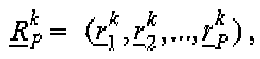 Erhalten einer Kanalimpulsgangfolge mit einer Länge P durch die Formel
wo k=1,...,N, und S ein konstanter Vektor ist;Berechnen der Interpolationsfunktion des Spitzenwerts zwischen den Kanalsehätzungsergebnissen
 Multiplizieren von CIRk mit dem Empfangskompensationskoeffizienten
 Berechnen der mittleren Leistung einer Enapfangsstrecke mit der Formel:
 Berechnen eines Empfangskompeensationskoeffizienten einer jeden Empfangsstrecke mit der Formel:
- Verfahren nach Anspruch 9, worin das Eliminieren aus der Folge von einem Abschnitt mit einer Länge gleich der Länge P der Basiskalibrierfolge durch Eliminieren eines Teils der Folge ausgeführt wird, wie durch folgende Formel dargestellt ist

- Verfahren nach Anspruch 9, worin der konstante Vektor S mit der Formel

berechnet wird, wo der komplexe Vektor der Kalibrierfolge m P = ( m 1, m 2,..., m P ) durch eine Pbasenentzerrung an der Basiskalibnerfolge m P ≃ (m 1,m 2,...,mP ) erzeugt wird, wo das Element der Folge m i = (j)i-1. m i ist mit i = 1,...,P, P = w×N die Länge der Basiskalibrierfolge darstellt, N die Anzahl der Antennenelement der intelligenten Antennengruppe ist und w die Fensterlänge der Kanalschätzung einer jeden Empfangsstrecke ist.
Applications Claiming Priority (3)
| Application Number | Priority Date | Filing Date | Title |
|---|---|---|---|
| CNB021586233A CN1176555C (zh) | 2002-12-25 | 2002-12-25 | 一种对智能天线阵系统进行实时校准的方法 |
| CN02158623 | 2002-12-25 | ||
| PCT/CN2003/001118 WO2004059868A1 (fr) | 2002-12-25 | 2003-12-25 | Procede d'etalonnage de systemes de reseaux d'antennes intelligents en temps reel |
Publications (3)
| Publication Number | Publication Date |
|---|---|
| EP1585231A1 EP1585231A1 (de) | 2005-10-12 |
| EP1585231A4 EP1585231A4 (de) | 2006-12-06 |
| EP1585231B1 true EP1585231B1 (de) | 2009-10-07 |
Family
ID=27811378
Family Applications (1)
| Application Number | Title | Priority Date | Filing Date |
|---|---|---|---|
| EP03782075A Expired - Lifetime EP1585231B1 (de) | 2002-12-25 | 2003-12-25 | Verfahren zur kalibrierung intelligenter antennengruppensysteme in echtzeit |
Country Status (9)
| Country | Link |
|---|---|
| US (1) | US7102569B2 (de) |
| EP (1) | EP1585231B1 (de) |
| JP (1) | JP4452628B2 (de) |
| KR (1) | KR100656979B1 (de) |
| CN (1) | CN1176555C (de) |
| AT (1) | ATE445264T1 (de) |
| AU (1) | AU2003292870A1 (de) |
| DE (1) | DE60329629D1 (de) |
| WO (1) | WO2004059868A1 (de) |
Families Citing this family (75)
| Publication number | Priority date | Publication date | Assignee | Title |
|---|---|---|---|---|
| EP1705807B1 (de) * | 2003-12-31 | 2017-10-25 | ZTE Corporation | Verfahren für eine gruppenantennen-übertragungsverbindung |
| CN100399719C (zh) * | 2005-02-03 | 2008-07-02 | 芯通科技(成都)有限公司 | 智能天线阵的校准方法和具有校准功能的射频收发信机 |
| US20060240784A1 (en) * | 2005-04-22 | 2006-10-26 | Qualcomm Incorporated | Antenna array calibration for wireless communication systems |
| US8498669B2 (en) | 2005-06-16 | 2013-07-30 | Qualcomm Incorporated | Antenna array calibration for wireless communication systems |
| US7672668B2 (en) * | 2005-09-07 | 2010-03-02 | Samsung Electronics Co., Ltd. | Calibration system architecture for calibrating multiple types of base stations in a wireless network |
| US8320903B2 (en) * | 2005-09-07 | 2012-11-27 | Samsung Electronics Co., Ltd. | Method and system for calibrating multiple types of base stations in a wireless network |
| US8280430B2 (en) | 2005-11-02 | 2012-10-02 | Qualcomm Incorporated | Antenna array calibration for multi-input multi-output wireless communication systems |
| US9118111B2 (en) | 2005-11-02 | 2015-08-25 | Qualcomm Incorporated | Antenna array calibration for wireless communication systems |
| US8295884B2 (en) * | 2005-11-22 | 2012-10-23 | Samsung Electronics Co., Ltd | Method and system for providing digital compensation and vector calibration for a base station in a wireless network |
| CN101064902B (zh) * | 2006-04-25 | 2010-11-10 | 大唐移动通信设备有限公司 | 实时校准智能天线的方法 |
| CN101080031B (zh) * | 2006-05-26 | 2011-02-02 | 大唐移动通信设备有限公司 | 基带拉远技术的智能天线校准系统及其方法 |
| CN101188448B (zh) * | 2006-11-15 | 2011-09-14 | 电信科学技术研究院 | 一种智能天线的校准方法、装置及系统 |
| US8055300B2 (en) * | 2007-08-29 | 2011-11-08 | Telefonaktiebolaget Lm Ericsson (Publ) | System and method for indoor coverage of user equipment terminals |
| EP2183820A1 (de) * | 2007-08-31 | 2010-05-12 | BAE Systems PLC | Antennenkalibration |
| WO2009027724A1 (en) * | 2007-08-31 | 2009-03-05 | Bae Systems Plc | Antenna calibration |
| EP2183818A1 (de) | 2007-08-31 | 2010-05-12 | BAE Systems PLC | Antennenkalibration |
| DK2183817T3 (da) * | 2007-08-31 | 2017-11-27 | Bae Systems Plc | Antenne kalibrering |
| CN101383647B (zh) * | 2007-09-06 | 2012-01-11 | 电信科学技术研究院 | 对工作天线进行校准的方法及装置 |
| CN101227242B (zh) * | 2008-01-31 | 2011-06-01 | 西安交通大学 | 一种基于通道校正的分布式天线阵列波束形成方法 |
| JP4471006B2 (ja) | 2008-02-04 | 2010-06-02 | ソニー株式会社 | 無線通信装置、アンテナ較正方法、およびプログラム |
| CN101552994B (zh) * | 2008-04-02 | 2011-04-20 | 大唐移动通信设备有限公司 | 一种收校准和发校准错开的方法及装置 |
| GB2461082A (en) * | 2008-06-20 | 2009-12-23 | Ubidyne Inc | Antenna array calibration with reduced interference from a payload signal |
| JP5153507B2 (ja) * | 2008-08-04 | 2013-02-27 | 三菱電機株式会社 | 無線通信装置 |
| US8193971B2 (en) * | 2008-11-10 | 2012-06-05 | Motorola Mobility, Inc. | Antenna reciprocity calibration |
| US8489041B2 (en) * | 2009-06-08 | 2013-07-16 | Anthony Teillet | Multi-element amplitude and phase compensated antenna array with adaptive pre-distortion for wireless network |
| US8731005B2 (en) | 2009-10-12 | 2014-05-20 | Kathrein-Werke Kg | Absolute timing and Tx power calibration of the Tx path in a distributed system |
| KR101285388B1 (ko) * | 2009-12-18 | 2013-07-10 | 한국전자통신연구원 | 빔 조향 장치 |
| CN102136858B (zh) * | 2010-01-25 | 2014-07-02 | 中国移动通信集团公司 | 一种基站校准方法和校准装置 |
| CN102111202B (zh) * | 2010-02-05 | 2014-05-21 | 电信科学技术研究院 | 一种天线校准的方法及装置 |
| US8634766B2 (en) | 2010-02-16 | 2014-01-21 | Andrew Llc | Gain measurement and monitoring for wireless communication systems |
| US8374826B2 (en) | 2010-02-22 | 2013-02-12 | Ubidyne, Inc. | System, apparatus and method for calibrating a delay along a signal path |
| US8441966B2 (en) | 2010-03-31 | 2013-05-14 | Ubidyne Inc. | Active antenna array and method for calibration of receive paths in said array |
| US8311166B2 (en) | 2010-03-31 | 2012-11-13 | Ubidyne, Inc. | Active antenna array and method for calibration of the active antenna array |
| US8340612B2 (en) | 2010-03-31 | 2012-12-25 | Ubidyne, Inc. | Active antenna array and method for calibration of the active antenna array |
| US8774196B2 (en) | 2010-06-03 | 2014-07-08 | Kathrein-Werke Kg | Active antenna array and method for relaying radio signals with synchronous digital data interface |
| CN103026782B (zh) * | 2010-06-03 | 2016-05-04 | 诺基亚通信公司 | 基站校准 |
| US8599861B2 (en) | 2010-06-03 | 2013-12-03 | Kathrein-Werke Kg | Active antenna array and method for relaying radio signals |
| US8791767B2 (en) * | 2010-10-29 | 2014-07-29 | Qualcomm Incorporated | Package inductance compensating tunable capacitor circuit |
| CN102148636B (zh) * | 2011-01-27 | 2013-09-04 | 大唐移动通信设备有限公司 | 一种天线校准的方法和系统 |
| US9295006B2 (en) | 2011-02-09 | 2016-03-22 | Qualcomm Incorporated | Real-time calibration of an air to ground communication system |
| CN102651672B (zh) * | 2011-02-25 | 2015-02-04 | 中国移动通信集团公司 | 一种用于协作式mimo系统的基站校准方法及装置 |
| GB2489002A (en) * | 2011-03-14 | 2012-09-19 | Nujira Ltd | Delay adjustment to reduce distortion in an envelope tracking transmitter |
| CN102790636B (zh) * | 2011-05-17 | 2015-01-28 | 普天信息技术研究院有限公司 | 一种智能天线校准序列的发送方法 |
| US8970427B2 (en) | 2011-05-18 | 2015-03-03 | Mediatek Singapore Pte. Ltd. | Phase-arrayed device and method for calibrating the phase-arrayed device |
| US9319172B2 (en) | 2011-10-14 | 2016-04-19 | Qualcomm Incorporated | Interference mitigation techniques for air to ground systems |
| CN104205659A (zh) * | 2011-10-21 | 2014-12-10 | 奥普蒂斯蜂窝技术有限责任公司 | 阵列天线系统中的天线设备校准方法、处理装置、计算机程序、计算机程序产品和天线设备 |
| CN102497223B (zh) * | 2011-12-05 | 2014-01-15 | 北京北方烽火科技有限公司 | 一种td-lte天线阵列校准方法与装置 |
| CN102412917B (zh) * | 2011-12-16 | 2014-04-16 | 哈尔滨工业大学深圳研究生院 | 基于网络分析仪和射频开关的多天线测量系统及方法 |
| EP2896137B1 (de) * | 2012-09-13 | 2019-07-10 | Telefonaktiebolaget LM Ericsson (publ) | Verfahren und vorrichtung zur antennenkalibrierung |
| CN102932039B (zh) * | 2012-10-17 | 2015-03-25 | 大唐移动通信设备有限公司 | 一种天线校准方法和系统 |
| CN103916176B (zh) * | 2013-01-04 | 2018-08-10 | 中国移动通信集团公司 | 一种无线直放站及其天线校准方法 |
| CN103916168B (zh) * | 2013-01-04 | 2018-02-23 | 中国移动通信集团公司 | 一种天线校准方法及装置 |
| CN103117786B (zh) * | 2013-01-18 | 2015-10-07 | 大唐移动通信设备有限公司 | 一种天线阵列校准方法和系统 |
| JP6329348B2 (ja) * | 2013-08-13 | 2018-05-23 | 株式会社Nttドコモ | 基地局装置、およびキャリブレーション方法 |
| GB2517217B (en) * | 2013-08-16 | 2018-03-21 | Analog Devices Global | Communication unit, integrated circuit and method for generating a plurality of sectored beams |
| WO2016090548A1 (zh) * | 2014-12-09 | 2016-06-16 | 华为技术有限公司 | 一种确定校准权值系数的方法及基站 |
| KR101556067B1 (ko) | 2014-12-12 | 2015-10-13 | 한국항공우주연구원 | 어레이 안테나 송신장치 및 그 교정방법 |
| CN104702351B (zh) * | 2015-01-07 | 2017-05-17 | 成都九洲迪飞科技有限责任公司 | 天线校准方法 |
| GB2543563B (en) * | 2015-10-23 | 2020-02-12 | Cambium Networks Ltd | Method and Apparatus for Controlling Equivalent Isotropic Radiated Power |
| WO2017145257A1 (ja) * | 2016-02-23 | 2017-08-31 | 三菱電機株式会社 | アレーアンテナ装置およびその校正方法 |
| US10263330B2 (en) * | 2016-05-26 | 2019-04-16 | Nokia Solutions And Networks Oy | Antenna elements and apparatus suitable for AAS calibration by selective couplerline and TRX RF subgroups |
| DE102016212136A1 (de) * | 2016-07-04 | 2018-01-04 | Laird Bochum GmbH | Verfahren und Vorrichtung zur Bestimmung einer Distanz sowie Fahrzeug |
| JP6645369B2 (ja) | 2016-07-06 | 2020-02-14 | 富士通株式会社 | 無線通信システム、及び、基地局 |
| CN107782979B (zh) * | 2016-08-25 | 2019-04-09 | 西安电子科技大学 | 利用矢量网络分析仪检测电磁波涡旋态的方法及装置 |
| EP3293897B8 (de) | 2016-09-12 | 2020-08-12 | Rohde & Schwarz GmbH & Co. KG | System und verfahren zur charakterisierung von multi-element-antennen |
| EP3565134B1 (de) * | 2017-01-24 | 2020-08-05 | Huawei Technologies Co., Ltd. | Antennenkorrekturverfahren und -vorrichtung |
| US10128894B1 (en) * | 2017-05-09 | 2018-11-13 | Analog Devices Global | Active antenna calibration |
| WO2019153186A1 (zh) * | 2018-02-08 | 2019-08-15 | 上海诺基亚贝尔股份有限公司 | 一种对天线阵列进行盲校准的方法和装置 |
| CN110768701B (zh) * | 2018-07-27 | 2022-10-28 | 中兴通讯股份有限公司 | 信道状态处理方法及装置、系统、终端、基站、存储介质 |
| US11276928B1 (en) | 2019-04-10 | 2022-03-15 | The Governors Of The University Of Alberta | Calibrating/monitoring method and apparatus for phased array antenna employing very near field |
| CN110429993B (zh) * | 2019-06-17 | 2022-01-25 | 北京睿信丰科技有限公司 | 一种宽频单载波天线校准方法及校准系统 |
| WO2020256607A1 (en) * | 2019-06-20 | 2020-12-24 | Telefonaktiebolaget Lm Ericsson (Publ) | Network node and method in a wireless communications network |
| CN111490835B (zh) * | 2020-03-05 | 2022-08-26 | 西安宇飞电子技术有限公司 | 一种窄带信号自校准方法、装置及设备 |
| WO2021191957A1 (ja) * | 2020-03-23 | 2021-09-30 | 三菱電機株式会社 | アレーアンテナの校正装置および校正方法 |
| CN115913404A (zh) * | 2021-09-30 | 2023-04-04 | 深圳市中兴微电子技术有限公司 | 天线校准方法、装置和远程射频单元 |
Family Cites Families (9)
| Publication number | Priority date | Publication date | Assignee | Title |
|---|---|---|---|---|
| US5546090A (en) * | 1991-12-12 | 1996-08-13 | Arraycomm, Inc. | Method and apparatus for calibrating antenna arrays |
| JPH10503892A (ja) * | 1994-06-03 | 1998-04-07 | テレフオンアクチーボラゲツト エル エム エリクソン | アンテナアレイの校正 |
| US6157343A (en) * | 1996-09-09 | 2000-12-05 | Telefonaktiebolaget Lm Ericsson | Antenna array calibration |
| US5682165A (en) * | 1996-05-02 | 1997-10-28 | Hughes Electronics | Active array self calibration |
| CN1118146C (zh) * | 1999-08-10 | 2003-08-13 | 信息产业部电信科学技术研究院 | 一种校准智能天线阵的方法和装置 |
| US6236839B1 (en) * | 1999-09-10 | 2001-05-22 | Utstarcom, Inc. | Method and apparatus for calibrating a smart antenna array |
| JP4303373B2 (ja) * | 1999-09-14 | 2009-07-29 | 株式会社日立コミュニケーションテクノロジー | 無線基地局装置 |
| CN1170450C (zh) * | 2002-09-13 | 2004-10-06 | 大唐移动通信设备有限公司 | 对智能天线阵进行实时校准的方法 |
| US6720919B1 (en) * | 2002-09-20 | 2004-04-13 | Lucent Technologies Inc. | Phased array calibration using sparse arbitrarily spaced rotating electric vectors and a scalar measurement system |
-
2002
- 2002-12-25 CN CNB021586233A patent/CN1176555C/zh not_active Expired - Lifetime
-
2003
- 2003-12-25 AU AU2003292870A patent/AU2003292870A1/en not_active Abandoned
- 2003-12-25 JP JP2004562467A patent/JP4452628B2/ja not_active Expired - Lifetime
- 2003-12-25 WO PCT/CN2003/001118 patent/WO2004059868A1/zh not_active Ceased
- 2003-12-25 EP EP03782075A patent/EP1585231B1/de not_active Expired - Lifetime
- 2003-12-25 AT AT03782075T patent/ATE445264T1/de not_active IP Right Cessation
- 2003-12-25 DE DE60329629T patent/DE60329629D1/de not_active Expired - Lifetime
- 2003-12-25 KR KR1020057011989A patent/KR100656979B1/ko not_active Expired - Lifetime
-
2005
- 2005-06-23 US US11/166,514 patent/US7102569B2/en not_active Expired - Lifetime
Also Published As
| Publication number | Publication date |
|---|---|
| US20060009162A1 (en) | 2006-01-12 |
| EP1585231A1 (de) | 2005-10-12 |
| KR100656979B1 (ko) | 2006-12-13 |
| CN1176555C (zh) | 2004-11-17 |
| EP1585231A4 (de) | 2006-12-06 |
| KR20050089853A (ko) | 2005-09-08 |
| CN1446000A (zh) | 2003-10-01 |
| US7102569B2 (en) | 2006-09-05 |
| AU2003292870A1 (en) | 2004-07-22 |
| JP2006512807A (ja) | 2006-04-13 |
| JP4452628B2 (ja) | 2010-04-21 |
| ATE445264T1 (de) | 2009-10-15 |
| DE60329629D1 (de) | 2009-11-19 |
| WO2004059868A1 (fr) | 2004-07-15 |
Similar Documents
| Publication | Publication Date | Title |
|---|---|---|
| EP1585231B1 (de) | Verfahren zur kalibrierung intelligenter antennengruppensysteme in echtzeit | |
| US6480153B1 (en) | Calibration apparatus of adaptive array antenna and calibration method thereof | |
| EP1085684B1 (de) | Funkbasisstation mit Gruppenantenne und Sendekalibrierung | |
| US9300382B2 (en) | Wireless signal processor and wireless apparatus | |
| RU2265263C2 (ru) | Способ и устройство для калибровки решетки интеллектуальной антенны | |
| EP1329983B1 (de) | Anordnung und Methode zur Kalibrierung einer Gruppenantenne | |
| EP1670094B1 (de) | Verfahren zur Kalibrierung eines intelligenten Gruppenantennensystems | |
| EP1433271B1 (de) | Kalibrierung eines funkkommunikationssystems | |
| EP1438768B1 (de) | Frequenzabhängige kalibration eines breitbandfunksystems mit schmalbandkanälen | |
| US6735182B1 (en) | Adaptive array antenna system | |
| US6317612B1 (en) | Method for estimating spatial parameters of transmission channels by estimating a spatial covariance matrix | |
| US6847805B2 (en) | Method for closed-loop subspace transmission and reception in a two transmit N-receive antenna system | |
| US8295869B2 (en) | Method and apparatus for improving transmission efficiency in a mobile radio communications system | |
| US7944891B2 (en) | Frequency transformation based transmit beamforming in a communication system | |
| EP1087545A1 (de) | Verfahren zur Abwärtsrichtstrahlbildung | |
| US8219035B2 (en) | Enhanced calibration for multiple signal processing paths in a wireless network | |
| US5710977A (en) | Apparatus for measuring multipath propagation characteristics | |
| EP1187254B1 (de) | Adaptives Antennensteuerungsverfahren und adaptives Steuerungsverfahren der Antennen- Sende/Empfangscharakteristik | |
| KR100375826B1 (ko) | 배열 안테나를 이용한 대역 확산 코드 분할 다중 접속기지국 시스템의 순방향 빔 형성 가중치 연산 장치, 이를이용한 순방향 빔 형성 시스템 및 그 방법 | |
| CN100397806C (zh) | 移动通信系统中用于校准接收信号的方法和装置 | |
| US20040048580A1 (en) | Base transceiver station | |
| EP3618314B1 (de) | Kalibrierungssystem, antennensystem und verfahren | |
| US8179314B2 (en) | Enhanced calibration for multiple signal processing paths in a frequency division duplex system | |
| CN111181617A (zh) | 一种发射波束的形成方法 |
Legal Events
| Date | Code | Title | Description |
|---|---|---|---|
| PUAI | Public reference made under article 153(3) epc to a published international application that has entered the european phase |
Free format text: ORIGINAL CODE: 0009012 |
|
| 17P | Request for examination filed |
Effective date: 20050725 |
|
| AK | Designated contracting states |
Kind code of ref document: A1 Designated state(s): AT BE BG CH CY CZ DE DK EE ES FI FR GB GR HU IE IT LI LU MC NL PT RO SE SI SK TR |
|
| AX | Request for extension of the european patent |
Extension state: AL LT LV MK |
|
| DAX | Request for extension of the european patent (deleted) | ||
| A4 | Supplementary search report drawn up and despatched |
Effective date: 20061106 |
|
| 17Q | First examination report despatched |
Effective date: 20070411 |
|
| GRAP | Despatch of communication of intention to grant a patent |
Free format text: ORIGINAL CODE: EPIDOSNIGR1 |
|
| GRAS | Grant fee paid |
Free format text: ORIGINAL CODE: EPIDOSNIGR3 |
|
| GRAA | (expected) grant |
Free format text: ORIGINAL CODE: 0009210 |
|
| AK | Designated contracting states |
Kind code of ref document: B1 Designated state(s): AT BE BG CH CY CZ DE DK EE ES FI FR GB GR HU IE IT LI LU MC NL PT RO SE SI SK TR |
|
| REG | Reference to a national code |
Ref country code: GB Ref legal event code: FG4D |
|
| REG | Reference to a national code |
Ref country code: CH Ref legal event code: EP |
|
| REG | Reference to a national code |
Ref country code: IE Ref legal event code: FG4D |
|
| REF | Corresponds to: |
Ref document number: 60329629 Country of ref document: DE Date of ref document: 20091119 Kind code of ref document: P |
|
| PG25 | Lapsed in a contracting state [announced via postgrant information from national office to epo] |
Ref country code: SI Free format text: LAPSE BECAUSE OF FAILURE TO SUBMIT A TRANSLATION OF THE DESCRIPTION OR TO PAY THE FEE WITHIN THE PRESCRIBED TIME-LIMIT Effective date: 20091007 |
|
| NLV1 | Nl: lapsed or annulled due to failure to fulfill the requirements of art. 29p and 29m of the patents act | ||
| PG25 | Lapsed in a contracting state [announced via postgrant information from national office to epo] |
Ref country code: SE Free format text: LAPSE BECAUSE OF FAILURE TO SUBMIT A TRANSLATION OF THE DESCRIPTION OR TO PAY THE FEE WITHIN THE PRESCRIBED TIME-LIMIT Effective date: 20091007 Ref country code: FI Free format text: LAPSE BECAUSE OF FAILURE TO SUBMIT A TRANSLATION OF THE DESCRIPTION OR TO PAY THE FEE WITHIN THE PRESCRIBED TIME-LIMIT Effective date: 20091007 Ref country code: ES Free format text: LAPSE BECAUSE OF FAILURE TO SUBMIT A TRANSLATION OF THE DESCRIPTION OR TO PAY THE FEE WITHIN THE PRESCRIBED TIME-LIMIT Effective date: 20100118 Ref country code: PT Free format text: LAPSE BECAUSE OF FAILURE TO SUBMIT A TRANSLATION OF THE DESCRIPTION OR TO PAY THE FEE WITHIN THE PRESCRIBED TIME-LIMIT Effective date: 20100208 |
|
| PG25 | Lapsed in a contracting state [announced via postgrant information from national office to epo] |
Ref country code: BE Free format text: LAPSE BECAUSE OF FAILURE TO SUBMIT A TRANSLATION OF THE DESCRIPTION OR TO PAY THE FEE WITHIN THE PRESCRIBED TIME-LIMIT Effective date: 20091007 Ref country code: AT Free format text: LAPSE BECAUSE OF FAILURE TO SUBMIT A TRANSLATION OF THE DESCRIPTION OR TO PAY THE FEE WITHIN THE PRESCRIBED TIME-LIMIT Effective date: 20091007 |
|
| PG25 | Lapsed in a contracting state [announced via postgrant information from national office to epo] |
Ref country code: DK Free format text: LAPSE BECAUSE OF FAILURE TO SUBMIT A TRANSLATION OF THE DESCRIPTION OR TO PAY THE FEE WITHIN THE PRESCRIBED TIME-LIMIT Effective date: 20091007 Ref country code: NL Free format text: LAPSE BECAUSE OF FAILURE TO SUBMIT A TRANSLATION OF THE DESCRIPTION OR TO PAY THE FEE WITHIN THE PRESCRIBED TIME-LIMIT Effective date: 20091007 Ref country code: RO Free format text: LAPSE BECAUSE OF FAILURE TO SUBMIT A TRANSLATION OF THE DESCRIPTION OR TO PAY THE FEE WITHIN THE PRESCRIBED TIME-LIMIT Effective date: 20091007 Ref country code: MC Free format text: LAPSE BECAUSE OF NON-PAYMENT OF DUE FEES Effective date: 20100701 Ref country code: BG Free format text: LAPSE BECAUSE OF FAILURE TO SUBMIT A TRANSLATION OF THE DESCRIPTION OR TO PAY THE FEE WITHIN THE PRESCRIBED TIME-LIMIT Effective date: 20100107 Ref country code: EE Free format text: LAPSE BECAUSE OF FAILURE TO SUBMIT A TRANSLATION OF THE DESCRIPTION OR TO PAY THE FEE WITHIN THE PRESCRIBED TIME-LIMIT Effective date: 20091007 |
|
| REG | Reference to a national code |
Ref country code: CH Ref legal event code: PL |
|
| PLBE | No opposition filed within time limit |
Free format text: ORIGINAL CODE: 0009261 |
|
| STAA | Information on the status of an ep patent application or granted ep patent |
Free format text: STATUS: NO OPPOSITION FILED WITHIN TIME LIMIT |
|
| PG25 | Lapsed in a contracting state [announced via postgrant information from national office to epo] |
Ref country code: SK Free format text: LAPSE BECAUSE OF FAILURE TO SUBMIT A TRANSLATION OF THE DESCRIPTION OR TO PAY THE FEE WITHIN THE PRESCRIBED TIME-LIMIT Effective date: 20091007 Ref country code: CZ Free format text: LAPSE BECAUSE OF FAILURE TO SUBMIT A TRANSLATION OF THE DESCRIPTION OR TO PAY THE FEE WITHIN THE PRESCRIBED TIME-LIMIT Effective date: 20091007 |
|
| 26N | No opposition filed |
Effective date: 20100708 |
|
| PG25 | Lapsed in a contracting state [announced via postgrant information from national office to epo] |
Ref country code: GR Free format text: LAPSE BECAUSE OF FAILURE TO SUBMIT A TRANSLATION OF THE DESCRIPTION OR TO PAY THE FEE WITHIN THE PRESCRIBED TIME-LIMIT Effective date: 20100108 Ref country code: LI Free format text: LAPSE BECAUSE OF NON-PAYMENT OF DUE FEES Effective date: 20091231 Ref country code: CH Free format text: LAPSE BECAUSE OF NON-PAYMENT OF DUE FEES Effective date: 20091231 Ref country code: IE Free format text: LAPSE BECAUSE OF NON-PAYMENT OF DUE FEES Effective date: 20091225 |
|
| PG25 | Lapsed in a contracting state [announced via postgrant information from national office to epo] |
Ref country code: IT Free format text: LAPSE BECAUSE OF FAILURE TO SUBMIT A TRANSLATION OF THE DESCRIPTION OR TO PAY THE FEE WITHIN THE PRESCRIBED TIME-LIMIT Effective date: 20091007 |
|
| PG25 | Lapsed in a contracting state [announced via postgrant information from national office to epo] |
Ref country code: LU Free format text: LAPSE BECAUSE OF NON-PAYMENT OF DUE FEES Effective date: 20091225 |
|
| PG25 | Lapsed in a contracting state [announced via postgrant information from national office to epo] |
Ref country code: HU Free format text: LAPSE BECAUSE OF FAILURE TO SUBMIT A TRANSLATION OF THE DESCRIPTION OR TO PAY THE FEE WITHIN THE PRESCRIBED TIME-LIMIT Effective date: 20100408 |
|
| REG | Reference to a national code |
Ref country code: DE Ref legal event code: R081 Ref document number: 60329629 Country of ref document: DE Owner name: CHINA ACADEMY OF TELECOMMUNICATIONS TECHNOLOGY, CN Free format text: FORMER OWNER: DA TANG MOBILE COMMUNICATIONS EQUIPMENT CO., LTD., PEKING/BEI-JING, CN Effective date: 20110701 Ref country code: DE Ref legal event code: R082 Ref document number: 60329629 Country of ref document: DE Representative=s name: MARKS & CLERK (LUXEMBOURG) LLP, LU Effective date: 20110701 |
|
| PG25 | Lapsed in a contracting state [announced via postgrant information from national office to epo] |
Ref country code: TR Free format text: LAPSE BECAUSE OF FAILURE TO SUBMIT A TRANSLATION OF THE DESCRIPTION OR TO PAY THE FEE WITHIN THE PRESCRIBED TIME-LIMIT Effective date: 20091007 |
|
| REG | Reference to a national code |
Ref country code: GB Ref legal event code: 732E Free format text: REGISTERED BETWEEN 20110804 AND 20110810 |
|
| PG25 | Lapsed in a contracting state [announced via postgrant information from national office to epo] |
Ref country code: CY Free format text: LAPSE BECAUSE OF FAILURE TO SUBMIT A TRANSLATION OF THE DESCRIPTION OR TO PAY THE FEE WITHIN THE PRESCRIBED TIME-LIMIT Effective date: 20091007 |
|
| REG | Reference to a national code |
Ref country code: FR Ref legal event code: PLFP Year of fee payment: 13 |
|
| REG | Reference to a national code |
Ref country code: FR Ref legal event code: PLFP Year of fee payment: 14 |
|
| REG | Reference to a national code |
Ref country code: FR Ref legal event code: PLFP Year of fee payment: 15 |
|
| REG | Reference to a national code |
Ref country code: DE Ref legal event code: R081 Ref document number: 60329629 Country of ref document: DE Owner name: DATANG MOBILE COMMUNICATIONS EQUIPMENT CO., LT, CN Free format text: FORMER OWNER: CHINA ACADEMY OF TELECOMMUNICATIONS TECHNOLOGY, BEIJING, CN |
|
| REG | Reference to a national code |
Ref country code: GB Ref legal event code: 732E Free format text: REGISTERED BETWEEN 20210729 AND 20210804 |
|
| PGFP | Annual fee paid to national office [announced via postgrant information from national office to epo] |
Ref country code: GB Payment date: 20221222 Year of fee payment: 20 Ref country code: FR Payment date: 20221222 Year of fee payment: 20 Ref country code: DE Payment date: 20221213 Year of fee payment: 20 |
|
| REG | Reference to a national code |
Ref country code: DE Ref legal event code: R071 Ref document number: 60329629 Country of ref document: DE |
|
| REG | Reference to a national code |
Ref country code: GB Ref legal event code: PE20 Expiry date: 20231224 |
|
| PG25 | Lapsed in a contracting state [announced via postgrant information from national office to epo] |
Ref country code: GB Free format text: LAPSE BECAUSE OF EXPIRATION OF PROTECTION Effective date: 20231224 |
|
| PG25 | Lapsed in a contracting state [announced via postgrant information from national office to epo] |
Ref country code: GB Free format text: LAPSE BECAUSE OF EXPIRATION OF PROTECTION Effective date: 20231224 |