EP1584839A1 - Torsionsschwingungsdämpfer - Google Patents
Torsionsschwingungsdämpfer Download PDFInfo
- Publication number
- EP1584839A1 EP1584839A1 EP04008581A EP04008581A EP1584839A1 EP 1584839 A1 EP1584839 A1 EP 1584839A1 EP 04008581 A EP04008581 A EP 04008581A EP 04008581 A EP04008581 A EP 04008581A EP 1584839 A1 EP1584839 A1 EP 1584839A1
- Authority
- EP
- European Patent Office
- Prior art keywords
- torsional vibration
- vibration damper
- shoe
- driver
- spring element
- Prior art date
- Legal status (The legal status is an assumption and is not a legal conclusion. Google has not performed a legal analysis and makes no representation as to the accuracy of the status listed.)
- Granted
Links
- 230000007935 neutral effect Effects 0.000 claims description 5
- 239000000969 carrier Substances 0.000 abstract description 2
- 241000288726 Soricidae Species 0.000 abstract 1
- 238000013016 damping Methods 0.000 description 8
- 230000005540 biological transmission Effects 0.000 description 7
- 238000002485 combustion reaction Methods 0.000 description 4
- 230000006835 compression Effects 0.000 description 3
- 238000007906 compression Methods 0.000 description 3
- 238000011161 development Methods 0.000 description 3
- 230000018109 developmental process Effects 0.000 description 3
- 238000000034 method Methods 0.000 description 3
- 230000008569 process Effects 0.000 description 3
- 230000006378 damage Effects 0.000 description 2
- 230000000694 effects Effects 0.000 description 2
- 238000010009 beating Methods 0.000 description 1
- 230000009286 beneficial effect Effects 0.000 description 1
- 230000008901 benefit Effects 0.000 description 1
- 230000008859 change Effects 0.000 description 1
- 230000008878 coupling Effects 0.000 description 1
- 238000010168 coupling process Methods 0.000 description 1
- 238000005859 coupling reaction Methods 0.000 description 1
- 230000000881 depressing effect Effects 0.000 description 1
- 239000000446 fuel Substances 0.000 description 1
- 230000002093 peripheral effect Effects 0.000 description 1
- 230000009467 reduction Effects 0.000 description 1
- 230000035939 shock Effects 0.000 description 1
- 125000006850 spacer group Chemical group 0.000 description 1
- 238000004804 winding Methods 0.000 description 1
Images

Classifications
-
- F—MECHANICAL ENGINEERING; LIGHTING; HEATING; WEAPONS; BLASTING
- F16—ENGINEERING ELEMENTS AND UNITS; GENERAL MEASURES FOR PRODUCING AND MAINTAINING EFFECTIVE FUNCTIONING OF MACHINES OR INSTALLATIONS; THERMAL INSULATION IN GENERAL
- F16F—SPRINGS; SHOCK-ABSORBERS; MEANS FOR DAMPING VIBRATION
- F16F15/00—Suppression of vibrations in systems; Means or arrangements for avoiding or reducing out-of-balance forces, e.g. due to motion
- F16F15/10—Suppression of vibrations in rotating systems by making use of members moving with the system
- F16F15/12—Suppression of vibrations in rotating systems by making use of members moving with the system using elastic members or friction-damping members, e.g. between a rotating shaft and a gyratory mass mounted thereon
- F16F15/131—Suppression of vibrations in rotating systems by making use of members moving with the system using elastic members or friction-damping members, e.g. between a rotating shaft and a gyratory mass mounted thereon the rotating system comprising two or more gyratory masses
- F16F15/133—Suppression of vibrations in rotating systems by making use of members moving with the system using elastic members or friction-damping members, e.g. between a rotating shaft and a gyratory mass mounted thereon the rotating system comprising two or more gyratory masses using springs as elastic members, e.g. metallic springs
- F16F15/134—Wound springs
- F16F15/1343—Wound springs characterised by the spring mounting
- F16F15/13453—Additional guiding means for springs
-
- F—MECHANICAL ENGINEERING; LIGHTING; HEATING; WEAPONS; BLASTING
- F16—ENGINEERING ELEMENTS AND UNITS; GENERAL MEASURES FOR PRODUCING AND MAINTAINING EFFECTIVE FUNCTIONING OF MACHINES OR INSTALLATIONS; THERMAL INSULATION IN GENERAL
- F16F—SPRINGS; SHOCK-ABSORBERS; MEANS FOR DAMPING VIBRATION
- F16F15/00—Suppression of vibrations in systems; Means or arrangements for avoiding or reducing out-of-balance forces, e.g. due to motion
- F16F15/10—Suppression of vibrations in rotating systems by making use of members moving with the system
- F16F15/12—Suppression of vibrations in rotating systems by making use of members moving with the system using elastic members or friction-damping members, e.g. between a rotating shaft and a gyratory mass mounted thereon
- F16F15/121—Suppression of vibrations in rotating systems by making use of members moving with the system using elastic members or friction-damping members, e.g. between a rotating shaft and a gyratory mass mounted thereon using springs as elastic members, e.g. metallic springs
- F16F15/123—Wound springs
- F16F15/1232—Wound springs characterised by the spring mounting
- F16F15/1234—Additional guiding means for springs, e.g. for support along the body of springs that extend circumferentially over a significant length
Definitions
- the invention relates to a torsional vibration damper a drive having at least one Primärmitolitary Primary element and at least one secondary driver having output side secondary element, the opposite at least one between one of the primary drivers and one of the Sekundärmit predominantly provided spring element around a Neutral position are rotatable relative to each other, as well as with end of the spring elements arranged end shoes, wherein at least one of the end shoes is designed such that upon reaching a threshold relative rotation angle with respect to Neutral position of at least one of the drivers bypassing the at least one shoe in direct contact with the spring element occurs.
- Torsional vibration dampers or torsional vibration dampers are in different variations and from different applications known. In particular, they are in the automotive industry to elastic coupling of internal combustion engine and drive train intended. This is to prevent that vibrations from the side of the internal combustion engine transmitted to the drive train or the transmission become. Such a transmission of the vibrations is at Motor vehicle drives, especially in internal combustion engines with comparatively few cylinders and at low Given speeds. An effective damping of such Vibrations causes lower speeds of rotation Internal combustion engine can be driven, which in general results in a reduced fuel consumption and therefore both economically and ecologically beneficial is.
- Torsional vibration damper with a drive-side primary element and a driven-side secondary element, which coupled together via a spring device and one Rotation axis limited against each other are rotatable are for example from EP 1 371 875 A1 or DE 195 22 718 A1 known.
- the primary element comprises a first one below driver referred to as the primary driver; the secondary element includes a second subsequently as a secondary driver designated driver.
- the torque is from the primary element by means of the Primärmit ceremonies first on the spring device and from there to the secondary driver of the secondary element transfer.
- the spring device consists i.d.R. from one or more in Circumferential direction of the torsional vibration damper in a row arranged spring elements, preferably coil springs or Coil spring sets, if necessary by sliding shoes connected to each other, and on both sides via end shoes are supported against the respective carriers. Done one Moment transfer from primary element to secondary element, so the torque transmission described is referred to as train. If the torque transmission is the other way around from the secondary element to the primary element, so is by thrust the speech.
- the invention is thus based on the problem without additional Components cost a torsional vibration damper to provide in which transfer noise at Tension / thrust changes in both large and small angular momentum or torques of the driver can be avoided.
- the invention is based on the idea of the torsional vibration damper fitted with end-pieces designed like this are that they continue to manage the spring elements, however, at no time of the damping process directly come into contact with the associated driver, but this instead always immediately preferably on the front page impinges the respective spring element. Steam it the spring elements the impact movement of the driver, so that regardless of the angular momentum of the driver no transfer noise occur.
- Such a shoe is thus designed such that the at least one driver in direct contact with the spring element remains as long as the threshold relative rotation angle is exceeded.
- the corresponding driver be designed such that the at least a driver in direct contact with the spring element remains as long as the threshold relative rotation angle is exceeded is. It therefore always finds a torque transmission from the driver to the spring element, unlike in DE 199 58 814 Al, where from a threshold relative rotation angle a torque transmission from the driver to the shoe and takes place from the shoe to the spring element.
- the invention provides that the at least one end shoe is a recess has, through which the corresponding driver can be passed is, and which is such that the driver during a damping process through this recess therethrough meets the spring element, but never with the shoe comes into contact.
- the shoe has an open perpendicular to the direction of damping Structure on. That is, the end face of the spring element Covering side surface of the shoe is not as annular executed closed area, but for example U or V-shaped. In this way, the driver along the inner wall of by a front and a rear Side window formed cavity are guided and the end shoe penetrate over the entire surface.
- the end shoe in question can also be perpendicular to the direction of rotation be formed in cross-section L-shaped. Now will the corresponding driver preferably on the one leg passed the L-shape.
- an advantageous development of the invention is the at least one end shoe with at least one device to provide the attachment of the shoe to the spring element allows.
- this device is a retaining lug executed, with the turns of at least one coil spring the associated spring element can be clamped. To this This will prevent the shoe from becoming worn during the process Damping operation releases from the spring element and the spring element loses his leadership.
- the spring element of several consists of different, coiled coil springs, can in particular provided fastening devices Be the one who uses the shoe with different coil springs connect.
- the end shoes not on the spring elements, but on the drivers attached to the primary or secondary element and the end shoes each with at least one stop device for provided the associated spring element, preferably as a stop lug is executed.
- These stop devices serve the torque transmission from the spring elements to the with provided with the end shoes driver.
- An advantageous development of the invention is the shoe at its the axis of rotation of the torsional vibration damper facing away from the side with a sliding surface. This prevents - especially at a high speed of the primary element or secondary element - that due to Centrifugal forces windings of the respective spring element after on the outside against the wall of the arched side windows and the leadership of the spring elements and the driver be pressed depressing cavity and tilt there. Such tilting would result in damping the rotational movement only the spring travel from the point of Tilting to the end shoe, on which the driver hits, would be available. Vibration shares over this reduced travel can not be damped transmitted undamped.
- the spring element at least partially encloses, as z. B. at a End shoe with U-shaped cross section is the case. hereby results in an improved leadership of the spring element.
- end shoe and the possibly existing Sliding shoes advantageously made of plastic. This has the advantage of cost-effective manufacturability on the one hand, on the other hand, it is easy to get one low sliding friction at the contact sliding / end shoe to the lateral surface of the secondary element.
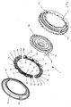
- a torsional vibration damper 3 is shown with a primary element in the form of a middle plate 26 and with a secondary element in the form of two rotatably connected to each other Side windows 24, 26 shown.
- To the middle disk 26 are in one through the rear side window 24 and formed by the front side window 25 cavity from several spring sets 5, 6, 7, 8, 9, 10, 11, 12, 13, 14, 15, 16 arranged existing spring elements.
- Each of the spring sets 5, 6, 7, 8, 9, 10, 11, 12, 13, 14, 15, 16 consists in present embodiment of two nested Coil springs.
- the spring sets 5, 6, 7, 8, 9, 10 and 11, 12, 13, 14, 15, 16 are by spacers, so-called Sliding shoes 28, 29, 30, 31, 32 and 33, 34, 35, 36, 37 respectively a spring element forming successively lined up.
- At the respective End of a spring element is an end shoe 18a, 18b, 18c, 18d arranged.
- the end faces of the end shoes 18a, 18b, 18c, 18d sit in a neutral position in each case on a two-part executed here
- the End shoes 18a, 18b, 18c, 18d are U-shaped at their front sides executed.
- the two legs of the U-shape sit there essentially positively on the respective driver, consisting of the two partial drivers 17a, 17a 'and 17b, respectively, 17b ', of the secondary element.
- the space between the two legs of the U-shape of the respective end shoe 18a, 18b, 18c, 18d is just chosen so large that the driver 19b of the primary element 26 at a Relative rotation between primary and secondary element 24, 25, 26 meets in a direction of rotation directly on the spring set 14, without touching the end shoe 18b and that at the same time the Driver 19a of the primary element 26 directly on the spring set 10 hits without touching the end shoe 18c.
- sliding surfaces 27a, 27b, 27c, 27d of the end shoes 18a, 18b, 18c, 18d and not provided with reference numerals sliding surfaces the sliding blocks 28, 29, 30, 31, 32, 33, 34, 35, 36, 37 make sure that the spring sets 5, 6, 7, 8, 9, 10, 11, 12, 13, 14, 15, 16 under low friction and without Tilting compressed when primary and secondary elements 24, 25, 26 are rotated against each other. Furthermore is its circumferential extent in the present embodiment so dimensioned that their facing faces come into shock contact before the individual coil springs the spring sets 5, 6, 7, 8, 9, 10, 11, 12, 13, 14, 15, 16 go to block. They thus set the maximum compression ⁇ of Spring sets 5, 6, 7, 8, 9, 10, 11, 12, 13, 14, 15, 16 fixed. By this measure, a destruction of the coil springs prevented at high torques.
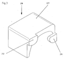
- FIG. 3 shows a perspective view Representation of such a shoe 218th
- the end shoe 218 is provided with two stop lugs 211, 212, which abutment points for the end face of the associated spring element form. They prevent the spring element with its end face through the end face of the shoe 218 after slides forward and the spring element so its leadership loses.
- On the axis of rotation of the torsional vibration damper facing away from the end shoe 218 has a sliding surface 227, on the inside of the spring element along slides.
- this sliding surface 227 is in the circumferential direction of the torsional vibration damper preferably so dimensioned that at maximum compression of the spring elements whose Ends further through the sliding surface 227 from the radially outer Part of the cavity to be shielded, allowing canting the spring coils on the cavity wall and the thus associated reduction of the damping effect is avoided.
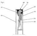
- FIG. 4 A cross section through the torsional vibration damper, at in which the end shoe 218 according to FIG. 3 is inserted, Figure 4 shows again.
- the front part of the driver of the secondary element 250 and the rear part of this Driver 251 together the driver of the secondary element.
- the end shoe 218 of Figure 3 is placed. He may optionally be attached. Its face is designed in a U-shape, so that the driver 219 of the primary element 210 can reach through the end shoe 218, without being in contact with it. Instead, it hits the driver 219 directly on the spring element 214, so that no transfer noise occurs.
- the cavity in which the spring elements move, is by joining the front side window 225 and rear side window 224 educated.
Landscapes
- Engineering & Computer Science (AREA)
- General Engineering & Computer Science (AREA)
- Physics & Mathematics (AREA)
- Acoustics & Sound (AREA)
- Aviation & Aerospace Engineering (AREA)
- Mechanical Engineering (AREA)
- Vibration Dampers (AREA)
Abstract
Description
- Figur 1
- einen Ausschnitt aus einem Torsionsschwingungsdämpfer mit einem ersten Ausführungsbeispiel erfindungsgemäß ausgebildeter Endschuhe,
- Figur 2
- den Torsionsschwingungsdämpfer gemäß Figur 1 in Explosionsdarstellung,
- Figur 3
- ein zweites Ausführungsbeispiel eines erfindungsgemäß ausgebildeten Endschuhs für einen Torsionsschwingungsdämpfer,
- Figur 4
- einen Querschnitt durch einen Torsionsschwingungsdämpfer mit Endschuhen gemäß der Figur 3.
- 3
- Torsionsschwingungsdämpfer
- 5
- Federsatz
- 6
- Federsatz
- 7
- Federsatz
- 8
- Federsatz
- 9
- Federsatz
- 10
- Federsatz
- 11
- Federsatz
- 12
- Federsatz
- 13
- Federsatz
- 14
- Federsatz
- 15
- Federsatz
- 16
- Federsatz
- 17a
- Mitnehmer Sekundärelement (Vorderteil)
- 17b
- Mitnehmer Sekundärelement (Vorderteil)
- 17a'
- Mitnehmer Sekundärelement (Hinterteil)
- 17b'
- Mitnehmer Sekundärelement (Hinterteil)
- 18a
- Endschuh
- 18b
- Endschuh
- 18c
- Endschuh
- 18d
- Endschuh
- 19a
- Mitnehmer Primärelement
- 19b
- Mitnehmer Primärelement
- 24
- hintere Seitenscheibe (Sekundärelement)
- 25
- vordere Seitenscheibe (Sekundärelement)
- 26
- Mittelscheibe (Primärelement)
- 27a
- Gleitfläche Endschuh
- 27b
- Gleitfläche Endschuh
- 27c
- Gleitfläche Endschuh
- 27d
- Gleitfläche Endschuh
- 28
- Gleitschuh
- 29
- Gleitschuh
- 30
- Gleitschuh
- 31
- Gleitschuh
- 32
- Gleitschuh
- 33
- Gleitschuh
- 34
- Gleitschuh
- 35
- Gleitschuh
- 36
- Gleitschuh
- 37
- Gleitschuh
- α
- maximale Stauchung
- 211
- Anschlagnase
- 212
- Anschlagnase
- 218
- Endschuh
- 227
- Gleitfläche Endschuh
- 210
- Primärelement
- 214
- Federelement
- 218
- Endschuh
- 219
- Mitnehmer Primärelement
- 224
- hintere Seitenscheibe (Sekundärelement)
- 225
- vordere Seitenscheibe (Sekundärelement)
- 250
- vorderer Teil Mitnehmer Sekundärelement
- 251
- hinterer Teil Mitnehmer Sekundärelement
Claims (11)
- Torsionsschwingungsdämpfer (3) mit einem mindestens einen Primärmitnehmer (19a, 19b; 219) aufweisenden antriebsseitigen Primärelement (26; 210) und einem mindestens einen Sekundärmitnehmer (17a, 17a'; 17b, 17b'; 250, 251) aufweisenden abtriebsseitigen Sekundärelement (24, 25; 224, 225), die entgegen mindestens einem zwischen einem der Primärmitnehmer (19, 19b; 219) und einem der Sekundärmitnehmer (17a, 17a'; 17b, 17b'; 250, 251) vorgesehenen Federelement (5, 6, 7, 8, 9, 10; 11, 12, 13, 14, 15, 16; 214) um eine Neutralposition relativ zueinander verdrehbar sind, sowie mit stirnseitig des jeweiligen Federelements (5, 6, 7, 8, 9, 10; 11, 12, 13, 14, 15, 16; 214) angeordneten Endschuhen (18a, 18b, 18c, 18d; 218), wobei wenigstens einer der Endschuhe (18a, 18b, 18c, 18d; 218) derart ausgebildet ist, dass bei Erreichen eines Schwellen-Relativdrehwinkels gegenüber der Neutralposition wenigstens einer der Mitnehmer (19a, 19b; 219) unter Umgehung des wenigstens einen Endschuhs (18a, 18b, 18c, 18d; 218) in direkten Kontakt mit dem Federelement (5, 6, 7, 8, 9, 10; 11, 12, 13, 14, 15, 16; 214) tritt,
dadurch gekennzeichnet, dass der wenigstens eine Endschuh (18a, 18b, 18c, 18d; 218) und/oder der wenigstens eine Mitnehmer (19a, 19b; 219) derart ausgebildet ist bzw. sind, dass der wenigstens eine Mitnehmer in direktem Kontakt mit dem Federelement (5, 6, 7, 8, 9, 10; 11, 12, 13, 14, 15, 16; 214) verbleibt, solange der Schwellen-Relativdrehwinkel überschritten ist. - Torsionsschwingungsdämpfer (3) nach Anspruch 1,
dadurch gekennzeichnet, dass der wenigstens eine Endschuh (18a, 18b, 18c, 18d; 218) eine Ausnehmung aufweist, durch welche der entsprechende Mitnehmer (19a, 19b; 219) hindurchführbar ist. - Torsionsschwingungsdämpfer (3) nach einem der vorangehenden Ansprüche,
dadurch gekennzeichnet, dass der wenigstens eine der Endschuhe (18a, 18b, 18c, 18d; 218) senkrecht zur Drehrichtung einen U-förmigen, V-förmigen oder L-förmigen Querschnitt aufweist und dass der wenigstens eine der Mitnehmer (19a, 19b; 219) durch die beiden Schenkel der U- oder V-Form hindurchführbar bzw. am einzigen Schenkel der L-Form vorbeiführbar ist. - Torsionsschwingungsdämpfer (3) nach einem der vorangegangenen Ansprüche,
dadurch gekennzeichnet, dass an dem wenigstens einen der Endschuhe (18a, 18b, 18c, 18d; 218) mindestens eine Vorrichtung zu dessen Befestigung am Federelement (5, 6, 7, 8, 9, 10; 11, 12, 13, 14, 15, 16; 214) vorgesehen ist, die vorzugsweise als Haltenase ausgeführt ist. - Torsionsschwingungsdämpfer (3) nach einem der vorangegangenen Ansprüche,
dadurch gekennzeichnet, dass an dem wenigstens einen der Endschuhe (18a, 18b, 18c, 18d; 218) eine Befestigungsvorrichtung angebracht ist, welche den wenigstens einen Endschuh (5, 6, 7, 8, 9, 10; 11, 12, 13, 14, 15, 16; 214) mit verschiedenen ineinander angeordneten Schraubenfedern des Federelements (5, 6, 7, 8, 9, 10; 11, 12, 13, 14, 15, 16; 214) verbinden. - Torsionsschwingungsdämpfer (3) nach einem der vorangegangenen Ansprüche,
dadurch gekennzeichnet, dass der wenigstens eine Endschuh (18a, 18b, 18c, 18d; 218) an wenigstens einem der anderen Mitnehmer (17a, 17a'; 17b, 17b'; 250, 251) befestigt ist. - Torsionsschwingungsdämpfer (3) nach einem der vorangegangenen Ansprüche,
dadurch gekennzeichnet, dass der wenigstens eine Endschuh (18a, 18b, 18c, 18d; 218) mindestens eine Anschlagvorrichtung für wenigstens eines der Federelemente (214) besitzt, welche vorzugsweise als Anschlagnase (211, 212) ausgeführt ist. - Torsionsschwingungsdämpfer (3) nach einem der vorangehenden Ansprüche,
dadurch gekennzeichnet, dass der wenigstens eine Endschuh (18a, 18b, 18c, 18d; 218) an seiner der Rotationsachse des Torsionsschwingungsdämpfers (3) abgewandten Seite eine Gleitfläche (27a, 27b, 27c, 27d; 227) aufweist. - Torsionsschwingungsdämpfer (3) nach einem der vorangehenden Ansprüche,
dadurch gekennzeichnet, dass bei dem wenigstens einen Endschuh (18a, 18b, 18c, 18d; 218) die der Mantelfläche des Federelements zugewandte Seite des Endschuhs (18a, 18b, 18c, 18d; 218) das Federelement (5, 6, 7, 8, 9, 10; 11, 12, 13, 14, 15, 16; 214) wenigstens teilweise umschließt. - Torsionsschwingungsdämpfer (3) nach einem der vorangehenden Ansprüche,
dadurch gekennzeichnet, dass der wenigstens eine der Endschuhe (18a, 18b, 18c, 18d; 218) aus Kunststoff gefertigt ist. - Endschuh (18a, 18b, 18c, 18d; 218) für einen Torsionsschwingungsdämpfer (3) nach einem der vorangegangenen Ansprüche.
Priority Applications (2)
| Application Number | Priority Date | Filing Date | Title |
|---|---|---|---|
| EP20040008581 EP1584839B1 (de) | 2004-04-08 | 2004-04-08 | Torsionsschwingungsdämpfer |
| DE200450005490 DE502004005490D1 (de) | 2004-04-08 | 2004-04-08 | Torsionsschwingungsdämpfer |
Applications Claiming Priority (1)
| Application Number | Priority Date | Filing Date | Title |
|---|---|---|---|
| EP20040008581 EP1584839B1 (de) | 2004-04-08 | 2004-04-08 | Torsionsschwingungsdämpfer |
Publications (2)
| Publication Number | Publication Date |
|---|---|
| EP1584839A1 true EP1584839A1 (de) | 2005-10-12 |
| EP1584839B1 EP1584839B1 (de) | 2007-11-14 |
Family
ID=34896034
Family Applications (1)
| Application Number | Title | Priority Date | Filing Date |
|---|---|---|---|
| EP20040008581 Expired - Lifetime EP1584839B1 (de) | 2004-04-08 | 2004-04-08 | Torsionsschwingungsdämpfer |
Country Status (2)
| Country | Link |
|---|---|
| EP (1) | EP1584839B1 (de) |
| DE (1) | DE502004005490D1 (de) |
Cited By (4)
| Publication number | Priority date | Publication date | Assignee | Title |
|---|---|---|---|---|
| WO2008071281A1 (de) | 2006-12-14 | 2008-06-19 | Borgwarner Inc. | Torsionsschwingungsdämpfer mit endschuhen und antriebsstrang mit einem solchen torsionsschwingungsdämpfer |
| DE102007022891A1 (de) | 2007-05-14 | 2008-11-20 | Borgwarner Inc., Auburn Hills | Schuh mit einer Federpositionsbegrenzung bzw. Torsionsschwingungsdämpfer mit einem solchen Schuh |
| CN113719552A (zh) * | 2021-08-12 | 2021-11-30 | 陕西航天动力高科技股份有限公司 | 一种离合器总成 |
| US20230193977A1 (en) * | 2020-05-11 | 2023-06-22 | Valeo Kapec Japan Kk | Torsional-vibration-reducing-device manufacturing method and torsional-vibration reducing device |
Citations (4)
| Publication number | Priority date | Publication date | Assignee | Title |
|---|---|---|---|---|
| DE19522718A1 (de) | 1994-07-01 | 1996-01-11 | Luk Lamellen & Kupplungsbau | Im Zusammenhang mit einer Reibungskupplung wirksame Drehmomentübertragungseinrichtung |
| DE19958814A1 (de) | 1999-12-07 | 2001-06-13 | Mannesmann Sachs Ag | Drehschwingungsdämpfer |
| DE10133694A1 (de) | 2000-07-27 | 2002-02-07 | Luk Lamellen & Kupplungsbau | Torsionsschwingungsdämpfer |
| EP1371875A1 (de) | 2002-06-15 | 2003-12-17 | Borgwarner, Inc. | Vorrichtung zur Dämpfung von Drehschwingungen |
-
2004
- 2004-04-08 DE DE200450005490 patent/DE502004005490D1/de not_active Expired - Lifetime
- 2004-04-08 EP EP20040008581 patent/EP1584839B1/de not_active Expired - Lifetime
Patent Citations (4)
| Publication number | Priority date | Publication date | Assignee | Title |
|---|---|---|---|---|
| DE19522718A1 (de) | 1994-07-01 | 1996-01-11 | Luk Lamellen & Kupplungsbau | Im Zusammenhang mit einer Reibungskupplung wirksame Drehmomentübertragungseinrichtung |
| DE19958814A1 (de) | 1999-12-07 | 2001-06-13 | Mannesmann Sachs Ag | Drehschwingungsdämpfer |
| DE10133694A1 (de) | 2000-07-27 | 2002-02-07 | Luk Lamellen & Kupplungsbau | Torsionsschwingungsdämpfer |
| EP1371875A1 (de) | 2002-06-15 | 2003-12-17 | Borgwarner, Inc. | Vorrichtung zur Dämpfung von Drehschwingungen |
Cited By (8)
| Publication number | Priority date | Publication date | Assignee | Title |
|---|---|---|---|---|
| WO2008071281A1 (de) | 2006-12-14 | 2008-06-19 | Borgwarner Inc. | Torsionsschwingungsdämpfer mit endschuhen und antriebsstrang mit einem solchen torsionsschwingungsdämpfer |
| DE102006059054A1 (de) * | 2006-12-14 | 2008-06-19 | Borg Warner Inc., Auburn Hills | Torsionsschwingungsdämpfer mit Endschuhen |
| DE102006059054B4 (de) * | 2006-12-14 | 2016-09-22 | Borg Warner Inc. | Torsionsschwingungsdämpfer mit Endschuhen |
| DE102007022891A1 (de) | 2007-05-14 | 2008-11-20 | Borgwarner Inc., Auburn Hills | Schuh mit einer Federpositionsbegrenzung bzw. Torsionsschwingungsdämpfer mit einem solchen Schuh |
| WO2008138461A1 (de) | 2007-05-14 | 2008-11-20 | Borgwarner Inc. | Schuh mit einer federpositionsbegrenzung bzw. torsionsschwingungsdämpfer mit einem solchen schuh |
| US20230193977A1 (en) * | 2020-05-11 | 2023-06-22 | Valeo Kapec Japan Kk | Torsional-vibration-reducing-device manufacturing method and torsional-vibration reducing device |
| US12292095B2 (en) * | 2020-05-11 | 2025-05-06 | Valeo Kapec Japan Kk | Torsional-vibration reducing device |
| CN113719552A (zh) * | 2021-08-12 | 2021-11-30 | 陕西航天动力高科技股份有限公司 | 一种离合器总成 |
Also Published As
| Publication number | Publication date |
|---|---|
| EP1584839B1 (de) | 2007-11-14 |
| DE502004005490D1 (de) | 2007-12-27 |
Similar Documents
| Publication | Publication Date | Title |
|---|---|---|
| DE10049001C2 (de) | Drehfedersatz | |
| DE3812275C2 (de) | Torsionsschwingungsdämpfer mit Federmitteln stärkerer Steifigkeit | |
| EP2097657B1 (de) | Torsionsschwingungsdämpfer mit mehrteiligem primärelement | |
| DE2751044A1 (de) | Vorrichtung zur daempfung von drehschwingungen, insbesondere fuer kraftfahrzeugkupplungen | |
| WO2007028366A2 (de) | Mehrstufiger reihen-/parallel-dämpfer für einen drehmomentwandler | |
| DE3411239A1 (de) | Einrichtung zum kompensieren von drehstoessen | |
| DE102007026195A1 (de) | Torsionsschwingungsdämpfer oder Dekoppler mit gewickelten Drahtfedern in einer Antriebsscheibe | |
| DE102010023714A1 (de) | Triebscheibe | |
| DE102007022891A1 (de) | Schuh mit einer Federpositionsbegrenzung bzw. Torsionsschwingungsdämpfer mit einem solchen Schuh | |
| EP0863330A1 (de) | Mechanischer Torsionsschwingungsdämpfer | |
| DE102008061589A1 (de) | Kupplungsscheibe | |
| WO2008113316A1 (de) | Drehschwingungsdämpfer | |
| DE19643659C2 (de) | Flexible Scheibenanordnung zur Schwingungsdämpfung | |
| DE102016203042A1 (de) | Drehschwingungsdämpfer | |
| EP1584839B1 (de) | Torsionsschwingungsdämpfer | |
| DE102010046319A1 (de) | Drehschwingungsdämpfer | |
| DE102006001916C5 (de) | Torsionsschwingungsdämpfer | |
| DE102018111615A1 (de) | Drehschwingungsdämpfer | |
| DE102006059054B4 (de) | Torsionsschwingungsdämpfer mit Endschuhen | |
| DE102017123579A1 (de) | Flanschanordnung für ein Zweimassenschwungrad | |
| DE10037299A1 (de) | Torsionsdämpfer für eine Kupplung, insbesondere für Kraftfahrzeuge | |
| EP0984195A2 (de) | Geteiltes Schwungrad | |
| DE3448604B4 (de) | Vorrichtung zur Absorption von Drehmomentschwankungen | |
| DE102019112319A1 (de) | Drehschwingungsdämpfer mit Mehrflanschdämpfer und Vordämpfer sowie System und Kupplungsscheibe mit Drehschwingungsdämpfer | |
| DE102013213747A1 (de) | Schwingungsdämpfer |
Legal Events
| Date | Code | Title | Description |
|---|---|---|---|
| PUAI | Public reference made under article 153(3) epc to a published international application that has entered the european phase |
Free format text: ORIGINAL CODE: 0009012 |
|
| AK | Designated contracting states |
Kind code of ref document: A1 Designated state(s): AT BE BG CH CY CZ DE DK EE ES FI FR GB GR HU IE IT LI LU MC NL PL PT RO SE SI SK TR |
|
| AX | Request for extension of the european patent |
Extension state: AL HR LT LV MK |
|
| RAP1 | Party data changed (applicant data changed or rights of an application transferred) |
Owner name: BORGWARNER INC. |
|
| RIN1 | Information on inventor provided before grant (corrected) |
Inventor name: STRAUSS, DIETMAR Inventor name: EBNER, TILL Inventor name: SCHMITT, DIRK Inventor name: BASTEL, NORBERT |
|
| 17P | Request for examination filed |
Effective date: 20051102 |
|
| AKX | Designation fees paid |
Designated state(s): DE FR GB IT |
|
| GRAP | Despatch of communication of intention to grant a patent |
Free format text: ORIGINAL CODE: EPIDOSNIGR1 |
|
| GRAS | Grant fee paid |
Free format text: ORIGINAL CODE: EPIDOSNIGR3 |
|
| GRAA | (expected) grant |
Free format text: ORIGINAL CODE: 0009210 |
|
| AK | Designated contracting states |
Kind code of ref document: B1 Designated state(s): DE FR GB IT |
|
| REG | Reference to a national code |
Ref country code: GB Ref legal event code: FG4D Free format text: NOT ENGLISH |
|
| REF | Corresponds to: |
Ref document number: 502004005490 Country of ref document: DE Date of ref document: 20071227 Kind code of ref document: P |
|
| GBV | Gb: ep patent (uk) treated as always having been void in accordance with gb section 77(7)/1977 [no translation filed] | ||
| ET | Fr: translation filed | ||
| PLBE | No opposition filed within time limit |
Free format text: ORIGINAL CODE: 0009261 |
|
| STAA | Information on the status of an ep patent application or granted ep patent |
Free format text: STATUS: NO OPPOSITION FILED WITHIN TIME LIMIT |
|
| 26N | No opposition filed |
Effective date: 20080815 |
|
| PG25 | Lapsed in a contracting state [announced via postgrant information from national office to epo] |
Ref country code: GB Free format text: LAPSE BECAUSE OF FAILURE TO SUBMIT A TRANSLATION OF THE DESCRIPTION OR TO PAY THE FEE WITHIN THE PRESCRIBED TIME-LIMIT Effective date: 20071114 |
|
| PG25 | Lapsed in a contracting state [announced via postgrant information from national office to epo] |
Ref country code: IT Free format text: LAPSE BECAUSE OF NON-PAYMENT OF DUE FEES Effective date: 20080430 |
|
| REG | Reference to a national code |
Ref country code: FR Ref legal event code: PLFP Year of fee payment: 13 |
|
| REG | Reference to a national code |
Ref country code: FR Ref legal event code: PLFP Year of fee payment: 14 |
|
| REG | Reference to a national code |
Ref country code: FR Ref legal event code: PLFP Year of fee payment: 15 |
|
| PGFP | Annual fee paid to national office [announced via postgrant information from national office to epo] |
Ref country code: FR Payment date: 20190320 Year of fee payment: 16 |
|
| PG25 | Lapsed in a contracting state [announced via postgrant information from national office to epo] |
Ref country code: FR Free format text: LAPSE BECAUSE OF NON-PAYMENT OF DUE FEES Effective date: 20200430 |
|
| PGFP | Annual fee paid to national office [announced via postgrant information from national office to epo] |
Ref country code: DE Payment date: 20210318 Year of fee payment: 18 |
|
| REG | Reference to a national code |
Ref country code: DE Ref legal event code: R119 Ref document number: 502004005490 Country of ref document: DE |
|
| PG25 | Lapsed in a contracting state [announced via postgrant information from national office to epo] |
Ref country code: DE Free format text: LAPSE BECAUSE OF NON-PAYMENT OF DUE FEES Effective date: 20221103 |