EP1584792A1 - Attachement d'aube pour un compresseur ou une turbine - Google Patents
Attachement d'aube pour un compresseur ou une turbine Download PDFInfo
- Publication number
- EP1584792A1 EP1584792A1 EP04008598A EP04008598A EP1584792A1 EP 1584792 A1 EP1584792 A1 EP 1584792A1 EP 04008598 A EP04008598 A EP 04008598A EP 04008598 A EP04008598 A EP 04008598A EP 1584792 A1 EP1584792 A1 EP 1584792A1
- Authority
- EP
- European Patent Office
- Prior art keywords
- blade
- contact surface
- attachment according
- compressor
- holder
- Prior art date
- Legal status (The legal status is an assumption and is not a legal conclusion. Google has not performed a legal analysis and makes no representation as to the accuracy of the status listed.)
- Withdrawn
Links
- 238000006073 displacement reaction Methods 0.000 claims abstract description 5
- 239000000463 material Substances 0.000 description 4
- 239000011248 coating agent Substances 0.000 description 3
- 238000000576 coating method Methods 0.000 description 3
- 238000010276 construction Methods 0.000 description 3
- 230000009977 dual effect Effects 0.000 description 2
- 238000005299 abrasion Methods 0.000 description 1
- 238000005352 clarification Methods 0.000 description 1
- 230000000694 effects Effects 0.000 description 1
- 230000002349 favourable effect Effects 0.000 description 1
- 238000007493 shaping process Methods 0.000 description 1
- 230000007704 transition Effects 0.000 description 1
Images

Classifications
-
- F—MECHANICAL ENGINEERING; LIGHTING; HEATING; WEAPONS; BLASTING
- F01—MACHINES OR ENGINES IN GENERAL; ENGINE PLANTS IN GENERAL; STEAM ENGINES
- F01D—NON-POSITIVE DISPLACEMENT MACHINES OR ENGINES, e.g. STEAM TURBINES
- F01D5/00—Blades; Blade-carrying members; Heating, heat-insulating, cooling or antivibration means on the blades or the members
- F01D5/30—Fixing blades to rotors; Blade roots ; Blade spacers
- F01D5/3007—Fixing blades to rotors; Blade roots ; Blade spacers of axial insertion type
-
- F—MECHANICAL ENGINEERING; LIGHTING; HEATING; WEAPONS; BLASTING
- F05—INDEXING SCHEMES RELATING TO ENGINES OR PUMPS IN VARIOUS SUBCLASSES OF CLASSES F01-F04
- F05D—INDEXING SCHEME FOR ASPECTS RELATING TO NON-POSITIVE-DISPLACEMENT MACHINES OR ENGINES, GAS-TURBINES OR JET-PROPULSION PLANTS
- F05D2250/00—Geometry
- F05D2250/70—Shape
- F05D2250/71—Shape curved
- F05D2250/711—Shape curved convex
-
- F—MECHANICAL ENGINEERING; LIGHTING; HEATING; WEAPONS; BLASTING
- F05—INDEXING SCHEMES RELATING TO ENGINES OR PUMPS IN VARIOUS SUBCLASSES OF CLASSES F01-F04
- F05D—INDEXING SCHEME FOR ASPECTS RELATING TO NON-POSITIVE-DISPLACEMENT MACHINES OR ENGINES, GAS-TURBINES OR JET-PROPULSION PLANTS
- F05D2250/00—Geometry
- F05D2250/70—Shape
- F05D2250/71—Shape curved
- F05D2250/712—Shape curved concave
Definitions
- the invention relates to a blade attachment a Bucket for a compressor or a turbine, in which the Blade in operation of the compressor or turbine radial directed around a rotation axis, with a blade root, the on a blade holder opposite to the blade withholding forces.
- the invention is based on the object an input to provide said blade attachment, in which the Shovels on a blade holder with low Surface pressures and especially low Stress concentrations are maintained.
- the object is according to the invention with a generic Shovel attachment solved, at least one Contact area between the blade root and the Shovel holder is designed, which at standstill of the blade is at least partially subject to play and by a slight displacement of the blade root relative to Shovel holder during operation of the compressor or the Turbine due to the forces acting on the blade in transferred a play-free or reduced-play state is.
- the blade root and the Blade holder of the blade attachment according to the invention Wings provided at standstill of the associated Turbomachine game, but in operation of the Turbomachine, for example, if this at rated speed rotates, reduced or play-free.
- the invention based on the knowledge that the contact areas of blade and blade holder just then especially good solve the asked carrying task, if in its construction already the movement behavior of the associated blade due to acting on the blade centrifugal and Medium forces involved in the construction.
- This Movement behavior is considered according to the invention by the displacement of the blade root relative to the blade holder during operation of the compressor or turbine is determined due to the forces acting on the blade forces.
- Shovel foot and blade holder are then targeted to this Condition designed with play-free contact areas.
- Blade attachment is the contact area with a Designed contact surface, where the blade foot during the Operating the compressor or turbine on the blade holder abuts and the at least one radially curved Area section, i. one in a radial section (ie a cut that has a radius in its cutting plane contains) curved surface portion having.
- a such curved wing between the blade root and Shovel holder is particularly special tension-favorable power flow within the blade root implementable.
- one at least partially curved contact surface particularly then makes sense if both of the above subproblems of the Asked carrying task, namely both the power transfer as Also, the power flow line be equally optimally solved should.
- blade fasteners In known blade fasteners is the so-called force transfer area in which the on the blade acting forces from the blade root to the blade holder be transferred, and the so-called Power flow line area in which the on the blade acting forces from the longitudinal direction of the blade to Shovel holder to be deflected out, with two geometric addressed to separate functional elements.
- a blade attachment according to the invention which also without the in the characterizing part of claim 1 mentioned features can be designed, however, is at least one Sectionally curved contact surface provided in the the force transfer area and the power flow line area each other in a functional area of the blade root are designed overlapping. The curved surface section then transfers forces from the blade root to the blade holder and at the same time directs those out of the shovel inflowing forces in the direction of the blade holder.
- This dual function of sections of the contact surface can be used particularly meaningfully if the contact surface is aligned generally radially inclined and at least a radially curved surface portion at the axis of rotation facing edge region of the contact surface or on the of the Rotary axis weggewandten edge region of the contact surface is provided.
- the curved surface sections can be particularly advantageous be combined to a solution in which at the Blade attachment in a radial section looks at the Contact surface overall designed essentially S-shaped is.
- the contact surface can be in the center or its central area in a radial section considered a straight surface section or with a concave curved and immediately afterwards a convex curved Be provided surface section.
- the immediate consecutive curved sections carry both both for force transfer and for force diversion, so that no area section is left, the only Power transmits, but not diverts.
- the desired stress distribution in the material is such Solution particularly favorable.
- the force deflection within This solution can be done very evenly optimized surfaces based on splines used become.
- a particularly advantageous distribution of the voltages in the involved materials of blade root and blade holder, with nevertheless the required force deflection and the desired force transfer are possible, can be achieved by looking in a radial section of the radius of curvature the concave and / or convex curvature to the width of Contact area a ratio of about 5.0 to 4.0 to about 5.0 to 3.0, in particular from about 5.0 to 3.8.
- Blade attachment to the blade root and / or the blade holder at least one edge of the contact surface a curved Surface area be provided, the contact surface seamlessly connects.
- transitionless is here meant that between the contact surface and the arched area no edges or notches provided should be.
- Fig. 1 is a blade attachment 10 for fastening a blade root 12 of a further not illustrated Shovel shown on a blade holder 14 which on a rotor of a compressor arranged and in whose Running at high speed.
- the blade root 12 and the blade holder 14 are connected by a Groove-tooth connection or tongue and groove connection with each other in coupled to a contact area 18. From this groove-tooth connection is in Figs. 1 and 2 only one short Section with one groove and one tooth each illustrated. At the blade attachment 10 are between two and six such groove-tooth connections provided.
- Fig. 1 which shows the situation at standstill of Compressor shows, it can be seen that the forms of the Blade foot 12 and the blade holder 14 in the contact area 18 are designed so that between them in this Standstill situation game exists.
- This game is for Clarification of the solution according to the invention relatively shown big.
- the contact region 18 is furthermore shaped in such a way that that then sets a play-free state, if the Rotor of the compressor is in operation and with a Speed is near its rated speed.
- the shovel is due to the on her acting centrifugal forces as mentioned pulled radially outward and thereby also the blade root 12 relative to Blade holder 14 slightly shifted.
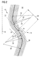
- Fig. 2 After the displacement of the blade root 12 is located at the Blade holder 14 at one shown in Fig. 2 Contact surface 20 on, the total of curved Surface sections is constructed.
- Fig. 2 shown Radial section show these curved surface sections on the blade root 12 and the blade holder 14 each as a convex surface portion 22 and immediately adjacent thereto arranged concave surface portion 24.
- the curved Surface sections 22 and 24 steer the one hand on the Blade acting forces towards the blade holder 14 towards (power flow line) and also transmit this Forces on the blade holder 14 (force transfer).
- the convex and concave surface portions 22 and 24 have each viewed in radial section constant and same Curvature radii 26 on. Between the surface portions 22 and 24 is a turning point 28, at which a tangent 30 to the contact surface 20 an angle of about 45 ° to Radial direction 16 takes up.
- the contact surface 20 is adjoined without transition (ie, C 1 continuous) surface regions whose radii of curvature 32 in the convex adjoining surface regions correspond to the radius of curvature 26 and whose radii of curvature 34 in the concave adjoining surface regions are slightly larger, so that at these subsequent surface regions at rated rotational speed the compressor between the blade root 12 and the blade holder 14 gives a slight play.
Landscapes
- Engineering & Computer Science (AREA)
- Mechanical Engineering (AREA)
- General Engineering & Computer Science (AREA)
- Structures Of Non-Positive Displacement Pumps (AREA)
Priority Applications (2)
| Application Number | Priority Date | Filing Date | Title |
|---|---|---|---|
| EP04008598A EP1584792A1 (fr) | 2004-04-08 | 2004-04-08 | Attachement d'aube pour un compresseur ou une turbine |
| PCT/EP2005/051473 WO2005098204A1 (fr) | 2004-04-08 | 2005-04-01 | Systeme de fixation de pale pour un compresseur ou une turbine |
Applications Claiming Priority (1)
| Application Number | Priority Date | Filing Date | Title |
|---|---|---|---|
| EP04008598A EP1584792A1 (fr) | 2004-04-08 | 2004-04-08 | Attachement d'aube pour un compresseur ou une turbine |
Publications (1)
| Publication Number | Publication Date |
|---|---|
| EP1584792A1 true EP1584792A1 (fr) | 2005-10-12 |
Family
ID=34896036
Family Applications (1)
| Application Number | Title | Priority Date | Filing Date |
|---|---|---|---|
| EP04008598A Withdrawn EP1584792A1 (fr) | 2004-04-08 | 2004-04-08 | Attachement d'aube pour un compresseur ou une turbine |
Country Status (2)
| Country | Link |
|---|---|
| EP (1) | EP1584792A1 (fr) |
| WO (1) | WO2005098204A1 (fr) |
Cited By (3)
| Publication number | Priority date | Publication date | Assignee | Title |
|---|---|---|---|---|
| EP1840337A1 (fr) * | 2006-03-31 | 2007-10-03 | Siemens Aktiengesellschaft | Joint de rainure et languette entre deux composants de turbine |
| EP2019913A4 (fr) * | 2006-05-12 | 2011-06-01 | Gen Electric | Contre-découpe en queue d'aronde de pale/disque pour une réduction de la contrainte pale/disque (6fa+e, étape 2) |
| EP2998516A1 (fr) * | 2014-09-18 | 2016-03-23 | Rolls-Royce plc | Moteur a turbine a gaz |
Citations (9)
| Publication number | Priority date | Publication date | Assignee | Title |
|---|---|---|---|---|
| US2255486A (en) * | 1938-10-01 | 1941-09-09 | Gen Electric | Elastic fluid turbine bucket wheel |
| DE734884C (de) * | 1940-10-13 | 1943-04-30 | Leonhard Reichert Dipl Ing | Turbinenlaufschaufel mit mehreren hintereinanderliegenden Haltezaehnen am Fuss |
| US4169694A (en) * | 1977-07-20 | 1979-10-02 | Electric Power Research Institute, Inc. | Ceramic rotor blade having root with double curvature |
| US4191509A (en) * | 1977-12-27 | 1980-03-04 | United Technologies Corporation | Rotor blade attachment |
| US4260331A (en) * | 1978-09-30 | 1981-04-07 | Rolls-Royce Limited | Root attachment for a gas turbine engine blade |
| US4692976A (en) * | 1985-07-30 | 1987-09-15 | Westinghouse Electric Corp. | Method of making scalable side entry turbine blade roots |
| EP0431766A1 (fr) * | 1989-11-30 | 1991-06-12 | ROLLS-ROYCE plc | Fixage amélioré d'une aube de turbine à gaz sur un disque de rotor de turbine |
| US5176500A (en) * | 1992-03-24 | 1993-01-05 | Westinghouse Electric Corp. | Two-lug side-entry turbine blade attachment |
| DE19705323A1 (de) * | 1997-02-12 | 1998-08-27 | Siemens Ag | Reduzierung von lokalen Spannungen in Schaufelfußnuten |
-
2004
- 2004-04-08 EP EP04008598A patent/EP1584792A1/fr not_active Withdrawn
-
2005
- 2005-04-01 WO PCT/EP2005/051473 patent/WO2005098204A1/fr not_active Ceased
Patent Citations (9)
| Publication number | Priority date | Publication date | Assignee | Title |
|---|---|---|---|---|
| US2255486A (en) * | 1938-10-01 | 1941-09-09 | Gen Electric | Elastic fluid turbine bucket wheel |
| DE734884C (de) * | 1940-10-13 | 1943-04-30 | Leonhard Reichert Dipl Ing | Turbinenlaufschaufel mit mehreren hintereinanderliegenden Haltezaehnen am Fuss |
| US4169694A (en) * | 1977-07-20 | 1979-10-02 | Electric Power Research Institute, Inc. | Ceramic rotor blade having root with double curvature |
| US4191509A (en) * | 1977-12-27 | 1980-03-04 | United Technologies Corporation | Rotor blade attachment |
| US4260331A (en) * | 1978-09-30 | 1981-04-07 | Rolls-Royce Limited | Root attachment for a gas turbine engine blade |
| US4692976A (en) * | 1985-07-30 | 1987-09-15 | Westinghouse Electric Corp. | Method of making scalable side entry turbine blade roots |
| EP0431766A1 (fr) * | 1989-11-30 | 1991-06-12 | ROLLS-ROYCE plc | Fixage amélioré d'une aube de turbine à gaz sur un disque de rotor de turbine |
| US5176500A (en) * | 1992-03-24 | 1993-01-05 | Westinghouse Electric Corp. | Two-lug side-entry turbine blade attachment |
| DE19705323A1 (de) * | 1997-02-12 | 1998-08-27 | Siemens Ag | Reduzierung von lokalen Spannungen in Schaufelfußnuten |
Cited By (4)
| Publication number | Priority date | Publication date | Assignee | Title |
|---|---|---|---|---|
| EP1840337A1 (fr) * | 2006-03-31 | 2007-10-03 | Siemens Aktiengesellschaft | Joint de rainure et languette entre deux composants de turbine |
| EP2019913A4 (fr) * | 2006-05-12 | 2011-06-01 | Gen Electric | Contre-découpe en queue d'aronde de pale/disque pour une réduction de la contrainte pale/disque (6fa+e, étape 2) |
| EP2998516A1 (fr) * | 2014-09-18 | 2016-03-23 | Rolls-Royce plc | Moteur a turbine a gaz |
| US9841031B2 (en) | 2014-09-18 | 2017-12-12 | Rolls-Royce Plc | Gas turbine engine |
Also Published As
| Publication number | Publication date |
|---|---|
| WO2005098204A1 (fr) | 2005-10-20 |
Similar Documents
| Publication | Publication Date | Title |
|---|---|---|
| DE69711793T2 (de) | Schaufel für axiale Strömungsmaschine | |
| DE69920358T2 (de) | Schaufelkonfiguration für Dampfturbinen | |
| EP3283733B1 (fr) | Dispositif d'actionnement des aubes de guidage variables et turbomachine | |
| DE2307967C2 (de) | Plattform für eine Verdichterschaufel | |
| DE69734560T2 (de) | Rotorschaufelpaar und Rotor mit einem solchen Schaufelpaar | |
| DE3223164C2 (de) | Turbomaschinenrotorbaugruppe und -laufschaufel | |
| EP1898054B1 (fr) | Turbine a gaz | |
| DE3527122A1 (de) | Schaufel und beschaufelte scheibenbaugruppe fuer ein gasturbinentriebwerk | |
| DE2622545A1 (de) | Stossabsorbierende einbauvorrichtung fuer steigungs- bzw. anstellungsvariable schaufeln | |
| CH703871B1 (de) | Verstellleitapparatanordnung für einen Verdichter. | |
| DE3618331A1 (de) | Betaetigungshebel fuer ein paar verstellbare leitschaufeln | |
| DE2704051A1 (de) | Plattform fuer schwingenden schaufelfuss | |
| EP1024081A2 (fr) | Moyeu pour pale d'hélices et de rotors | |
| DE10247767A1 (de) | Schaufel- und Radschwalbenschwanzausgestaltung für Turbinenrotoren | |
| CH705171A1 (de) | Turbinenschaufel mit einem Schaufelblatt aus Verbundwerkstoff und Verfahren zum Herstellen davon. | |
| EP3324002B1 (fr) | Système d'étanchéité pour une turbomachine et turbomachine axiale | |
| EP2297430A1 (fr) | Turbine axiale pour turbine à gaz, à faible jeu entre les aubes et la carcasse | |
| DE69929490T2 (de) | Gasturbine | |
| DE69728500T2 (de) | Turbomaschinenrotor | |
| WO2012016830A1 (fr) | Rotor de turbine à gaz à arbre de rotor de turbine mobile axialement | |
| DE2217085A1 (de) | Gegliederte huelse fuer turbinenlaschung | |
| EP2394028B1 (fr) | Dispositif d'étanchéité sur l'arbre à aubes d'un étage de rotor d'une turbomachine axiale et son utilisation | |
| CH647301A5 (de) | Laeuferrad einer turbine mit daran befestigten laufschaufeln. | |
| DE102004038639A1 (de) | Francis Turbine | |
| EP1584792A1 (fr) | Attachement d'aube pour un compresseur ou une turbine |
Legal Events
| Date | Code | Title | Description |
|---|---|---|---|
| PUAI | Public reference made under article 153(3) epc to a published international application that has entered the european phase |
Free format text: ORIGINAL CODE: 0009012 |
|
| AK | Designated contracting states |
Kind code of ref document: A1 Designated state(s): AT BE BG CH CY CZ DE DK EE ES FI FR GB GR HU IE IT LI LU MC NL PL PT RO SE SI SK TR |
|
| AX | Request for extension of the european patent |
Extension state: AL HR LT LV MK |
|
| 17P | Request for examination filed |
Effective date: 20051107 |
|
| AKX | Designation fees paid |
Designated state(s): CH DE GB IT LI |
|
| RAP1 | Party data changed (applicant data changed or rights of an application transferred) |
Owner name: SIEMENS AKTIENGESELLSCHAFT |
|
| RAP1 | Party data changed (applicant data changed or rights of an application transferred) |
Owner name: SIEMENS AKTIENGESELLSCHAFT |
|
| STAA | Information on the status of an ep patent application or granted ep patent |
Free format text: STATUS: THE APPLICATION IS DEEMED TO BE WITHDRAWN |
|
| 18D | Application deemed to be withdrawn |
Effective date: 20160607 |