EP1584792A1 - Blade attachment for a compressor or a turbine - Google Patents
Blade attachment for a compressor or a turbine Download PDFInfo
- Publication number
- EP1584792A1 EP1584792A1 EP04008598A EP04008598A EP1584792A1 EP 1584792 A1 EP1584792 A1 EP 1584792A1 EP 04008598 A EP04008598 A EP 04008598A EP 04008598 A EP04008598 A EP 04008598A EP 1584792 A1 EP1584792 A1 EP 1584792A1
- Authority
- EP
- European Patent Office
- Prior art keywords
- blade
- contact surface
- attachment according
- compressor
- holder
- Prior art date
- Legal status (The legal status is an assumption and is not a legal conclusion. Google has not performed a legal analysis and makes no representation as to the accuracy of the status listed.)
- Withdrawn
Links
- 238000006073 displacement reaction Methods 0.000 claims abstract description 5
- 239000000463 material Substances 0.000 description 4
- 239000011248 coating agent Substances 0.000 description 3
- 238000000576 coating method Methods 0.000 description 3
- 238000010276 construction Methods 0.000 description 3
- 230000009977 dual effect Effects 0.000 description 2
- 238000005299 abrasion Methods 0.000 description 1
- 238000005352 clarification Methods 0.000 description 1
- 230000000694 effects Effects 0.000 description 1
- 230000002349 favourable effect Effects 0.000 description 1
- 238000007493 shaping process Methods 0.000 description 1
- 230000007704 transition Effects 0.000 description 1
Images

Classifications
-
- F—MECHANICAL ENGINEERING; LIGHTING; HEATING; WEAPONS; BLASTING
- F01—MACHINES OR ENGINES IN GENERAL; ENGINE PLANTS IN GENERAL; STEAM ENGINES
- F01D—NON-POSITIVE DISPLACEMENT MACHINES OR ENGINES, e.g. STEAM TURBINES
- F01D5/00—Blades; Blade-carrying members; Heating, heat-insulating, cooling or antivibration means on the blades or the members
- F01D5/30—Fixing blades to rotors; Blade roots ; Blade spacers
- F01D5/3007—Fixing blades to rotors; Blade roots ; Blade spacers of axial insertion type
-
- F—MECHANICAL ENGINEERING; LIGHTING; HEATING; WEAPONS; BLASTING
- F05—INDEXING SCHEMES RELATING TO ENGINES OR PUMPS IN VARIOUS SUBCLASSES OF CLASSES F01-F04
- F05D—INDEXING SCHEME FOR ASPECTS RELATING TO NON-POSITIVE-DISPLACEMENT MACHINES OR ENGINES, GAS-TURBINES OR JET-PROPULSION PLANTS
- F05D2250/00—Geometry
- F05D2250/70—Shape
- F05D2250/71—Shape curved
- F05D2250/711—Shape curved convex
-
- F—MECHANICAL ENGINEERING; LIGHTING; HEATING; WEAPONS; BLASTING
- F05—INDEXING SCHEMES RELATING TO ENGINES OR PUMPS IN VARIOUS SUBCLASSES OF CLASSES F01-F04
- F05D—INDEXING SCHEME FOR ASPECTS RELATING TO NON-POSITIVE-DISPLACEMENT MACHINES OR ENGINES, GAS-TURBINES OR JET-PROPULSION PLANTS
- F05D2250/00—Geometry
- F05D2250/70—Shape
- F05D2250/71—Shape curved
- F05D2250/712—Shape curved concave
Definitions
- the invention relates to a blade attachment a Bucket for a compressor or a turbine, in which the Blade in operation of the compressor or turbine radial directed around a rotation axis, with a blade root, the on a blade holder opposite to the blade withholding forces.
- the invention is based on the object an input to provide said blade attachment, in which the Shovels on a blade holder with low Surface pressures and especially low Stress concentrations are maintained.
- the object is according to the invention with a generic Shovel attachment solved, at least one Contact area between the blade root and the Shovel holder is designed, which at standstill of the blade is at least partially subject to play and by a slight displacement of the blade root relative to Shovel holder during operation of the compressor or the Turbine due to the forces acting on the blade in transferred a play-free or reduced-play state is.
- the blade root and the Blade holder of the blade attachment according to the invention Wings provided at standstill of the associated Turbomachine game, but in operation of the Turbomachine, for example, if this at rated speed rotates, reduced or play-free.
- the invention based on the knowledge that the contact areas of blade and blade holder just then especially good solve the asked carrying task, if in its construction already the movement behavior of the associated blade due to acting on the blade centrifugal and Medium forces involved in the construction.
- This Movement behavior is considered according to the invention by the displacement of the blade root relative to the blade holder during operation of the compressor or turbine is determined due to the forces acting on the blade forces.
- Shovel foot and blade holder are then targeted to this Condition designed with play-free contact areas.
- Blade attachment is the contact area with a Designed contact surface, where the blade foot during the Operating the compressor or turbine on the blade holder abuts and the at least one radially curved Area section, i. one in a radial section (ie a cut that has a radius in its cutting plane contains) curved surface portion having.
- a such curved wing between the blade root and Shovel holder is particularly special tension-favorable power flow within the blade root implementable.
- one at least partially curved contact surface particularly then makes sense if both of the above subproblems of the Asked carrying task, namely both the power transfer as Also, the power flow line be equally optimally solved should.
- blade fasteners In known blade fasteners is the so-called force transfer area in which the on the blade acting forces from the blade root to the blade holder be transferred, and the so-called Power flow line area in which the on the blade acting forces from the longitudinal direction of the blade to Shovel holder to be deflected out, with two geometric addressed to separate functional elements.
- a blade attachment according to the invention which also without the in the characterizing part of claim 1 mentioned features can be designed, however, is at least one Sectionally curved contact surface provided in the the force transfer area and the power flow line area each other in a functional area of the blade root are designed overlapping. The curved surface section then transfers forces from the blade root to the blade holder and at the same time directs those out of the shovel inflowing forces in the direction of the blade holder.
- This dual function of sections of the contact surface can be used particularly meaningfully if the contact surface is aligned generally radially inclined and at least a radially curved surface portion at the axis of rotation facing edge region of the contact surface or on the of the Rotary axis weggewandten edge region of the contact surface is provided.
- the curved surface sections can be particularly advantageous be combined to a solution in which at the Blade attachment in a radial section looks at the Contact surface overall designed essentially S-shaped is.
- the contact surface can be in the center or its central area in a radial section considered a straight surface section or with a concave curved and immediately afterwards a convex curved Be provided surface section.
- the immediate consecutive curved sections carry both both for force transfer and for force diversion, so that no area section is left, the only Power transmits, but not diverts.
- the desired stress distribution in the material is such Solution particularly favorable.
- the force deflection within This solution can be done very evenly optimized surfaces based on splines used become.
- a particularly advantageous distribution of the voltages in the involved materials of blade root and blade holder, with nevertheless the required force deflection and the desired force transfer are possible, can be achieved by looking in a radial section of the radius of curvature the concave and / or convex curvature to the width of Contact area a ratio of about 5.0 to 4.0 to about 5.0 to 3.0, in particular from about 5.0 to 3.8.
- Blade attachment to the blade root and / or the blade holder at least one edge of the contact surface a curved Surface area be provided, the contact surface seamlessly connects.
- transitionless is here meant that between the contact surface and the arched area no edges or notches provided should be.
- Fig. 1 is a blade attachment 10 for fastening a blade root 12 of a further not illustrated Shovel shown on a blade holder 14 which on a rotor of a compressor arranged and in whose Running at high speed.
- the blade root 12 and the blade holder 14 are connected by a Groove-tooth connection or tongue and groove connection with each other in coupled to a contact area 18. From this groove-tooth connection is in Figs. 1 and 2 only one short Section with one groove and one tooth each illustrated. At the blade attachment 10 are between two and six such groove-tooth connections provided.
- Fig. 1 which shows the situation at standstill of Compressor shows, it can be seen that the forms of the Blade foot 12 and the blade holder 14 in the contact area 18 are designed so that between them in this Standstill situation game exists.
- This game is for Clarification of the solution according to the invention relatively shown big.
- the contact region 18 is furthermore shaped in such a way that that then sets a play-free state, if the Rotor of the compressor is in operation and with a Speed is near its rated speed.
- the shovel is due to the on her acting centrifugal forces as mentioned pulled radially outward and thereby also the blade root 12 relative to Blade holder 14 slightly shifted.
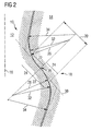
- Fig. 2 After the displacement of the blade root 12 is located at the Blade holder 14 at one shown in Fig. 2 Contact surface 20 on, the total of curved Surface sections is constructed.
- Fig. 2 shown Radial section show these curved surface sections on the blade root 12 and the blade holder 14 each as a convex surface portion 22 and immediately adjacent thereto arranged concave surface portion 24.
- the curved Surface sections 22 and 24 steer the one hand on the Blade acting forces towards the blade holder 14 towards (power flow line) and also transmit this Forces on the blade holder 14 (force transfer).
- the convex and concave surface portions 22 and 24 have each viewed in radial section constant and same Curvature radii 26 on. Between the surface portions 22 and 24 is a turning point 28, at which a tangent 30 to the contact surface 20 an angle of about 45 ° to Radial direction 16 takes up.
- the contact surface 20 is adjoined without transition (ie, C 1 continuous) surface regions whose radii of curvature 32 in the convex adjoining surface regions correspond to the radius of curvature 26 and whose radii of curvature 34 in the concave adjoining surface regions are slightly larger, so that at these subsequent surface regions at rated rotational speed the compressor between the blade root 12 and the blade holder 14 gives a slight play.
Landscapes
- Engineering & Computer Science (AREA)
- Mechanical Engineering (AREA)
- General Engineering & Computer Science (AREA)
- Structures Of Non-Positive Displacement Pumps (AREA)
Abstract
Description
Die Erfindung betrifft eine Schaufelbefestigung einer Schaufel für einen Verdichter oder eine Turbine, bei der die Schaufel im Betrieb des Verdichters oder der Turbine radial gerichtet um eine Drehachse umläuft, mit einem Schaufelfuß, der an einem Schaufelhalter entgegen der an der Schaufel wirkenden Kräfte zurückgehalten ist.The invention relates to a blade attachment a Bucket for a compressor or a turbine, in which the Blade in operation of the compressor or turbine radial directed around a rotation axis, with a blade root, the on a blade holder opposite to the blade withholding forces.
Bei Verdichtern oder Turbinen sind Schaufelräder mit Schaufeln vorgesehen, die mit hoher Drehzahl umlaufen und dabei hohen Fliehkräften ausgesetzt sind. Diese sogenannten Laufschaufeln müssen mit Hilfe von Schaufelbefestigungen sicher an einem Rotor des zugehörigen Verdichters bzw. der zugehörigen Turbine gehalten sein.In compressors or turbines are paddle wheels with Provided blades that rotate at high speed and are exposed to high centrifugal forces. These so-called Blades must with the help of blade fasteners safely on a rotor of the associated compressor or the associated turbine.
Als Schaufelbefestigungen sind aus US 5,169,289 A ein sogenannter Tannenfuß oder aus DE 100 14 189 A1 ein sogenannter Hammerfuß bekannt. Als weitere bekannte Lösungen von Schaufelfüßen werden sogenannte Reiterfüße oder Hakenfüße verwendet. Die Formgebung bekannter Schaufelfüße und zugehöriger Schaufelhalter führt jedoch zu Spannungskonzentrationen in den beteiligten Bauteilen, die ihrerseits eine Materialermüdung nach sich ziehen. Diese stellt eine absolute Beschränkung hinsichtlich der Größe der verwendbaren Schaufeln dar.As blade fasteners are from US 5,169,289 A a so-called Tannenfuß or from DE 100 14 189 A1 a so-called hammer foot known. As other known solutions Shovel feet become so-called equestrian feet or hooked feet used. The shape of known blade feet and However, associated blade holder leads to Stress concentrations in the involved components, the in turn cause material fatigue. These represents an absolute limitation on the size of the usable blades.
Als Teilproblem der Formgebung und Gestaltung von Schaufelbefestigungen an Laufschaufeln ist der Krafttransfer über Kontaktflächen zwischen Rotor und Schaufel zu lösen. Ein weiteres Teilproblem ist die Kraftflussleitung, d.h. das Umleiten der an der Schaufel wirkenden Kräfte hinein in den zugehörigen Schaufelhalter am Rotor, mit möglichst niedrigen Spannungskonzentrationen. As a subproblem of the shaping and design of Shovel mounts on blades is the power transfer To solve over contact surfaces between rotor and blade. One Another subproblem is the power flow line, i. the Divert the forces acting on the blade into the forces associated blade holder on the rotor, with the lowest possible Stress concentrations.
Der Erfindung liegt die Aufgabe zugrunde eine eingangs genannte Schaufelbefestigung bereitzustellen, bei der die Schaufeln an einem Schaufelhalter mit niedrigen Flächenpressungen und besonders geringen Spannungskonzentrationen gehalten sind.The invention is based on the object an input to provide said blade attachment, in which the Shovels on a blade holder with low Surface pressures and especially low Stress concentrations are maintained.
Die Aufgabe ist erfindungsgemäß mit einer gattungsgemäßen Schaufelbefestigung gelöst, bei der mindestens ein Kontaktbereich zwischen dem Schaufelfuß und dem Schaufelhalter gestaltet ist, der bei Stillstand der Schaufel mindestens teilweise spielbehaftet ist und durch ein geringfügiges Verschieben des Schaufelfußes relativ zum Schaufelhalter während des Betrieb des Verdichters oder der Turbine aufgrund der an der Schaufel wirkenden Kräfte in einen spielfreien oder spielreduzierten Zustand übergeführt ist.The object is according to the invention with a generic Shovel attachment solved, at least one Contact area between the blade root and the Shovel holder is designed, which at standstill of the blade is at least partially subject to play and by a slight displacement of the blade root relative to Shovel holder during operation of the compressor or the Turbine due to the forces acting on the blade in transferred a play-free or reduced-play state is.
Mit anderen Worten sind der Schaufelfuß und der Schaufelhalter der erfindungsgemäßen Schaufelbefestigung mit Tragflächen versehen, die bei Stillstand der zugehörigen Strömungsmaschine Spiel aufweisen, aber im Betrieb der Strömungsmaschine, beispielsweise wenn diese mit Nenndrehzahl umläuft, spielreduziert bzw. spielfrei sind. Die Erfindung basiert dabei auf der Erkenntnis, dass die Kontaktbereiche von Schaufelfuß und Schaufelhalter gerade dann besonders gut die gestellte Tragaufgabe lösen, wenn bei ihrer Konstruktion bereits das Bewegungsverhalten der zugehörigen Schaufel aufgrund der an der Schaufel wirkenden Flieh- und Mediumskräfte mit in die Konstruktion einbezogen wird. Dieses Bewegungsverhalten wird erfindungsgemäß berücksichtigt, indem die Verschiebung des Schaufelfußes relativ zum Schaufelhalter während des Betriebs des Verdichters oder der Turbine aufgrund der an der Schaufel wirkenden Kräfte ermittelt wird. Schaufelfuß und Schaufelhalter werden dann gezielt auf diesen Zustand hin mit spielfreien Kontaktbereichen konstruiert. Bei Stillstand bzw. verringerter Drehzahl des zugehörigen Verdichters oder der zugehörigen Turbine ist erfindungsgemäß die Konstruktion hingegen derart gestaltet, dass der Kontaktbereich zwischen Schaufelfuß und Schaufelhalter spielbehaftet ist. Eine solche spielbehaftete Situation führt zwar grundsätzlich zu erhöhten Flächenpressungen und erhöhten Spannungskonzentrationen, weil aber zugleich an der zugehörigen Schaufel geringere Kräfte wirken, sind die Flächenpressungen und Spannungskonzentrationen im Vergleich zur maximalen Belastung der Schaufelbefestigung gering.In other words, the blade root and the Blade holder of the blade attachment according to the invention Wings provided at standstill of the associated Turbomachine game, but in operation of the Turbomachine, for example, if this at rated speed rotates, reduced or play-free. The invention based on the knowledge that the contact areas of blade and blade holder just then especially good solve the asked carrying task, if in its construction already the movement behavior of the associated blade due to acting on the blade centrifugal and Medium forces involved in the construction. This Movement behavior is considered according to the invention by the displacement of the blade root relative to the blade holder during operation of the compressor or turbine is determined due to the forces acting on the blade forces. Shovel foot and blade holder are then targeted to this Condition designed with play-free contact areas. at Standstill or reduced speed of the associated Compressor or the associated turbine is according to the invention the construction, however, designed such that the Contact area between blade root and blade holder is subject to play. Such a game-afflicted situation leads Although basically to increased surface pressures and increased Stress concentrations, but because at the same time at the associated blade lower forces act, are the Surface pressures and stress concentrations in comparison low for maximum load on the blade attachment.
Insgesamt können mit der erfindungsgemäßen Schaufelbefestigung größere Tragaufgaben bewältigt oder vorhandene Tragaufgaben wirtschaftlicher gehandhabt werden.Overall, with the inventive Shovel attachment copes with larger carrying tasks or existing carrying tasks are handled more economically.
Damit an der erfindungsgemäßen Schaufelbefestigung die Gefahr von Reibverschleiß bzw. Fretting während des An- und Abfahrens des zugehörigen Verdichters oder der zugehörigen Turbine unterbunden ist, kann an dem Schaufelfuß und/oder dem Schaufelhalter insbesondere im Bereich der Tragflächen eine Beschichtung aufgebracht sein. Diese Beschichtung kann als abnutzende Schicht ausgelegt sein, welche durch Umformung oder Abrieb der Beschichtung zu einer selbsttätigen Entlastung gefährdeter Bereiche führt. Ein solches Vorgehen ist insbesondere sinnvoll, wenn Schaufelfuß und Schaufelhalter mit einer Materialpaarung gestaltet sind, die empfindlich gegen Reibverschleiß bzw. Fretting ist.So that at the blade attachment according to the invention the danger of fretting or fretting during on and off Shutdown of the associated compressor or the associated Turbine is prevented, can on the blade root and / or Bucket holder especially in the area of the wings Be applied coating. This coating can be used as Ablutzende layer to be designed, which by forming or abrasion of the coating to an automatic one Relieves endangered areas. Such an approach is particularly useful when blade foot and Shovel holder are designed with a material pairing, the is sensitive to fretting or fretting.
Bei einer vorteilhaften Weiterbildung der erfindungsgemäßen Schaufelbefestigung ist der Kontaktbereich mit einer Kontaktfläche gestaltet, an der der Schaufelfuß während des Betriebs des Verdichters oder der Turbine am Schaufelhalter anliegt und die mindestens einen radial gekrümmten Flächenabschnitt, d.h. einen in einem Radialschnitt (also einem Schnitt, der einen Radius in seiner Schnittebene enthält) gekrümmten Flächenabschnitt, aufweist. Mit einer derart gekrümmten Tragfläche zwischen Schaufelfuß und Schaufelhalter ist insbesondere ein besonders spannungsgünstiger Kraftfluss innerhalb des Schaufelfußes implementierbar. Darüber hinaus hat sich gezeigt, dass eine zumindest abschnittsweise gekrümmte Kontaktfläche besonders dann sinnvoll ist, wenn beide oben genannten Teilprobleme der gestellten Tragaufgabe, nämlich sowohl der Krafttransfer als auch die Kraftflussleitung gleichermaßen optimal gelöst sein sollen. Bei bekannten Schaufelbefestigungen ist der sogenannte Krafttransferbereich, in dem die an der Schaufel wirkenden Kräfte vom Schaufelfuß an den Schaufelhalter übertragen werden, und der sogenannte Kraftflussleitungsbereich, in dem die an der Schaufel wirkenden Kräfte aus der Längsrichtung der Schaufel zum Schaufelhalter hin umgelenkt werden, mit zwei geometrisch getrennten Funktionalelementen adressiert. Bei einer erfindungsgemäßen Schaufelbefestigung, welche auch ohne die im kennzeichnenden Teil des Anspruchs 1 genannten Merkmalen gestaltet sein kann, ist hingegen eine zumindest abschnittsweise gekrümmte Kontaktfläche vorgesehen, bei der der Krafttransferbereich und der Kraftflussleitungsbereich einander in einem Funktionsbereich des Schaufelfußes überlappend gestaltet sind. Der gekrümmte Flächenabschnitt überträgt dann Kräfte vom Schaufelfuß auf den Schaufelhalter und lenkt gleichzeitig bereits die aus der Schaufel einfließenden Kräfte in Richtung auf den Schaufelhalter um.In an advantageous embodiment of the invention Blade attachment is the contact area with a Designed contact surface, where the blade foot during the Operating the compressor or turbine on the blade holder abuts and the at least one radially curved Area section, i. one in a radial section (ie a cut that has a radius in its cutting plane contains) curved surface portion having. With a such curved wing between the blade root and Shovel holder is particularly special tension-favorable power flow within the blade root implementable. In addition, it has been shown that one at least partially curved contact surface particularly then makes sense if both of the above subproblems of the Asked carrying task, namely both the power transfer as Also, the power flow line be equally optimally solved should. In known blade fasteners is the so-called force transfer area in which the on the blade acting forces from the blade root to the blade holder be transferred, and the so-called Power flow line area in which the on the blade acting forces from the longitudinal direction of the blade to Shovel holder to be deflected out, with two geometric addressed to separate functional elements. At a blade attachment according to the invention, which also without the in the characterizing part of claim 1 mentioned features can be designed, however, is at least one Sectionally curved contact surface provided in the the force transfer area and the power flow line area each other in a functional area of the blade root are designed overlapping. The curved surface section then transfers forces from the blade root to the blade holder and at the same time directs those out of the shovel inflowing forces in the direction of the blade holder.
Diese Doppelfunktion von Abschnitten der Kontaktfläche kann besonders sinnvoll eingesetzt werden, wenn die Kontaktfläche insgesamt radial geneigt ausgerichtet ist und der mindestens eine radial gekrümmte Flächenabschnitt an dem zur Drehachse gewandten Randbereich der Kontaktfläche oder an dem von der Drehachse weggewandten Randbereich der Kontaktfläche vorgesehen ist.This dual function of sections of the contact surface can be used particularly meaningfully if the contact surface is aligned generally radially inclined and at least a radially curved surface portion at the axis of rotation facing edge region of the contact surface or on the of the Rotary axis weggewandten edge region of the contact surface is provided.
Die gekrümmten Flächenabschnitte können besonders vorteilhaft zu einer Lösung kombiniert werden, bei der an der Schaufelbefestigung in einem Radialschnitt betrachtet die Kontaktfläche insgesamt im Wesentlichen S-förmig gestaltet ist.The curved surface sections can be particularly advantageous be combined to a solution in which at the Blade attachment in a radial section looks at the Contact surface overall designed essentially S-shaped is.
Die Kontaktfläche kann im Zentrum bzw. ihrem Mittelbereich in einem Radialschnitt betrachtet einen geraden Flächenabschnitt aufweisen oder aber mit einem konkav gekrümmten und unmittelbar anschließend einem konvex gekrümmten Flächenabschnitt versehen sein. Die unmittelbar aufeinanderfolgenden gekrümmten Abschnitte tragen beide sowohl zum Krafttransfer als auch zur Kraftumlenkung bei, sodass kein Flächenabschnitt mehr vorhanden ist, der nur Kraft überträgt, nicht aber umlenkt. Hinsichtlich der angestrebten Spannungsverteilung im Material ist eine solche Lösung besonders günstig. Damit die Kraftumlenkung innerhalb dieser Lösung besonders gleichmäßig erfolgt, können optimierte Flächen auf der Basis von Splines verwendet werden.The contact surface can be in the center or its central area in a radial section considered a straight surface section or with a concave curved and immediately afterwards a convex curved Be provided surface section. The immediate consecutive curved sections carry both both for force transfer and for force diversion, so that no area section is left, the only Power transmits, but not diverts. With regard to the desired stress distribution in the material is such Solution particularly favorable. Thus the force deflection within This solution can be done very evenly optimized surfaces based on splines used become.
Eine besonders vorteilhafte Verteilung der Spannungen in dem beteiligten Materialien von Schaufelfuß und Schaufelhalter, mit der dennoch die geforderte Kraftumlenkung und der gewünschte Krafttransfer möglich sind, kann erzielt werden, indem in einem Radialschnitt betrachtet der Krümmungsradius der konkaven und/oder konvexen Krümmung zur Breite der Kontaktfläche ein Verhältnis von etwa 5,0 zu 4,0 bis etwa 5,0 zu 3,0, insbesondere von etwa 5,0 zu 3,8 einnimmt.A particularly advantageous distribution of the voltages in the involved materials of blade root and blade holder, with nevertheless the required force deflection and the desired force transfer are possible, can be achieved by looking in a radial section of the radius of curvature the concave and / or convex curvature to the width of Contact area a ratio of about 5.0 to 4.0 to about 5.0 to 3.0, in particular from about 5.0 to 3.8.
Hinsichtlich der angestrebten Doppelwirkung des erfindungsgemäßen Kontaktbereichs zum Krafttransfer und zur Kraftumlenkung sollte ferner in einem Radialschnitt betrachtet die Kontaktfläche zwischen einer bzw. der konkaven und einer bzw. der konvexen Krümmung einen Wendepunkt aufweisen, an dem eine Tangente an die Kontaktfläche zur Radialrichtung einen Winkel von zwischen etwa 35° und 55°, insbesondere von etwa 45° einnimmt. Eine solche radiale Neigung der Kontaktfläche hat sich hinsichtlich der gewünschten Doppelfunktion als besonders vorteilhaft gezeigt. With regard to the intended double effect of contact area according to the invention for power transfer and to Force redirection should also be in a radial cut considers the contact surface between one or the concave and one or the convex curvature a turning point at which a tangent to the contact surface for Radial direction an angle of between about 35 ° and 55 °, especially occupies about 45 °. Such a radial Inclination of the contact surface has been in terms of desired dual function shown to be particularly advantageous.
Schließlich sollte an der erfindungsgemäßen Schaufelbefestigung am Schaufelfuß und/oder am Schaufelhalter an mindestens einem Rand der Kontaktfläche ein gewölbter Flächenbereich vorgesehen sein, der an die Kontaktfläche übergangslos anschließt. Mit dem Begriff "übergangslos" ist hier gemeint, dass zwischen der Kontaktfläche und dem gewölbten Flächenbereich keine Kanten oder Kerben vorgesehen sein sollten.Finally, at the invention Blade attachment to the blade root and / or the blade holder at least one edge of the contact surface a curved Surface area be provided, the contact surface seamlessly connects. With the term "transitionless" is here meant that between the contact surface and the arched area no edges or notches provided should be.
Ferner ist es vorteilhaft, wenn in einem Radialschnitt betrachtet die Krümmungsradien der anschließenden gewölbten Flächenbereiche von Schaufelfuß und Schaufelhalter ein Verhältnis zwischen etwa 1,0 und 1,2, insbesondere etwa 1,1 aufweisen. Die erfindungsgemäß bei Nenndrehzahl geschaffene spielfreie Situation im Kontaktbereich zwischen Schaufelfuß und Schaufelhalter lässt sich bei derartigen Verhältnissen besonders vorteilhaft herstellen.Furthermore, it is advantageous if in a radial section considers the radii of curvature of the subsequent arched Surfaces of blade root and blade holder Ratio between about 1.0 and 1.2, especially about 1.1 exhibit. The inventively created at rated speed play-free situation in the contact area between blade root and blade holder can be in such conditions produce particularly advantageous.
Nachfolgend wir ein Ausführungsbeispiel einer erfindungsgemäßen Schaufelbefestigung anhand der beigefügten schematischen Zeichnungen näher erläutert. Es zeigt:
- Fig. 1
- einen Radialschnitt einer erfindungsgemäßen Schaufelbefestigung eines Verdichters bei dessen Stillstand und
- Fig. 2
- den Radialschnitt gemäß Fig. 1 bei Nenndrehzahl des Verdichters.
- Fig. 1
- a radial section of a blade attachment according to the invention of a compressor at its stoppage and
- Fig. 2
- the radial section of FIG. 1 at rated speed of the compressor.
In Fig. 1 ist eine Schaufelbefestigung 10 zum Befestigen
eines Schaufelfußes 12 einer weiter nicht veranschaulichten
Schaufel an einem Schaufelhalter 14 dargestellt, welcher an
einem Rotor eines Verdichters angeordnet und bei dessen
Betrieb mit hoher Drehzahl umläuft. In Fig. 1 is a
Bei der Rotation des Rotors mit seinem Schaufelhalter 14
läuft auch die genannte Schaufel, welche sich in einer
Radialrichtung 16 erstreckt mit um und unterliegt dabei hohen
Fliehkräften und Kräften aus dem Arbeitsmedium, welche die
Schaufel mit ihrem Schaufelfuß 12 radial nach außen, d.h.
bezogen auf Figur 1 nach oben ziehen, und tangential und
axial biegen. Bei Stillstand des Verdichters unterliegt die
Schaufel und deren Schaufelfuß 12 hingegen nicht diesen
Fliehkräften.During the rotation of the rotor with its
Der Schaufelfuß 12 und der Schaufelhalter 14 sind durch eine
Nut-Zahn-Verbindung bzw. Nut-Feder-Verbindung miteinander in
einem Kontaktbereich 18 gekoppelt. Von dieser Nut-Zahn-Verbindung
ist in den Fig. 1 und 2 nur jeweils ein kurzer
Abschnitt mit jeweils einer Nut und einem Zahn
veranschaulicht. An der Schaufelbefestigung 10 sind zwischen
zwei und sechs solcher Nut-Zahn-Verbindungen vorgesehen.The
In Fig. 1, welche die Situation bei Stillstand des
Verdichters zeigt, ist zu erkennen, dass die Formen des
Schaufelfußes 12 und des Schaufelhalters 14 im Kontaktbereich
18 derart gestaltet sind, dass zwischen ihnen in dieser
Stillstandssituation Spiel besteht. Dieses Spiel ist zur
Verdeutlichung der erfindungsgemäßen Lösung verhältnismäßig
groß dargestellt.In Fig. 1, which shows the situation at standstill of
Compressor shows, it can be seen that the forms of the
Zugleich ist der Kontaktbereich 18 ferner derart ausgeformt,
dass sich dann ein spielfreier Zustand einstellt, wenn der
Rotor des Verdichters im Betrieb ist und mit einer
Geschwindigkeit nahe seiner Nenndrehzahl umläuft. In einer
solchen Situation wird die Schaufel aufgrund der an ihr
wirkenden Fliehkräfte wie erwähnt radial nach außen gezogen
und dadurch auch der Schaufelfuß 12 relativ zum
Schaufelhalter 14 geringfügig verschoben.At the same time, the
Nach der Verschiebung liegt der Schaufelfuß 12 an dem
Schaufelhalter 14 an einer in Fig. 2 dargestellten
Kontaktfläche 20 an, die insgesamt aus gekrümmten
Flächenabschnitten aufgebaut ist. Im in Fig. 2 dargestellten
Radialschnitt zeigen sich diese gekrümmten Flächenabschnitte
am Schaufelfuß 12 und am Schaufelhalter 14 jeweils als ein
konvexer Flächenabschnitt 22 und ein unmittelbar daneben
angeordneter konkaver Flächenabschnitt 24. Die gekrümmten
Flächenabschnitte 22 und 24 lenken einerseits die an der
Schaufel wirkenden Kräfte in Richtung auf den Schaufelhalter
14 hin um (Kraftflussleitung) und übertragen ferner diese
Kräfte auf den Schaufelhalter 14 (Krafttransfer) .After the displacement of the
Die konvexen und konkaven Flächenabschnitte 22 und 24 weisen
jeweils im Radialschnitt betrachtet konstante und gleiche
Krümmungsradien 26 auf. Zwischen den Flächenabschnitten 22
und 24 befindet sich ein Wendepunkt 28, an dem eine Tangente
30 an die Kontaktfläche 20 einen Winkel von ca. 45° zur
Radialrichtung 16 hin einnimmt.The convex and
An die Kontaktfläche 20 schließen jeweils übergangslos (d.h.
C1-stetig) Flächenbereiche an, deren Krümmungsradien 32 in
den konvexen anschließenden Flächenbereichen dem
Krümmungsradius 26 entsprechen und deren Krümmungsradien 34
in den konkaven anschließenden Flächenbereichen geringfügig
größer sind, sodass sich an diesen anschließenden
Flächenbereichen bei Nenndrehzahl des Verdichters zwischen
dem Schaufelfuß 12 und dem Schaufelhalter 14 ein
geringfügiges Spiel ergibt.The
Claims (10)
dadurch gekennzeichnet, dass
mindestens ein Kontaktbereich (18) zwischen dem Schaufelfuß (12) und dem Schaufelhalter (14) gestaltet ist, der bei Stillstand der Schaufel spielbehaftet ist und durch ein geringfügiges Verschieben des Schaufelfußes (12) relativ zum Schaufelhalter (14) während des Betriebs des Verdichters oder der Turbine aufgrund der an der Schaufel wirkenden Kräfte in einen spielfreien oder spielreduzierten Zustand übergeführt ist.Blade attachment (10) of a blade for a compressor or a turbine, in which the blade rotates radially around an axis of rotation during operation of the compressor or the turbine, with a blade root (12) on a blade holder (14) opposite to the blade withholding forces,
characterized in that
at least one contact area (18) between the blade root (12) and the blade holder (14) is designed, which is at play standstill of the blade and by a slight displacement of the blade root (12) relative to the blade holder (14) during operation of the compressor or the turbine is converted into a play-free or reduced-play state due to the forces acting on the blade forces.
dadurch gekennzeichnet, dass
der Kontaktbereich (18) mit einer Kontaktfläche (20) gestaltet ist, an der der Schaufelfuß (12) während des Betriebs des Verdichters oder der Turbine am Schaufelhalter (14) anliegt und die mindestens einen radial gekrümmten Flächenabschnitt (22, 24) aufweist.Blade attachment according to claim 1,
characterized in that
the contact region (18) is designed with a contact surface (20) against which the blade root (12) bears against the blade holder (14) during operation of the compressor or turbine and which has at least one radially curved surface section (22, 24).
dadurch gekennzeichnet, dass
die Kontaktfläche (20) radial geneigt und der radial gekrümmte Flächenabschnitt (22, 24) an dem zur Drehachse gewandten Randbereich der Kontaktfläche (20) gestaltet ist. Blade attachment according to claim 2,
characterized in that
the contact surface (20) is inclined radially and the radially curved surface section (22, 24) is designed on the edge area of the contact surface (20) facing the axis of rotation.
dadurch gekennzeichnet, dass
die Kontaktfläche (20) radial geneigt und der radial gekrümmte Flächenabschnitt (22, 24) an dem von der Drehachse weggewandten Randbereich der Kontaktfläche (20) gestaltet ist.Blade attachment according to claim 2 or 3,
characterized in that
the contact surface (20) is inclined radially and the radially curved surface section (22, 24) is designed on the edge region of the contact surface (20) facing away from the axis of rotation.
dadurch gekennzeichnet, dass
in einem Radialschnitt betrachtet die Kontaktfläche (20) insgesamt im Wesentlichen S-förmig gestaltet ist.Blade attachment according to one of claims 1 to 4,
characterized in that
considered in a radial section, the contact surface (20) is designed to be substantially S-shaped overall.
dadurch gekennzeichnet, dass
in einem Radialschnitt betrachtet die Kontaktfläche (20) konkav und unmittelbar anschließend konvex gekrümmt, insbesondere auf der Basis von Splines, gekrümmt gestaltet ist.Blade attachment according to one of claims 1 to 5,
characterized in that
considered in a radial section, the contact surface (20) concave and immediately afterwards convexly curved, in particular on the basis of splines, is curved.
dadurch gekennzeichnet, dass
in einem Radialschnitt betrachtet der Krümmungsradius (26) der konkaven und/oder konvexen Krümmung zur Breite der Kontaktfläche (20) ein Verhältnis von etwa 5,0 zu 4,0 bis etwa 5,0 zu 3,0, insbesondere von etwa 5,0 zu 3,8 einnimmt.Blade attachment according to claim 6,
characterized in that
in a radial section, the radius of curvature (26) of the concave and / or convex curvature to the width of the contact surface (20), a ratio of about 5.0 to 4.0 to about 5.0 to 3.0, in particular of about 5.0 to 3.8.
dadurch gekennzeichnet, dass
in einem Radialschnitt betrachtet die Kontaktfläche (20) zwischen einer bzw. der konkaven und einer bzw. der konvexen Krümmung einen Wendepunkt (28) aufweist, an dem eine Tangente (30) an die Kontaktfläche (20) zur Radialrichtung (16) einen Winkel von zwischen etwa 35° und 55°, insbesondere von etwa 45° einnimmt. Blade attachment according to one of claims 1 to 7,
characterized in that
viewed in a radial section, the contact surface (20) between one or the concave and one or the convex curvature has a turning point (28) at which a tangent (30) to the contact surface (20) to the radial direction (16) at an angle of between about 35 ° and 55 °, in particular of about 45 ° occupies.
dadurch gekennzeichnet, dass
am Schaufelfuß (12) und/oder am Schaufelhalter (14) an mindestens einem Rand der Kontaktfläche (20) übergangslos ein gewölbter Flächenbereich anschließt.Blade attachment according to one of claims 1 to 8,
characterized in that
on the blade root (12) and / or on the blade holder (14) at at least one edge of the contact surface (20) seamlessly adjoining a curved surface region.
dadurch gekennzeichnet, dass
in einem Radialschnitt betrachtet die Krümmungsradien (32, 34) der anschließenden gewölbten Flächenbereiche von Schaufelfuß (12) und Schaufelhalter (14) ein Verhältnis zwischen etwa 1,0 und 1,2, insbesondere etwa 1,1 aufweisen.Blade attachment according to claim 9,
characterized in that
considered in a radial section, the radii of curvature (32, 34) of the subsequent curved surface areas of the blade root (12) and blade holder (14) have a ratio between about 1.0 and 1.2, in particular about 1.1.
Priority Applications (2)
| Application Number | Priority Date | Filing Date | Title |
|---|---|---|---|
| EP04008598A EP1584792A1 (en) | 2004-04-08 | 2004-04-08 | Blade attachment for a compressor or a turbine |
| PCT/EP2005/051473 WO2005098204A1 (en) | 2004-04-08 | 2005-04-01 | Blade fixing system for a compressor or a turbine |
Applications Claiming Priority (1)
| Application Number | Priority Date | Filing Date | Title |
|---|---|---|---|
| EP04008598A EP1584792A1 (en) | 2004-04-08 | 2004-04-08 | Blade attachment for a compressor or a turbine |
Publications (1)
| Publication Number | Publication Date |
|---|---|
| EP1584792A1 true EP1584792A1 (en) | 2005-10-12 |
Family
ID=34896036
Family Applications (1)
| Application Number | Title | Priority Date | Filing Date |
|---|---|---|---|
| EP04008598A Withdrawn EP1584792A1 (en) | 2004-04-08 | 2004-04-08 | Blade attachment for a compressor or a turbine |
Country Status (2)
| Country | Link |
|---|---|
| EP (1) | EP1584792A1 (en) |
| WO (1) | WO2005098204A1 (en) |
Cited By (3)
| Publication number | Priority date | Publication date | Assignee | Title |
|---|---|---|---|---|
| EP1840337A1 (en) * | 2006-03-31 | 2007-10-03 | Siemens Aktiengesellschaft | Tongue and groove connection between two components of a turbine |
| EP2019913A4 (en) * | 2006-05-12 | 2011-06-01 | Gen Electric | BLADE/DISK DOVETAIL BACKCUT FOR BLADE/DISK STRESS REDUCTION (6FA+e, STAGE 2) |
| EP2998516A1 (en) * | 2014-09-18 | 2016-03-23 | Rolls-Royce plc | Gas turbine engine |
Citations (9)
| Publication number | Priority date | Publication date | Assignee | Title |
|---|---|---|---|---|
| US2255486A (en) * | 1938-10-01 | 1941-09-09 | Gen Electric | Elastic fluid turbine bucket wheel |
| DE734884C (en) * | 1940-10-13 | 1943-04-30 | Leonhard Reichert Dipl Ing | Turbine blade with several holding teeth lying one behind the other at the foot |
| US4169694A (en) * | 1977-07-20 | 1979-10-02 | Electric Power Research Institute, Inc. | Ceramic rotor blade having root with double curvature |
| US4191509A (en) * | 1977-12-27 | 1980-03-04 | United Technologies Corporation | Rotor blade attachment |
| US4260331A (en) * | 1978-09-30 | 1981-04-07 | Rolls-Royce Limited | Root attachment for a gas turbine engine blade |
| US4692976A (en) * | 1985-07-30 | 1987-09-15 | Westinghouse Electric Corp. | Method of making scalable side entry turbine blade roots |
| EP0431766A1 (en) * | 1989-11-30 | 1991-06-12 | ROLLS-ROYCE plc | Improved attachment of a gas turbine engine blade to a turbine rotor disc |
| US5176500A (en) * | 1992-03-24 | 1993-01-05 | Westinghouse Electric Corp. | Two-lug side-entry turbine blade attachment |
| DE19705323A1 (en) * | 1997-02-12 | 1998-08-27 | Siemens Ag | Turbo-machine blade |
-
2004
- 2004-04-08 EP EP04008598A patent/EP1584792A1/en not_active Withdrawn
-
2005
- 2005-04-01 WO PCT/EP2005/051473 patent/WO2005098204A1/en not_active Ceased
Patent Citations (9)
| Publication number | Priority date | Publication date | Assignee | Title |
|---|---|---|---|---|
| US2255486A (en) * | 1938-10-01 | 1941-09-09 | Gen Electric | Elastic fluid turbine bucket wheel |
| DE734884C (en) * | 1940-10-13 | 1943-04-30 | Leonhard Reichert Dipl Ing | Turbine blade with several holding teeth lying one behind the other at the foot |
| US4169694A (en) * | 1977-07-20 | 1979-10-02 | Electric Power Research Institute, Inc. | Ceramic rotor blade having root with double curvature |
| US4191509A (en) * | 1977-12-27 | 1980-03-04 | United Technologies Corporation | Rotor blade attachment |
| US4260331A (en) * | 1978-09-30 | 1981-04-07 | Rolls-Royce Limited | Root attachment for a gas turbine engine blade |
| US4692976A (en) * | 1985-07-30 | 1987-09-15 | Westinghouse Electric Corp. | Method of making scalable side entry turbine blade roots |
| EP0431766A1 (en) * | 1989-11-30 | 1991-06-12 | ROLLS-ROYCE plc | Improved attachment of a gas turbine engine blade to a turbine rotor disc |
| US5176500A (en) * | 1992-03-24 | 1993-01-05 | Westinghouse Electric Corp. | Two-lug side-entry turbine blade attachment |
| DE19705323A1 (en) * | 1997-02-12 | 1998-08-27 | Siemens Ag | Turbo-machine blade |
Cited By (4)
| Publication number | Priority date | Publication date | Assignee | Title |
|---|---|---|---|---|
| EP1840337A1 (en) * | 2006-03-31 | 2007-10-03 | Siemens Aktiengesellschaft | Tongue and groove connection between two components of a turbine |
| EP2019913A4 (en) * | 2006-05-12 | 2011-06-01 | Gen Electric | BLADE/DISK DOVETAIL BACKCUT FOR BLADE/DISK STRESS REDUCTION (6FA+e, STAGE 2) |
| EP2998516A1 (en) * | 2014-09-18 | 2016-03-23 | Rolls-Royce plc | Gas turbine engine |
| US9841031B2 (en) | 2014-09-18 | 2017-12-12 | Rolls-Royce Plc | Gas turbine engine |
Also Published As
| Publication number | Publication date |
|---|---|
| WO2005098204A1 (en) | 2005-10-20 |
Similar Documents
| Publication | Publication Date | Title |
|---|---|---|
| DE69711793T2 (en) | Blade for axial fluid machine | |
| DE69920358T2 (en) | Bucket configuration for steam turbines | |
| EP3283733B1 (en) | Variable guide vane actuating device and turbomachine | |
| DE2307967C2 (en) | Platform for a compressor blade | |
| DE69734560T2 (en) | Rotor pair of rotors and rotor with such a pair of blades | |
| DE3223164C2 (en) | Turbo machine rotor assembly and blade | |
| EP1898054B1 (en) | Gas turbine | |
| DE3527122A1 (en) | SHOVEL AND BLADED DISC ASSEMBLY FOR A GAS TURBINE ENGINE | |
| DE2622545A1 (en) | SHOCK-ABSORBING INSTALLATION DEVICE FOR INCLINE OR VARIABLE EMPLOYMENT SHOVELS | |
| CH703871B1 (en) | Verstellleitapparatanordnung for a compressor. | |
| DE3618331A1 (en) | OPERATING LEVER FOR A PAIR OF ADJUSTABLE GUIDE BLADES | |
| DE2704051A1 (en) | PLATFORM FOR SWINGING SHOVEL FOOT | |
| EP1024081A2 (en) | Blade root for propellers and rotor blades | |
| DE10247767A1 (en) | Bucket and wheel dovetail joint for turbine rotor, has rotor wheel dovetail with hooks, with the slanted crushed surfaces of each hook pair define angles extending away from plane normal to the axis, angles being equal to one another | |
| CH705171A1 (en) | The turbine blade having an airfoil from composite material and method for manufacturing thereof. | |
| EP3324002B1 (en) | Sealing system for a turbomachine and axial flowmachine | |
| EP2297430A1 (en) | Axial turbine for a gas turbine with limited play between blades and housing | |
| DE69929490T2 (en) | gas turbine | |
| DE69728500T2 (en) | Turbomachinery rotor | |
| WO2012016830A1 (en) | Gas turbine rotor comprising an axially displaceable turbine rotor shaft | |
| DE2217085A1 (en) | JOINTED SLEEVE FOR TURBINE LASHING | |
| EP2394028B1 (en) | Sealing apparatus at the blade shaft of a rotor stage of an axial turbomachine and the use thereof | |
| CH647301A5 (en) | IMPELLER WHEEL OF A TURBINE WITH FASTENING BLADES. | |
| DE102004038639A1 (en) | Francis turbine for the generation of hydro-electricity has blade profile ratio minimizing trailing edge vortices | |
| EP1584792A1 (en) | Blade attachment for a compressor or a turbine |
Legal Events
| Date | Code | Title | Description |
|---|---|---|---|
| PUAI | Public reference made under article 153(3) epc to a published international application that has entered the european phase |
Free format text: ORIGINAL CODE: 0009012 |
|
| AK | Designated contracting states |
Kind code of ref document: A1 Designated state(s): AT BE BG CH CY CZ DE DK EE ES FI FR GB GR HU IE IT LI LU MC NL PL PT RO SE SI SK TR |
|
| AX | Request for extension of the european patent |
Extension state: AL HR LT LV MK |
|
| 17P | Request for examination filed |
Effective date: 20051107 |
|
| AKX | Designation fees paid |
Designated state(s): CH DE GB IT LI |
|
| RAP1 | Party data changed (applicant data changed or rights of an application transferred) |
Owner name: SIEMENS AKTIENGESELLSCHAFT |
|
| RAP1 | Party data changed (applicant data changed or rights of an application transferred) |
Owner name: SIEMENS AKTIENGESELLSCHAFT |
|
| STAA | Information on the status of an ep patent application or granted ep patent |
Free format text: STATUS: THE APPLICATION IS DEEMED TO BE WITHDRAWN |
|
| 18D | Application deemed to be withdrawn |
Effective date: 20160607 |