EP1584693A1 - Verfahren zur herstellung von metallischem eisen - Google Patents
Verfahren zur herstellung von metallischem eisen Download PDFInfo
- Publication number
- EP1584693A1 EP1584693A1 EP04702838A EP04702838A EP1584693A1 EP 1584693 A1 EP1584693 A1 EP 1584693A1 EP 04702838 A EP04702838 A EP 04702838A EP 04702838 A EP04702838 A EP 04702838A EP 1584693 A1 EP1584693 A1 EP 1584693A1
- Authority
- EP
- European Patent Office
- Prior art keywords
- hearth
- renewable
- metallic iron
- renewable hearth
- moving
- Prior art date
- Legal status (The legal status is an assumption and is not a legal conclusion. Google has not performed a legal analysis and makes no representation as to the accuracy of the status listed.)
- Granted
Links
Images


Classifications
-
- C—CHEMISTRY; METALLURGY
- C21—METALLURGY OF IRON
- C21B—MANUFACTURE OF IRON OR STEEL
- C21B13/00—Making spongy iron or liquid steel, by direct processes
- C21B13/008—Use of special additives or fluxing agents
-
- C—CHEMISTRY; METALLURGY
- C21—METALLURGY OF IRON
- C21B—MANUFACTURE OF IRON OR STEEL
- C21B13/00—Making spongy iron or liquid steel, by direct processes
- C21B13/10—Making spongy iron or liquid steel, by direct processes in hearth-type furnaces
-
- C—CHEMISTRY; METALLURGY
- C21—METALLURGY OF IRON
- C21B—MANUFACTURE OF IRON OR STEEL
- C21B13/00—Making spongy iron or liquid steel, by direct processes
- C21B13/0006—Making spongy iron or liquid steel, by direct processes obtaining iron or steel in a molten state
-
- C—CHEMISTRY; METALLURGY
- C21—METALLURGY OF IRON
- C21B—MANUFACTURE OF IRON OR STEEL
- C21B13/00—Making spongy iron or liquid steel, by direct processes
- C21B13/0066—Preliminary conditioning of the solid carbonaceous reductant
-
- C—CHEMISTRY; METALLURGY
- C21—METALLURGY OF IRON
- C21B—MANUFACTURE OF IRON OR STEEL
- C21B13/00—Making spongy iron or liquid steel, by direct processes
- C21B13/10—Making spongy iron or liquid steel, by direct processes in hearth-type furnaces
- C21B13/105—Rotary hearth-type furnaces
-
- C—CHEMISTRY; METALLURGY
- C22—METALLURGY; FERROUS OR NON-FERROUS ALLOYS; TREATMENT OF ALLOYS OR NON-FERROUS METALS
- C22B—PRODUCTION AND REFINING OF METALS; PRETREATMENT OF RAW MATERIALS
- C22B1/00—Preliminary treatment of ores or scrap
- C22B1/14—Agglomerating; Briquetting; Binding; Granulating
- C22B1/16—Sintering; Agglomerating
- C22B1/20—Sintering; Agglomerating in sintering machines with movable grates
-
- F—MECHANICAL ENGINEERING; LIGHTING; HEATING; WEAPONS; BLASTING
- F27—FURNACES; KILNS; OVENS; RETORTS
- F27B—FURNACES, KILNS, OVENS OR RETORTS IN GENERAL; OPEN SINTERING OR LIKE APPARATUS
- F27B9/00—Furnaces through which the charge is moved mechanically, e.g. of tunnel type; Similar furnaces in which the charge moves by gravity
- F27B9/14—Furnaces through which the charge is moved mechanically, e.g. of tunnel type; Similar furnaces in which the charge moves by gravity characterised by the path of the charge during treatment; characterised by the means by which the charge is moved during treatment
- F27B9/16—Furnaces through which the charge is moved mechanically, e.g. of tunnel type; Similar furnaces in which the charge moves by gravity characterised by the path of the charge during treatment; characterised by the means by which the charge is moved during treatment the charge moving in a circular or arcuate path
-
- F—MECHANICAL ENGINEERING; LIGHTING; HEATING; WEAPONS; BLASTING
- F27—FURNACES; KILNS; OVENS; RETORTS
- F27D—DETAILS OR ACCESSORIES OF FURNACES, KILNS, OVENS OR RETORTS, IN SO FAR AS THEY ARE OF KINDS OCCURRING IN MORE THAN ONE KIND OF FURNACE
- F27D1/00—Casings; Linings; Walls; Roofs
- F27D1/0003—Linings or walls
- F27D1/0006—Linings or walls formed from bricks or layers with a particular composition or specific characteristics
-
- C—CHEMISTRY; METALLURGY
- C22—METALLURGY; FERROUS OR NON-FERROUS ALLOYS; TREATMENT OF ALLOYS OR NON-FERROUS METALS
- C22B—PRODUCTION AND REFINING OF METALS; PRETREATMENT OF RAW MATERIALS
- C22B1/00—Preliminary treatment of ores or scrap
- C22B1/14—Agglomerating; Briquetting; Binding; Granulating
- C22B1/24—Binding; Briquetting ; Granulating
- C22B1/242—Binding; Briquetting ; Granulating with binders
- C22B1/244—Binding; Briquetting ; Granulating with binders organic
- C22B1/245—Binding; Briquetting ; Granulating with binders organic with carbonaceous material for the production of coked agglomerates
-
- Y—GENERAL TAGGING OF NEW TECHNOLOGICAL DEVELOPMENTS; GENERAL TAGGING OF CROSS-SECTIONAL TECHNOLOGIES SPANNING OVER SEVERAL SECTIONS OF THE IPC; TECHNICAL SUBJECTS COVERED BY FORMER USPC CROSS-REFERENCE ART COLLECTIONS [XRACs] AND DIGESTS
- Y02—TECHNOLOGIES OR APPLICATIONS FOR MITIGATION OR ADAPTATION AGAINST CLIMATE CHANGE
- Y02P—CLIMATE CHANGE MITIGATION TECHNOLOGIES IN THE PRODUCTION OR PROCESSING OF GOODS
- Y02P10/00—Technologies related to metal processing
- Y02P10/10—Reduction of greenhouse gas [GHG] emissions
- Y02P10/134—Reduction of greenhouse gas [GHG] emissions by avoiding CO2, e.g. using hydrogen
Definitions
- the present invention relates to methods for producing metallic iron, and more particularly, relates to an improved method for producing metallic iron.
- the metallic iron is produced by the steps of feeding a mixture, which contains a carbonaceous reductant such as coal and iron oxide such as iron ore, onto a moving hearth of a moving hearth reducing-melting furnace, then reducing and melting the iron oxide by heating, and subsequently cooling the metallic iron thus obtained for production, a continuous operation can be stably performed while damage done to the moving hearth is reduced as small as possible, or damaged surface portions of the hearth is repaired during operation.
- the mixture is composed of agglomerates in the form of pellets or the like, and the agglomerates as mentioned above are fed onto the hearth, powders are generated from the agglomerates by dropping impact or the like and is then deposited on the hearth. Since the powders thus deposited are heated and reduced together with the agglomerates, the deposited powders are formed into powdered reduced iron, and the agglomerates are formed into granular reduced iron.
- the granular reduced iron is discharged outside the furnace by a discharge screw; however, on the other hand, the powdered reduced iron is squeezed into the surface of the hearth.
- Patent No. 3075721 a technique that solves the problems described above.
- a hearth-forming material is fed into a furnace together with agglomerates, powders generated from the agglomerates are deposited on a surface of a hearth to form an iron oxide layer thereon, and in addition, a discharge device is intermittently or continuously moved in the direction toward the top of the furnace so that the operation is carried out while the gap between the discharge device and the iron oxide layer formed on the surface of the hearth is adjusted.
- powdered reduced iron is prevented from being squeezed into the surface of the hearth by the discharge device, the formation of plate-shaped reduced iron on the hearth is prevented thereby, and the deposited reduced iron powders are periodically scarped off; hence, a continuous operation can be carried out.
- the continuous operation can be carried out since the surface of the hearth is periodically renewed and repaired by scraping off the plate-shaped reduced iron formed on the surface of the hearth; however, the hearth itself is not scraped off.
- a production method in which after a mixture of iron oxide and a reductant is fed into a moving hearth reducing-melting furnace such as a rotary hearth furnace and is heated by radiant heat in the furnace while moving therethrough so that the iron oxide is reduced by the reductant, and subsequently, carburization, melting, aggregation, and slag separation are performed, granular solid metallic iron is discharged outside the furnace after cooling and solidification.
- a moving hearth reducing-melting furnace such as a rotary hearth furnace and is heated by radiant heat in the furnace while moving therethrough so that the iron oxide is reduced by the reductant, and subsequently, carburization, melting, aggregation, and slag separation are performed
- granular solid metallic iron is discharged outside the furnace after cooling and solidification.
- the inventors of the present invention has proposed a technique disclosed in Japanese Unexamined Patent Application Publication No.
- the present invention was made in consideration of the circumstances described above, and an object of the present invention is to provide a method for producing metallic iron, the method being suitable for performing a long continuous operation. According to the method described above, even when powdered metallic iron is squeezed into a surface of a hearth, or the hearth is damaged by slag infiltration and corrosion, the removal and repair can be easily performed, and the operation rate and maintenability of the hearth can be improved.
- a method for producing metallic iron which could solve the problems described above, according to the present invention is a method for producing metallic iron, in which after a mixture including a carbonaceous reducing agent and iron oxide is fed onto a moving hearth of a moving hearth reducing-melting furnace and is then heated so that the iron oxide is reduced and melted, metallic iron to be obtained is cooled and is then discharged outside the furnace for recovery.
- the method described above comprises, prior to the feed of the mixture, bedding a granular hearth material on the moving hearth for forming a layered renewable hearth which can be renewed; removing part or the entirety of the renewable hearth, which is degraded during operation, and newly feeding the hearth material for newly forming a renewable hearth; leveling the surface of the newly formed hearth; and subsequently feeding the mixture for producing the metallic iron.
- a method for producing metallic iron is a method for producing metallic iron, in which after a mixture including a carbonaceous reducing agent and iron oxide is fed onto a hearth of a moving hearth reducing-melting furnace and is then heated so that the iron oxide is reduced and melted, metallic iron to be obtained is cooled and is then discharged outside the furnace for recovery.
- the method described above comprises, prior to the feed of the mixture, bedding a hearth material on the hearth for forming a layered renewable hearth which can be renewed; feeding the hearth material on the surface of the renewable hearth which is degraded during operation so as to form a new surface of the hearth; leveling the newly formed surface of the hearth; and subsequently feeding the mixture for producing the metallic iron.
- the inventors of the present invention discovered a method comprising the steps of bedding a hearth material on a moving hearth for forming a renewable hearth which can be renewed; feeding an atmosphere-adjusting agent and a mixture of raw materials onto the renewable hearth for reducing and melting iron oxide; removing (or not removing) part or the entirety of the renewable hearth which is degraded during the operation; feeding a new hearth material for newly forming a renewable hearth; and subsequently feeding a mixture of raw materials for reducing and melting iron oxide.
- the degraded renewable hearth can be easily removed and repaired, and hence the operation rate and maintenability of the hearth can be improved as compared to those in the past.
- slag may be concentrated at part of the renewable hearth, or the mixture of raw materials thus fed may be unevenly heated in some cases, and hence improvement has been still required in terms of a long and stable operation.
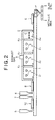
- Figs. 1 and 2 are schematic views for illustrating one example of a moving hearth reducing-melting furnace (rotary furnace), the furnace having a dome structure in which a doughnut-shaped rotary moving hearth is provided;
- Fig. 1 is a schematic plan view;
- Fig. 2 is a schematic cross-sectional view for illustrating the rotary moving hearth in Fig. 1 which is developed (after cutting a part indicated by the line A-A in Fig. 1) in the rotary moving direction in order to facilitate understanding of the furnace.
- Reference numeral 1 in the figure indicates a moving hearth
- reference numeral 2 indicates a furnace body covering the moving hearth
- the moving hearth 1 is formed to be driven at a desired speed by a drive device not shown in the figure.
- raw agglomerates agglomerates containing a carbonaceous reductant and iron oxide
- powder may also be used in the present invention.
- agglomerates various shapes such as pellets or briquettes may also be mentioned by way of example.
- the furnace body 2 is shown as a preferable example, and the inside of the furnace body 2 is divided into a reducing zone Z 1 to a cooling zone Z 4 by partitions K 1 to K 3 .
- raw agglomerate-feeding means 4, atmosphere-adjusting agent-feeding means 7, renewable hearth-leveling means 12, hearth material-feeding means 5, and raw material-leveling means 8 are disposed so as to oppose the moving hearth 1, and in addition, at the downstream side (since the rotary structure is formed, this side is actually positioned upstream with respect to the hearth material-feeding means 5 and just in front thereof) in the moving direction, a discharge device 6 is provided.
- a plurality of combustion burners 3 is provided, and by transmitting combustion heat of the combustion burners 3 and radiant heat thereof to the raw agglomerates provided on the moving hearth 1, heating and reduction of the raw agglomerates are carried out.
- the raw agglomerates are fed on the moving hearth 1 from the raw agglomerate-feeding means 4 so as to have an appropriate thickness.
- the raw agglomerates fed on the hearth 1 receives the combustion heat and radiant heat by the combustion burners 3 and are then reduced by carbon monoxide generated by the reaction between the iron oxide and the carbonaceous reducing agent, which are contained in the raw agglomerates, thereby forming reduced iron which is substantially thoroughly reduced.
- this reduced iron When being heated in a carbon-rich atmosphere, this reduced iron is carburized, melted, and aggregated while being separated from by-product slag to form granular molten metallic iron, and this molten metallic iron is then solidified by cooling in the cooling zone Z 4 using optional cooling means C and is sequentially discharged by the discharge device 6 positioned at the downstream side of the cooling zone Z 4 .
- the granular metallic iron is separated from the slag by optional separation means (sieves, magnetic separators, or the like) after passing through a hopper H, and as a result, granular metallic iron can be obtained having an iron purity of approximately 95% or more, and more preferably, having an iron purity of approximately 98% or more and containing a significantly small amount of slag component.
- optional separation means sieves, magnetic separators, or the like
- the present invention primarily focuses on the protection of the hearth forming the moving hearth 1 when highly pure metallic iron is produced in the moving hearth reducing-melting furnace described above, and hence, hereinafter, a method for repairing and renewing the hearth will be primarily described.
- the configuration of the moving hearth reducing-melting furnace to which the present invention is applied is not limited to the shape and the structure shown in Figs. 1 and 2, and as long as a moving type hearth is provided as a constituent element, the present invention may be effectively used for a moving hearth reducing-melting furnace having any structure such as a straight grate type.
- a production facility for producing metallic iron by the steps of feeding raw agglomerates, which contains iron oxide such as iron ore as an iron source and a carbonaceous reducing agent such as coal functioning as a reducing agent for the iron oxide, on the hearth of the moving hearth reducing-melting furnace followed by heating for reducing and melting the iron oxide, and discharging obtained metal iron outside the furnace after cooling, since the moving hearth 1 is protected which functions as a support layer when production of metallic iron is continuously performed by heating, reducing, carburizing, and melting, and the surface of the renewable hearth made of the hearth material is renewed, a stable operation can be carried out.
- the basic concept of the present invention is to produce metallic iron by the sequential steps of, prior to the feed of raw agglomerates, bedding a granular hearth material (hereinafter, simply referred to as "hearth material" in some cases) on a moving hearth for forming a layered renewable hearth; removing part or the entirety of the renewable hearth which is degraded during operation; newly feeding the hearth material for newly forming a renewable hearth; leveling the surface of the newly formed hearth; and subsequently feeding the mixture described above.
- a granular hearth material hereinafter, simply referred to as "hearth material” in some cases
- Figs. 3 and 4 are schematic cross-sectional views for illustrating one preferable embodiment of the present invention.
- a layered renewable hearth 9 which can be renewed, is formed by bedding the hearth material on the moving hearth 1 of the moving hearth reducing-melting furnace.
- the method for feeding the hearth material is not specifically limited; however, since being preferably bedded to have a uniform thickness on the moving hearth 1, it is recommended that, while the moving hearth 1 is moved at a predetermined speed, the hearth material in a predetermined amount be fed from the hearth material-feeding means 5 onto the moving hearth 1.
- the hearth is preferably rotated while the hearth material thus fed is leveled by the renewable hearth-leveling means 12 so that the renewable hearth layer has a predetermined thickness.
- the renewable hearth since the surface of the renewable hearth is compacted while being leveled by the renewable hearth-leveling means 12, a renewable hearth having appropriate strength and smoothness can be formed.
- the renewable hearth thus formed is a layer formed of granules right after the formation thereof; however, while being reduced and melted, the granules are bonded to each other and solidified so that part or the entirety of the renewable hearth may be discharged by the discharge device 6.
- the thickness of the renewable hearth is not particularly limited; however, in order to prevent refractories forming the moving hearth 1 from being damaged by molten slag, which infiltrates the renewable hearth and reaches the moving hearth 1, it is recommended that the thickness of the renewable hearth be preferably 5 mm or more, and more preferably, 10 mm or more.
- raw agglomerates G are fed onto the renewable hearth from the raw agglomerates-feeding means 4.
- the raw agglomerates G are adjusted so as to have a uniform thickness in the direction intersecting the moving direction of the renewable hearth by the raw material-leveling means 8.
- the raw material-leveling means 8 is means for smoothing overlapped raw agglomerates thus fed so as to be disposed uniformly in the width direction of the hearth, continuously in the moving direction thereof, and densely, and a known leveler may be used.
- the raw agglomerates G on the hearth may be moved in the width direction of the hearth by rotating a spiral blade 23 (23R, 23L).
- the structure of a particular raw material-leveling means is shown in Japanese Patent Application No. 11-243407.
- Metallic iron can be continuously produced by repeating the operation described above: however, with the operation time, the renewable hearth is degraded (degraded portion 9a of renewable hearth) by infiltration of the slag and molten iron, and hence stable metallic iron production cannot be continued. Examples of degradation of the renewable hearth are shown in Fig. 5.
- the moving hearth 1 may be damaged in some cases, and in this case, after the operation is stopped, the refractories forming the moving hearth 1 must be repaired.
- the granular metallic iron Fe and the slag Sg may be squeezed by the operation of the discharge device in some cases. In particular, they are likely to be squeezed into the hearth that is softened as described above.
- the slag Sg exposed to a high temperature is melted and further infiltrates the hearth.
- the renewable hearth with the metallic iron Fe squeezed therein is again moved through the reducing-melting zones, the metal Fe exposed to a high temperature is melted and may be overgrown in some cases by combination with other metallic iron squeezed into the renewable hearth or the metal Fe produced thereon.
- molten iron which cannot be sufficiently cooled and solidified by the cooling capability of the cooling zone, reaches the discharge device 6 and may not be discharged outside the furnace in some cases.
- fine metallic iron Fe and slag Sg which do not sufficiently aggregate and grow in the melting step, are likely to be squeezed into the renewable hearth.
- the metal Fe and slag Sg (for example, parts of the metal Fe and slag Sg project above the surface of the renewable hearth, and the rests thereof are squeezed therein) squeezed into the renewable hearth described above are removed by the discharge device 6, recesses are formed on the surface of the hearth.
- part of the renewable hearth is peeled off, thereby forming concave portions and convex portions on the surface of the renewable hearth.
- a large recess may be formed on the surface of the renewable hearth in some cases.
- convex portions are formed on the surface of the renewable hearth thereby (see Fig. 5).
- a front edge portion (contact portion in contact with materials to be discharged) of the discharge device 6 is damaged, such as wear or chipping, by discharge operation, such as discharge of the granular metal Fe, or scraping of the renewable hearth.
- discharge operation such as discharge of the granular metal Fe, or scraping of the renewable hearth.
- the granular metal Fe and slag Sg present on the renewable hearth cannot not be discharged, and parts of the granular metal Fe and slag Sg may be squeezed therein, thereby forming convex portions on the surface of the renewable hearth in some cases.
- the raw agglomerates thus fed may be unevenly heated because of the presence of the concave and convex portions, the metallic iron or the slag may be accumulated in the concave portions so that the metallic iron is overgrown, or as a result, melting thereof may be facilitated thereby.
- the concave and convex portions are formed as described above, the thickness of the raw agglomerates cannot be made uniform by the raw material-leveling means 8 (Fig. 10). In the operation described above, the production efficiency of the metallic iron is decreased.
- the renewal of the renewable hearth of the present invention restores the functions of the renewable hearth that were degraded as described above so that the stable metallic iron production can be continued, and examples of renewing methods are shown in Figs. 6 to 9.
- the front edge portion of the discharge device is disposed in the vicinity of the surface of the degraded portion 9a of the renewable hearth and discharges metallic iron Fe (15 in the figure) and slag Sg present on the degraded portion 9a of the renewable hearth outside the furnace (in this case, the degraded portion 9a of the renewable hearth is not scraped off).
- an overgrown material (16) which is formed of the metal Fe on the surface of the degraded portion of the renewable hearth combined with the metal Fe squeezed therein, may be caught by the front edge portion of a blade of the discharge device 6 and may then be discharged in some cases.
- a degraded renewable hearth may be removed by the discharge device 6, that is, may be peeled off from the surface of the renewable hearth in some cases.
- a concave portion 16a is formed on the surface of the renewable hearth.
- the slag Sg (17) having a part projecting above the surface of the degraded portion 9a of the renewable hearth cannot be substantially squeezed therein by the discharge device 6, a convex portion 17a is formed on the surface of the degraded portion 9a of the renewable hearth.
- the front edge portion of the blade of the discharge device 6 is damaged as described above, concave and convex portions are likely to be formed on the surface of the degraded portion.
- the degraded portion 9a of the renewable hearth is renewed by feeding the hearth material onto the degraded portion 9a of the renewable hearth from the hearth material-feeding means 5.
- the thickness of a layer of a new renewable hearth provided on the degraded portion of the renewable hearth is not particularly limited, the feed amount of the hearth material may be optionally changed in accordance with the degree of degradation of the hearth, and for example, a hearth material Hm may be fed so as to have a thickness of 2 mm or more.
- the hearth material Hm may be fed only to the concave portion 16a from the hearth material-feeding means 15.
- accurate control is required, and in addition, it is difficult to ideally smooth the concave portion only by feeding the hearth material Hm.
- the renewable hearth-leveling means 12 (16c, 17c).
- FIG. 9 Reference numeral 20 in Figs. 9(A) and (B) indicates the same portion, (A) is a view showing the state prior to the leveling operation, and (B) is a view showing the state after the leveling operation.
- the renewable hearth-leveling means 12 is not particularly limited as long as having a leveling function of leveling the surface of the renewable hearth, and for example, a series of plates disposed in an intersecting direction may be used, or the same device as the discharge device 6 may also be used.
- the particular structure is disclosed, for example, in USP 6,251,161.
- the discharge device disclosed in USP 6,251,161 is used as the renewable hearth-leveling means 12. This device moves the fed hearth material in the direction intersecting the moving direction of the renewable hearth so as to fill the concave portions thereon.
- a concave and a convex portion shown in Fig. 9(A) are the concave and convex portions (16b, 17b) remaining on the surface of the newly formed renewable hearth.
- the front edge portion of the blade of the renewable hearth-leveling means 12 is disposed at an optional depth in the hearth material Hm, the hearth material present at the upper side of the front edge portion of the blade is blocked at a front edge portion 12b of the blade and is mounded as an excessive hearth material Hm in the vicinity of the renewable hearth-leveling means 12, and hence when being moved in the vicinity of the front edge 12b of the blade, the concave portion 16b is filled with the excessive hearth material Hm (16c).
- the surface of the renewable hearth can be smoothed by the renewable hearth-leveling means 12 (B).
- the front edge portion of the blade of the renewable hearth-leveling means 12 may be made of a flexible material, the width 12a of the front edge portion of the blade may be decreased, or the depth thereof may be adjusted to be shallower.
- the front edge portion of the blade of the renewable hearth-leveling means 12 may has a tilt angle of 90° or more at the entry side, the width 12a of the front edge of the blade may be increased, or the position thereof in the vertical direction may be adjusted to be deeper.
- the discharge device disclosed in USP 6,251,161 is used as the renewable hearth-leveling means 12, it is preferable since the renewable hearth can be compacted when being leveled.
- the renewable hearth when the raw agglomerates G are fed onto the renewable hearth, the renewable hearth may be compacted by the weight of the raw agglomerates to form recesses in some cases, so that the smoothness of the surface of the renewable hearth may be lost. Accordingly, the renewable hearth is preferably compacted by the renewable hearth-leveling means 12 as described above.
- the thickness of the renewable hearth can be controlled.
- the fron edge portion of the blade of the discharge device 6 is located slightly above the degraded portion 9a of the renewable hearth, when the hearth material is newly fed, a new layer of the renewable hearth is formed on the degraded portion of the renewable hearth, thereby restoring the functions of the renewable hearth.
- the discharge device 6 since the thickness of the renewable hearth itself is increased, in accordance with the thickness thereof, the discharge device 6, the renewable hearth-leveling means 12, or the like may be raised so that the position of each front edge portion is adjusted.
- part or the entirety of the renewable hearth may be removed by lowering the discharge device 6 as shown in Figs. 7 and 8.
- a renewable hearth having a layered structure which can be renewed, is formed by bedding the granular hearth material on the moving hearth 1 as described above, part of the renewable hearth which is degraded during the operation is removed, the hearth material is newly fed to newly form a renewable hearth, and the surface of the newly formed renewable hearth is leveled. Subsequently, the raw agglomerates are fed, thereby producing metallic iron.
- the front edge portion of the blade of the discharge device 6 is set at an optional position of the degraded portion of the renewable hearth so that the part of the degraded portion of the renewable hearth (upper side of the front edge portion of the blade of the discharge device) is discharged together with the metallic iron Fe (15).
- the part of the degraded portion of the renewable hearth upper side of the front edge portion of the blade of the discharge device
- the metallic iron Fe metallic iron Fe
- the surface of the newly formed renewable hearth can be leveled by the renewable hearth-leveling means 12 (the particular operation of the renewable hearth-leveling means 12 is equivalent to that shown in Figs. 6 and 9) .
- a renewable hearth having a layered structure which can be renewed, is formed by bedding the granular hearth material on the moving hearth 1 as described above, the entirety of the renewable hearth which is degraded during the operation is removed, a new hearth material is then fed to newly form a renewable hearth, and the surface of the newly formed hearth is leveled. Subsequently, the raw agglomerates are fed, thereby producing metallic iron. Accordingly, the front edge portion of the blade of the discharge device 6 is set at an optional position under the degraded portion of the renewable hearth, and the degraded portion of the renewable hearth is discharged together with the metallic iron Fe (15). In addition, concomitant with the discharge described above, the slag 17, metallic iron (not shown), and the like present in the degraded portion of the renewable hearth are simultaneously discharged.
- the convex portion 17a and the concave portion 16a may be formed at the degraded portion of the renewable hearth in some cases depending on the position of the blade of the discharge device; however, in the case described above, the newly formed surface of the renewable hearth may be leveled by the renewable hearth-leveling means 12 (the particular operation of the renewable hearth-leveling means 12 is equivalent to that shown in Figs. 6 and 9).
- the blade of the discharge device when the blade of the discharge device is disposed at a deeper position, concaves and convexes caused by metallic iron Fe (16) and the slag Sg (17) may not be formed in some cases on the newly exposed surface of the renewable hearth.
- the inside of the furnace is maintained at a high temperature, when the hearth material Hm is fed onto the hearth, by upward blowing of gases in the furnace or the like, the hearth material may not be fed evenly onto the hearth, and hence concaves and convexes may be formed on the newly formed surface of the renewable hearth in some cases.
- the newly formed surface of the renewable hearth is preferably leveled by the renewable hearth-leveling means 12 as described above.
- the feed amount of the hearth material may be increased so as to have a given thickness.
- the particular structure of the discharge device 6 of the present invention is not specifically limited, and optional removing means (not shown) may be used.
- optional removing means may be used.
- a scraper type or a screw type may be used.
- a method for moving the discharge device 6, renewable hearth-leveling means 12, raw material-leveling means 8, or the like in the vertical direction is not specifically limited, and a jack, a hydraulic or air cylinder, or the like may be used for control.
- the degraded portion 9a of the renewable hearth may be removed.
- the structures shown in Figs. 6 to 9 described above may be optionally combined with each other for performing the operation.
- the operation is continued while the hearth material is fed thereon, and when the renewable hearth reaches a predetermined height, or when a predetermined time passes, part or the entirety of the renewable hearth may be removed by the discharge device 6 as shown in Figs. 7 and 8.
- the height of the renewable hearth may be lowered in some cases; however, in the case described above, when the height of the renewable hearth is lowered to a predetermined position, the feed amount of the hearth material may be increased so that the height of the renewable hearth again has the initial set value. In addition, whenever the degraded portion of the renewable hearth is removed, the hearth material may be newly fed so that thickness of the renewable hearth again has a predetermined value.
- the front edge portion of the blade of the discharge device 6 may be set in the vicinity of the moving hearth 1 so as to remove almost the entire amount of the renewable hearth every time, the hearth material may be fed from the hearth material-feeding means 5 so as to form the renewable hearth, and the raw agglomerates may be fed after the surface of the renewable hearth is leveled (preferably compacted in this step) by the renewable hearth-leveling means 12; however, in the case described above, since the consumption of the hearth material is increased, the operation cost is increased.
- a powdered carbonaceous material may be used, and as the carbonaceous material, for example, there may be mentioned coal (hard coal, bituminous coal, sub-bituminous coal, brown coal, or the like), reformed coal, petrocoke, or coke breeze.
- coal hard coal, bituminous coal, sub-bituminous coal, brown coal, or the like
- reformed coal petrocoke, or coke breeze.
- a high melting point material having corrosion resistance against molten slag may be used as the hearth material.
- an oxide containing alumina or magnesia or a material containing silicon carbide may be mentioned by way of example; however, another material having properties similar to those described above may also be used.
- the hearth materials as described above may be used alone or in combination.
- the renewable hearth is formed of a hearth material that contains a high melting point material having superior corrosion resistance as described above, the degradation of the renewable hearth caused by corrosion by the molten slag can be slowed, the consumption of the hearth material can be reduced, and as a result, the operation rate of facility can be increased.
- the hearth material is a hearth material containing a high melting point material having corrosion resistance and a carbonaceous material
- the carbonaceous material is consumed by combustion during carburizing and melting, and in addition, the renewable hearth is sintered to form the porous structure having an appropriate strength.
- the porous structure described above is formed, since the degradation and expansion of the renewable hearth can be suppressed, the formation of relatively large recesses formed by removal of the degraded and expanded portion can be prevented.
- the renewable hearth has the porous structure, it is preferable since the discharge of the renewable hearth can be easily performed by the discharge device 6, and the damage to the front edge portion of the blade of the discharge device 6 can be reduced.
- coal is used as the carbonaceous material.
- the reason for this is that since ash in the coal effectively serve as a binder for binding the particles of the hearth material (high melting point material) to each other, the renewable hearth becomes to have an appropriate strength when the raw agglomerates are fed, or the metallic iron product and the slag Sg are discharged.
- a composition ratio having a desired binder effect may be selected.
- the composition ratio of the high melting point material to the carbonaceous material is not specifically limited; however, when the amount of the carbonaceous material is small, since the renewable hearth cannot be satisfactorily formed so as to have pores therein, the effect of suppressing degradation and expansion caused by infiltration of molten slag and the easiness of removing the degraded portion 9a of the renewable hearth are decreased. On the other hand, when the amount of the carbonaceous material is excessive, since a predetermined strength of the renewable hearth cannot be obtained, recesses may be formed thereon by the weight of the raw agglomerates G, or infiltration of the molten slag is likely to occur.
- the ratio of the high melting point material to the carbonaceous material be preferably in the range of from 20 to 80 to 80 to 20, and more preferably, from 70 to 30 to 30 to 70.
- a material such as limestone or dolomite, which is to be used as a CaO source or an MgO source, may be mixed with the hearth material or may be supplied onto the surfaces of the raw agglomerates G.
- the hearth material may contain a sintering promoter.
- a sintering promoter When the sintering promoter is blended in the hearth material, it is preferable since the binder effect described above of binding particles of the high melting point material to each other can be obtained.
- a silica compound such as kaolin may be mentioned by way of example: however, as long as having the effect as a binder, another material may also be used.
- the composition ratio of the sintering promoter is not specifically limited as long as having the binder effect, and in general the content thereof is approximately 3 to 15%. Since the silica compound mentioned above as the sintering promoter by way of example has inferior corrosion resistance against molten slag, a large amount of the silica compound is not preferably blended in the hearth material.
- the particle diameters of the high melting point material, carbonaceous material, and sintering promoter, which are contained in the hearth material are not specifically limited; however, in order to suppresses the infiltration of the molten slag and to maintain the well-balanced relationship between the strength, which can withstand the operations of the feed of the raw agglomerates and the discharge of the metallic iron product and slag, and the easiness of removing the degraded portion of the renewable hearth, it is recommended that the average particle diameter be preferably 4 mm or less, and more preferably, 2 mm or less.
- an atmosphere-adjusting agent 10 containing a powdered carbonaceous material is bedded on the renewable hearth 9 so as to form a layered structure, and the raw agglomerates may then be fed thereon.
- the atmosphere-adjusting agent 10 By feeding the atmosphere-adjusting agent 10 from the atmosphere-adjusting agent-feeding means 7, while degradation of a reducing atmosphere in the vicinity of the raw agglomerates G, which is caused by an oxidizing burner-combustion gas containing CO 2 or H 2 O, is suppressed, reduction, carburization, and melting of the raw agglomerates G can be efficiently performed, and in addition, since the amount of FeO remaining in the molten slag is reduced, the infiltration into the renewable hearth and the corrosion thereof can be suppressed. Furthermore, since being burned in the furnace after the reducing atmosphere in the vicinity of the raw agglomerates G is enhanced, the atmosphere-adjusting agent also serves as a fuel, and hence the consumption of burner fuel such as a natural gas can be reduced.
- the atmosphere-adjusting agent allows the metallic iron Fe and the slag Sg to be easily separated from the renewable hearth, and hence the discharge thereof outside the furnace can be more smoothly performed.
- the atmosphere-adjusting agent described above for example, there may be mentioned powdered coal (hard coal, bituminous coal, sub-bituminous coal, brown coal, or the like), powdered reformed coal, powdered petrocoke, or coke breeze.
- the thickness of the atmosphere-adjusting agent is not specifically limited; however, in order to efficiently obtain the effect of enhancing the reducing atmosphere in the vicinity of the raw agglomerates or the effect of smoothly discharging the metallic iron and slag, a significantly small thickness may work well, and in general, the object can be satisfactorily achieved even when the thickness is approximately 1 to 10 mm. In addition, since being consumed in the furnace by combustion, it is preferable that the atmosphere-adjusting agent be continuously fed.
- the average particle diameter of the atmosphere-adjusting agent is not specifically limited; however, it is recommended that the average particle diameter be preferably 5 mm or less, and more preferably, 2 mm or less.
- a material such as limestone or dolomite which is to be used as a CaO source or an MgO source, may be mixed with the atmosphere-adjusting agent.
- the hearth material blended in the atmosphere-adjusting agent is moved to the discharge device 6 by the rotation of the hearth and is squeezed into the surface layer of the renewable hearth by the discharge device, thereby restoring the functions of the renewable hearth.
- the composition ratio of the hearth material to the atmosphere-adjusting agent is preferably 30 to 70%.
- Blending of the hearth material in the atmosphere-adjusting agent is not always necessary and may be performed only when the functions of the degraded portion of the renewable hearth are restored. Furthermore, according to the method described above, the hearth material and the atmosphere-adjusting agent can be fed by one common feeding device, and hence it is preferable since the facility cost and the installation space can be reduced.
- the atmosphere-adjusting agent containing a powdered carbonaceous material may be fed onto the renewable hearth 9 by the atmosphere-adjusting agent-feeding means.
- the feeding position is not specifically limited, and the atmosphere-adjusting agent may be fed simultaneously with the raw agglomerates or before the feed thereof from a position different from that at which the raw agglomerates is fed. Since the lower edge of the blade of the discharge device 6 is always in contact with the surface of the renewable hearth formed of the hearth material containing high melting point material, such as alumina or magnesia, which have high abrasive properties, the blade is considerably abraded.
- the atmosphere-adjusting agent by feeding the atmosphere-adjusting agent to form a thick layer thereof, since part of the atmosphere-adjusting agent remains (thin film) in the discharge step after reducing and melting, when the front edge portion of the blade is brought into contact with the atmosphere-adjusting agent layer, the life of the blade can be increased as compared to that obtained in the case in which the renewable hearth is directly removed, thereby increasing the operation rate of the facility.
- the feed thereof may be performed from the atmosphere-adjusting agent-feeding means 7; however, depending on the moving speed of the hearth, the amount of the atmosphere-adjusting agent, which is sufficient to obtain the effect described above, may not be fed once, and hence the feed thereof is preferably performed in twice.
- the composition of the atmosphere-adjusting agent for the first feed and that for the second feed may be or may not be different from each other.
- the positions at which the atmosphere-adjusting agent is fed are not specifically limited, and the atmosphere-adjusting agent may be fed simultaneously with the raw agglomerates or before or after the feed thereof from a position different from that at which the raw agglomerates is fed.
- the molten iron may be cooled and solidified.
- a water spray device so as to supply water to the molten iron portion, the molten iron may be cooled and solidified.
- a method for softening the renewable hearth is not specifically limited, and for example, there may be mentioned a method in which the burner combustion amount is increased to increase a furnace temperature so that a temperature of the renewable hearth is increased for softening; or a method in which a burner is installed which is exclusively used for direct heating of the renewable hearth so that a temperature thereof is increased for softening.
- the temperature of the renewable hearth in this step is not specifically limited and may be optionally set in accordance with the properties of the renewable hearth. However, at the degraded portion of the renewable hearth in which the infiltration of the slag proceeds, the temperature is preferably in the range of 1,300 to 1,550, and more preferably, in the range of 1,450 to 1,550°C.
- softening may be performed by supplying to the renewable hearth an additive having the effect of decreasing the melting point of the renewable hearth.
- an additive having the effect of decreasing the melting point of the renewable hearth.
- the additive described above for example, there may be mentioned calcium oxide, sodium oxide, sodium carbonate, or calcium fluoride.
- a carbon material such as a powdered carbonaceous material is bedded to form a layered carbonaceous layer, and removal may be performed by lowering the front edge portion of the blade of the discharge device to an optional position of the carbonaceous layer. Since the carbonaceous layer maintains the powder properties, the renewable hearth provided on the layer described above can be easily removed therefrom.
- the operation rate of the hearth can be significantly increased, and hence long and stable production of metallic iron can be achieved.
- the raw agglomerates in the form of pellets are described as the mixture of raw materials; however, when powder is used as the mixture of raw materials, the advantages of the present invention described above can also be obtained.
- Metallic iron is produced by feeding agglomerates (a diameter of approximately 16 mm) containing iron ore and coal into a moving hearth reducing-melting furnace shown in Fig. 1. After solid reduction is performed by controlling the furnace-atmosphere temperature at approximately 1,350°C until the metallization rate reaches approximately 90% or more, and melting is then preformed in a melting zone (an atmospheric temperature of 1,450°C), the metallic iron thus produced and by-product slag are cooled to approximately 1,000°C for solidification and are then discharged outside the furnace by the discharge device (approximately 12 minutes from the feed of the raw materials to the discharge thereof).
- the granular metallic iron (a diameter of approximately 10 mm) thus obtained has a high iron quality (an iron component of approximately 97%, a carbon component of approximately 3%).
- the renewable hearth is compacted while being leveled in the width direction of the hearth by the renewable hearth-leveling means 12 so that the height of the surface of the renewable hearth becomes uniform.
- an atmosphere-adjusting agent material: coal
- operation is performed by feeding the agglomerates onto the layer formed of the atmosphere-adjusting agent.
- metallic iron and the like are obtained by cooling and solidification and are then recovered by a discharge device provided at the most downstream side.
- a blade (lower edge portion) of the discharge device is disposed at a distance of 2 mm from the surface of the renewable hearth, and part of a degraded portion of the renewable hearth is discharged together with the metallic iron.
- a new hearth material is fed from the hearth material-feeding means 5 so as to newly form a layered renewable hearth having a thickness of 3 mm, and the surface of the renewable hearth is compacted so that the thickness of the renewable hearth is 15 mm while being leveled by the front edge portion of the blade of the renewable hearth-leveling means 12 which is disposed at the same level as that of the blade of the discharge device.
- a stable continuous operation can be performed for a predetermined period of time (for example, three weeks from the start of the operation). During the operation period, concaves and convexes are not formed on the surface of the renewable hearth.
- Metallic iron is produced in the same manner as that in the example described above except that the surface of the renewable hearth is not leveled by the renewable hearth-leveling means 12, and operation states are investigated. Concaves and convexes are formed on the surface of the renewable hearth, the renewable hearth is likely to be infiltrated and corroded by slag, the production efficiency of metallic iron is lower than that in the case of example 1, the maintenability is also low, and hence repair of the renewable hearth must be performed more frequently.
Landscapes
- Engineering & Computer Science (AREA)
- Chemical & Material Sciences (AREA)
- Manufacturing & Machinery (AREA)
- Materials Engineering (AREA)
- Metallurgy (AREA)
- Organic Chemistry (AREA)
- Mechanical Engineering (AREA)
- General Engineering & Computer Science (AREA)
- General Life Sciences & Earth Sciences (AREA)
- Geochemistry & Mineralogy (AREA)
- Geology (AREA)
- Environmental & Geological Engineering (AREA)
- Life Sciences & Earth Sciences (AREA)
- Manufacture Of Iron (AREA)
- Manufacture And Refinement Of Metals (AREA)
- Tunnel Furnaces (AREA)
Applications Claiming Priority (3)
| Application Number | Priority Date | Filing Date | Title |
|---|---|---|---|
| US44036903P | 2003-01-16 | 2003-01-16 | |
| US440369P | 2003-01-16 | ||
| PCT/JP2004/000330 WO2004063398A1 (ja) | 2003-01-16 | 2004-01-16 | 金属鉄の製法 |
Publications (3)
| Publication Number | Publication Date |
|---|---|
| EP1584693A1 true EP1584693A1 (de) | 2005-10-12 |
| EP1584693A4 EP1584693A4 (de) | 2008-04-02 |
| EP1584693B1 EP1584693B1 (de) | 2012-05-09 |
Family
ID=32713548
Family Applications (1)
| Application Number | Title | Priority Date | Filing Date |
|---|---|---|---|
| EP04702838A Expired - Lifetime EP1584693B1 (de) | 2003-01-16 | 2004-01-16 | Verfahren zur herstellung von metallischem eisen |
Country Status (12)
| Country | Link |
|---|---|
| US (2) | US20060096675A1 (de) |
| EP (1) | EP1584693B1 (de) |
| JP (1) | JP4181056B2 (de) |
| KR (1) | KR20050092114A (de) |
| CN (1) | CN1738915B (de) |
| AT (1) | ATE557107T1 (de) |
| AU (1) | AU2004204310B2 (de) |
| CA (1) | CA2512654C (de) |
| ES (1) | ES2384709T3 (de) |
| RU (1) | RU2302470C2 (de) |
| TW (1) | TWI282818B (de) |
| WO (1) | WO2004063398A1 (de) |
Cited By (1)
| Publication number | Priority date | Publication date | Assignee | Title |
|---|---|---|---|---|
| WO2008089060A1 (en) * | 2007-01-12 | 2008-07-24 | Nu-Iron Technology, Llc | System and method for cooling and removing iron from a hearth |
Families Citing this family (9)
| Publication number | Priority date | Publication date | Assignee | Title |
|---|---|---|---|---|
| JP4266284B2 (ja) * | 2001-07-12 | 2009-05-20 | 株式会社神戸製鋼所 | 金属鉄の製法 |
| JP2003034813A (ja) * | 2001-07-24 | 2003-02-07 | Kobe Steel Ltd | 粒状金属鉄とスラグの分離促進方法 |
| JP4307849B2 (ja) * | 2003-01-07 | 2009-08-05 | 株式会社神戸製鋼所 | クロム含有原料の還元方法 |
| CA2791815C (en) * | 2010-03-02 | 2019-01-15 | Giulio Grossi | Apparatus and methods for producing direct reduced iron |
| US9534275B2 (en) | 2013-03-06 | 2017-01-03 | Midrex Technologies, Inc. | Methods and systems for reducing chromium containing raw material |
| JP6403268B2 (ja) * | 2015-02-03 | 2018-10-10 | 株式会社神戸製鋼所 | 還元鉄の製造方法及び装置 |
| US20200318219A1 (en) * | 2019-04-04 | 2020-10-08 | Iowa State University Research Foundation, Inc. | Mechanochemical recovery of Co, Li and other constituents from spent lithium-ion batteries |
| US11965221B2 (en) * | 2020-03-24 | 2024-04-23 | Midrex Technologies, Inc. | Method and system for heating direct reduced iron (DRI) between a DRI source and processing equipment for the DRI |
| CN113832341A (zh) * | 2021-09-24 | 2021-12-24 | 重庆赛迪热工环保工程技术有限公司 | 一种用于清除炉底结料层的方法和装置 |
Family Cites Families (25)
| Publication number | Priority date | Publication date | Assignee | Title |
|---|---|---|---|---|
| US4701214A (en) * | 1986-04-30 | 1987-10-20 | Midrex International B.V. Rotterdam | Method of producing iron using rotary hearth and apparatus |
| AUPN461695A0 (en) * | 1995-08-07 | 1995-08-31 | Technological Resources Pty Limited | A process for reducing iron oxides |
| BE1010261A3 (fr) * | 1996-03-07 | 1998-04-07 | Centre Rech Metallurgique | Dispositif pour deposer en continu sur un support mobile au moins deux matieres fines en couches superposees alternees. |
| US6506231B2 (en) * | 1996-03-15 | 2003-01-14 | Kabushiki Kaisha Kobe Seiko Sho | Method and apparatus for making metallic iron |
| CN1080315C (zh) * | 1996-03-15 | 2002-03-06 | 株式会社神户制钢所 | 生产金属铁的方法及设备 |
| WO1998046953A1 (de) * | 1997-04-11 | 1998-10-22 | Paul Wurth S.A. | Vorrichtung zum chargieren eines drehherdofens |
| JP4159634B2 (ja) * | 1997-10-23 | 2008-10-01 | 株式会社神戸製鋼所 | 金属鉄の製法および装置 |
| JP3075721B2 (ja) * | 1998-08-27 | 2000-08-14 | 株式会社神戸製鋼所 | 移動床型還元炉の操業方法 |
| ZA995438B (en) * | 1998-08-27 | 2000-03-20 | Kobe Steel Ltd | Method for operating moving hearth reducing furnace. |
| US6413295B2 (en) * | 1998-11-12 | 2002-07-02 | Midrex International B.V. Rotterdam, Zurich Branch | Iron production method of operation in a rotary hearth furnace and improved furnace apparatus |
| US6126718A (en) * | 1999-02-03 | 2000-10-03 | Kawasaki Steel Corporation | Method of producing a reduced metal, and traveling hearth furnace for producing same |
| JP4572435B2 (ja) * | 1999-12-24 | 2010-11-04 | Jfeスチール株式会社 | 鉄含有物からの還元鉄の製造方法 |
| KR100457898B1 (ko) * | 2000-03-30 | 2004-11-18 | 미드렉스 인터내셔날 베.뷔. 취리히 브랜치 | 입상 금속 철, 용융 강철 및 금속 철의 제조 방법, 노상 위로의 분위기 조절제, 융점 조절 첨가제 및 초기 보호층 형성 물질의 장입 방법, 및 원료 공급 장치 |
| JP2001288504A (ja) * | 2000-03-31 | 2001-10-19 | Midrex Internatl Bv | 溶融金属鉄の製造方法 |
| TW562860B (en) * | 2000-04-10 | 2003-11-21 | Kobe Steel Ltd | Method for producing reduced iron |
| JP2001342509A (ja) * | 2000-06-02 | 2001-12-14 | Kobe Steel Ltd | 金属鉄の製造方法および装置 |
| JP4757982B2 (ja) * | 2000-06-28 | 2011-08-24 | 株式会社神戸製鋼所 | 粒状金属鉄の歩留まり向上方法 |
| JP4330257B2 (ja) * | 2000-08-09 | 2009-09-16 | 株式会社神戸製鋼所 | 金属鉄の製法 |
| US20020053307A1 (en) * | 2000-10-31 | 2002-05-09 | Natsuo Ishiwata | Method for discharging reduced product from a moveable-hearth furnace and a discharging device |
| JP3756754B2 (ja) * | 2000-11-27 | 2006-03-15 | 新日本製鐵株式会社 | 還元鉄回転炉床の補修方法 |
| US6648942B2 (en) * | 2001-01-26 | 2003-11-18 | Midrex International B.V. Rotterdam, Zurich Branch | Method of direct iron-making / steel-making via gas or coal-based direct reduction and apparatus |
| US6749664B1 (en) * | 2001-01-26 | 2004-06-15 | Midrex International, B.V., Rotterdam, Zurich Branch | Furnace hearth for improved molten iron production and method of operation |
| JP4266284B2 (ja) * | 2001-07-12 | 2009-05-20 | 株式会社神戸製鋼所 | 金属鉄の製法 |
| JP4267843B2 (ja) * | 2001-08-31 | 2009-05-27 | 株式会社神戸製鋼所 | 金属鉄の製法 |
| JP4256645B2 (ja) * | 2001-11-12 | 2009-04-22 | 株式会社神戸製鋼所 | 金属鉄の製法 |
-
2004
- 2004-01-12 TW TW093100661A patent/TWI282818B/zh not_active IP Right Cessation
- 2004-01-15 JP JP2004008307A patent/JP4181056B2/ja not_active Expired - Lifetime
- 2004-01-16 ES ES04702838T patent/ES2384709T3/es not_active Expired - Lifetime
- 2004-01-16 EP EP04702838A patent/EP1584693B1/de not_active Expired - Lifetime
- 2004-01-16 KR KR1020057013050A patent/KR20050092114A/ko not_active Ceased
- 2004-01-16 US US10/542,359 patent/US20060096675A1/en not_active Abandoned
- 2004-01-16 AU AU2004204310A patent/AU2004204310B2/en not_active Ceased
- 2004-01-16 CA CA2512654A patent/CA2512654C/en not_active Expired - Fee Related
- 2004-01-16 RU RU2005125915/02A patent/RU2302470C2/ru active
- 2004-01-16 CN CN2004800021924A patent/CN1738915B/zh not_active Expired - Lifetime
- 2004-01-16 WO PCT/JP2004/000330 patent/WO2004063398A1/ja not_active Ceased
- 2004-01-16 AT AT04702838T patent/ATE557107T1/de active
-
2008
- 2008-07-31 US US12/183,871 patent/US7846235B2/en not_active Expired - Lifetime
Cited By (1)
| Publication number | Priority date | Publication date | Assignee | Title |
|---|---|---|---|---|
| WO2008089060A1 (en) * | 2007-01-12 | 2008-07-24 | Nu-Iron Technology, Llc | System and method for cooling and removing iron from a hearth |
Also Published As
| Publication number | Publication date |
|---|---|
| JP4181056B2 (ja) | 2008-11-12 |
| KR20050092114A (ko) | 2005-09-20 |
| WO2004063398A1 (ja) | 2004-07-29 |
| ATE557107T1 (de) | 2012-05-15 |
| CA2512654C (en) | 2011-11-29 |
| TW200424319A (en) | 2004-11-16 |
| TWI282818B (en) | 2007-06-21 |
| RU2302470C2 (ru) | 2007-07-10 |
| US20090183600A1 (en) | 2009-07-23 |
| US7846235B2 (en) | 2010-12-07 |
| JP2004218091A (ja) | 2004-08-05 |
| AU2004204310B2 (en) | 2009-10-29 |
| CA2512654A1 (en) | 2004-07-29 |
| RU2005125915A (ru) | 2006-02-20 |
| CN1738915B (zh) | 2010-05-26 |
| AU2004204310A1 (en) | 2004-07-29 |
| ES2384709T3 (es) | 2012-07-11 |
| EP1584693A4 (de) | 2008-04-02 |
| CN1738915A (zh) | 2006-02-22 |
| US20060096675A1 (en) | 2006-05-11 |
| EP1584693B1 (de) | 2012-05-09 |
Similar Documents
| Publication | Publication Date | Title |
|---|---|---|
| US7846235B2 (en) | Method for producing metallic iron | |
| US7674316B2 (en) | Method for producing metallic iron | |
| RU2228365C2 (ru) | Способ получения гранулированного металлического железа, способ получения жидкой стали, способ получения металлического железа, устройство для загрузки вспомогательного исходного материала и устройство для загрузки исходного материала | |
| EP1185714B1 (de) | Verfahren zum herstellen von reduziertem eisen | |
| JP2000144223A (ja) | 還元鉄塊成物の製造方法 | |
| CN1317579A (zh) | 制造熔化的金属铁的方法 | |
| JP5368522B2 (ja) | 回転炉床式還元炉の操業方法 | |
| JP4214658B2 (ja) | 金属鉄の製法 | |
| JP4980326B2 (ja) | 金属鉄の製法 | |
| JP2002249813A (ja) | 回転炉床式還元炉の操業方法 |
Legal Events
| Date | Code | Title | Description |
|---|---|---|---|
| PUAI | Public reference made under article 153(3) epc to a published international application that has entered the european phase |
Free format text: ORIGINAL CODE: 0009012 |
|
| 17P | Request for examination filed |
Effective date: 20050714 |
|
| AK | Designated contracting states |
Kind code of ref document: A1 Designated state(s): AT BE BG CH CY CZ DE DK EE ES FI FR GB GR HU IE IT LI LU MC NL PT RO SE SI SK TR |
|
| AX | Request for extension of the european patent |
Extension state: AL LT LV MK |
|
| DAX | Request for extension of the european patent (deleted) | ||
| A4 | Supplementary search report drawn up and despatched |
Effective date: 20080228 |
|
| 17Q | First examination report despatched |
Effective date: 20080625 |
|
| RIC1 | Information provided on ipc code assigned before grant |
Ipc: C21B 13/10 20060101AFI20110823BHEP Ipc: C21B 13/00 20060101ALI20110823BHEP |
|
| GRAP | Despatch of communication of intention to grant a patent |
Free format text: ORIGINAL CODE: EPIDOSNIGR1 |
|
| GRAS | Grant fee paid |
Free format text: ORIGINAL CODE: EPIDOSNIGR3 |
|
| GRAA | (expected) grant |
Free format text: ORIGINAL CODE: 0009210 |
|
| AK | Designated contracting states |
Kind code of ref document: B1 Designated state(s): AT BE BG CH CY CZ DE DK EE ES FI FR GB GR HU IE IT LI LU MC NL PT RO SE SI SK TR |
|
| REG | Reference to a national code |
Ref country code: GB Ref legal event code: FG4D |
|
| REG | Reference to a national code |
Ref country code: AT Ref legal event code: REF Ref document number: 557107 Country of ref document: AT Kind code of ref document: T Effective date: 20120515 Ref country code: CH Ref legal event code: EP |
|
| REG | Reference to a national code |
Ref country code: IE Ref legal event code: FG4D |
|
| REG | Reference to a national code |
Ref country code: DE Ref legal event code: R096 Ref document number: 602004037733 Country of ref document: DE Effective date: 20120705 |
|
| REG | Reference to a national code |
Ref country code: ES Ref legal event code: FG2A Ref document number: 2384709 Country of ref document: ES Kind code of ref document: T3 Effective date: 20120711 |
|
| REG | Reference to a national code |
Ref country code: SE Ref legal event code: TRGR |
|
| REG | Reference to a national code |
Ref country code: NL Ref legal event code: VDEP Effective date: 20120509 |
|
| PG25 | Lapsed in a contracting state [announced via postgrant information from national office to epo] |
Ref country code: CY Free format text: LAPSE BECAUSE OF FAILURE TO SUBMIT A TRANSLATION OF THE DESCRIPTION OR TO PAY THE FEE WITHIN THE PRESCRIBED TIME-LIMIT Effective date: 20120509 |
|
| REG | Reference to a national code |
Ref country code: AT Ref legal event code: MK05 Ref document number: 557107 Country of ref document: AT Kind code of ref document: T Effective date: 20120509 |
|
| PG25 | Lapsed in a contracting state [announced via postgrant information from national office to epo] |
Ref country code: SI Free format text: LAPSE BECAUSE OF FAILURE TO SUBMIT A TRANSLATION OF THE DESCRIPTION OR TO PAY THE FEE WITHIN THE PRESCRIBED TIME-LIMIT Effective date: 20120509 Ref country code: PT Free format text: LAPSE BECAUSE OF FAILURE TO SUBMIT A TRANSLATION OF THE DESCRIPTION OR TO PAY THE FEE WITHIN THE PRESCRIBED TIME-LIMIT Effective date: 20120910 Ref country code: GR Free format text: LAPSE BECAUSE OF FAILURE TO SUBMIT A TRANSLATION OF THE DESCRIPTION OR TO PAY THE FEE WITHIN THE PRESCRIBED TIME-LIMIT Effective date: 20120810 |
|
| PG25 | Lapsed in a contracting state [announced via postgrant information from national office to epo] |
Ref country code: BE Free format text: LAPSE BECAUSE OF FAILURE TO SUBMIT A TRANSLATION OF THE DESCRIPTION OR TO PAY THE FEE WITHIN THE PRESCRIBED TIME-LIMIT Effective date: 20120509 |
|
| PG25 | Lapsed in a contracting state [announced via postgrant information from national office to epo] |
Ref country code: DK Free format text: LAPSE BECAUSE OF FAILURE TO SUBMIT A TRANSLATION OF THE DESCRIPTION OR TO PAY THE FEE WITHIN THE PRESCRIBED TIME-LIMIT Effective date: 20120509 Ref country code: RO Free format text: LAPSE BECAUSE OF FAILURE TO SUBMIT A TRANSLATION OF THE DESCRIPTION OR TO PAY THE FEE WITHIN THE PRESCRIBED TIME-LIMIT Effective date: 20120509 Ref country code: AT Free format text: LAPSE BECAUSE OF FAILURE TO SUBMIT A TRANSLATION OF THE DESCRIPTION OR TO PAY THE FEE WITHIN THE PRESCRIBED TIME-LIMIT Effective date: 20120509 Ref country code: NL Free format text: LAPSE BECAUSE OF FAILURE TO SUBMIT A TRANSLATION OF THE DESCRIPTION OR TO PAY THE FEE WITHIN THE PRESCRIBED TIME-LIMIT Effective date: 20120509 Ref country code: CZ Free format text: LAPSE BECAUSE OF FAILURE TO SUBMIT A TRANSLATION OF THE DESCRIPTION OR TO PAY THE FEE WITHIN THE PRESCRIBED TIME-LIMIT Effective date: 20120509 Ref country code: EE Free format text: LAPSE BECAUSE OF FAILURE TO SUBMIT A TRANSLATION OF THE DESCRIPTION OR TO PAY THE FEE WITHIN THE PRESCRIBED TIME-LIMIT Effective date: 20120509 Ref country code: SK Free format text: LAPSE BECAUSE OF FAILURE TO SUBMIT A TRANSLATION OF THE DESCRIPTION OR TO PAY THE FEE WITHIN THE PRESCRIBED TIME-LIMIT Effective date: 20120509 |
|
| PLBE | No opposition filed within time limit |
Free format text: ORIGINAL CODE: 0009261 |
|
| STAA | Information on the status of an ep patent application or granted ep patent |
Free format text: STATUS: NO OPPOSITION FILED WITHIN TIME LIMIT |
|
| 26N | No opposition filed |
Effective date: 20130212 |
|
| REG | Reference to a national code |
Ref country code: DE Ref legal event code: R097 Ref document number: 602004037733 Country of ref document: DE Effective date: 20130212 |
|
| PG25 | Lapsed in a contracting state [announced via postgrant information from national office to epo] |
Ref country code: BG Free format text: LAPSE BECAUSE OF FAILURE TO SUBMIT A TRANSLATION OF THE DESCRIPTION OR TO PAY THE FEE WITHIN THE PRESCRIBED TIME-LIMIT Effective date: 20120809 |
|
| PG25 | Lapsed in a contracting state [announced via postgrant information from national office to epo] |
Ref country code: MC Free format text: LAPSE BECAUSE OF NON-PAYMENT OF DUE FEES Effective date: 20130131 |
|
| REG | Reference to a national code |
Ref country code: CH Ref legal event code: PL |
|
| REG | Reference to a national code |
Ref country code: IE Ref legal event code: MM4A |
|
| PG25 | Lapsed in a contracting state [announced via postgrant information from national office to epo] |
Ref country code: CH Free format text: LAPSE BECAUSE OF NON-PAYMENT OF DUE FEES Effective date: 20130131 Ref country code: LI Free format text: LAPSE BECAUSE OF NON-PAYMENT OF DUE FEES Effective date: 20130131 |
|
| PG25 | Lapsed in a contracting state [announced via postgrant information from national office to epo] |
Ref country code: IE Free format text: LAPSE BECAUSE OF NON-PAYMENT OF DUE FEES Effective date: 20130116 |
|
| PGFP | Annual fee paid to national office [announced via postgrant information from national office to epo] |
Ref country code: ES Payment date: 20141211 Year of fee payment: 12 |
|
| PGFP | Annual fee paid to national office [announced via postgrant information from national office to epo] |
Ref country code: TR Payment date: 20150108 Year of fee payment: 12 |
|
| PG25 | Lapsed in a contracting state [announced via postgrant information from national office to epo] |
Ref country code: LU Free format text: LAPSE BECAUSE OF NON-PAYMENT OF DUE FEES Effective date: 20130116 Ref country code: HU Free format text: LAPSE BECAUSE OF FAILURE TO SUBMIT A TRANSLATION OF THE DESCRIPTION OR TO PAY THE FEE WITHIN THE PRESCRIBED TIME-LIMIT; INVALID AB INITIO Effective date: 20040116 |
|
| REG | Reference to a national code |
Ref country code: FR Ref legal event code: PLFP Year of fee payment: 13 |
|
| REG | Reference to a national code |
Ref country code: FR Ref legal event code: PLFP Year of fee payment: 14 |
|
| PG25 | Lapsed in a contracting state [announced via postgrant information from national office to epo] |
Ref country code: ES Free format text: LAPSE BECAUSE OF NON-PAYMENT OF DUE FEES Effective date: 20160117 |
|
| REG | Reference to a national code |
Ref country code: FR Ref legal event code: PLFP Year of fee payment: 15 |
|
| PGFP | Annual fee paid to national office [announced via postgrant information from national office to epo] |
Ref country code: FR Payment date: 20171211 Year of fee payment: 15 |
|
| PGFP | Annual fee paid to national office [announced via postgrant information from national office to epo] |
Ref country code: FI Payment date: 20180110 Year of fee payment: 15 Ref country code: DE Payment date: 20180103 Year of fee payment: 15 Ref country code: GB Payment date: 20180110 Year of fee payment: 15 |
|
| PGFP | Annual fee paid to national office [announced via postgrant information from national office to epo] |
Ref country code: SE Payment date: 20180111 Year of fee payment: 15 Ref country code: IT Payment date: 20180122 Year of fee payment: 15 |
|
| REG | Reference to a national code |
Ref country code: DE Ref legal event code: R119 Ref document number: 602004037733 Country of ref document: DE |
|
| GBPC | Gb: european patent ceased through non-payment of renewal fee |
Effective date: 20190116 |
|
| PG25 | Lapsed in a contracting state [announced via postgrant information from national office to epo] |
Ref country code: DE Free format text: LAPSE BECAUSE OF NON-PAYMENT OF DUE FEES Effective date: 20190801 Ref country code: FR Free format text: LAPSE BECAUSE OF NON-PAYMENT OF DUE FEES Effective date: 20190131 Ref country code: FI Free format text: LAPSE BECAUSE OF NON-PAYMENT OF DUE FEES Effective date: 20190116 Ref country code: SE Free format text: LAPSE BECAUSE OF NON-PAYMENT OF DUE FEES Effective date: 20190117 |
|
| PG25 | Lapsed in a contracting state [announced via postgrant information from national office to epo] |
Ref country code: GB Free format text: LAPSE BECAUSE OF NON-PAYMENT OF DUE FEES Effective date: 20190116 |
|
| PG25 | Lapsed in a contracting state [announced via postgrant information from national office to epo] |
Ref country code: IT Free format text: LAPSE BECAUSE OF NON-PAYMENT OF DUE FEES Effective date: 20190116 |
|
| PG25 | Lapsed in a contracting state [announced via postgrant information from national office to epo] |
Ref country code: TR Free format text: LAPSE BECAUSE OF NON-PAYMENT OF DUE FEES Effective date: 20160116 |