EP1584545A2 - Suspension for a driver cab of a utility vehicle and command process thereof - Google Patents
Suspension for a driver cab of a utility vehicle and command process thereof Download PDFInfo
- Publication number
- EP1584545A2 EP1584545A2 EP05005688A EP05005688A EP1584545A2 EP 1584545 A2 EP1584545 A2 EP 1584545A2 EP 05005688 A EP05005688 A EP 05005688A EP 05005688 A EP05005688 A EP 05005688A EP 1584545 A2 EP1584545 A2 EP 1584545A2
- Authority
- EP
- European Patent Office
- Prior art keywords
- cab
- suspension
- driver
- vehicle
- support elements
- Prior art date
- Legal status (The legal status is an assumption and is not a legal conclusion. Google has not performed a legal analysis and makes no representation as to the accuracy of the status listed.)
- Granted
Links
- 239000000725 suspension Substances 0.000 title claims abstract description 79
- 238000000034 method Methods 0.000 title claims description 19
- 230000008569 process Effects 0.000 title description 2
- 238000013016 damping Methods 0.000 claims abstract description 27
- 230000001133 acceleration Effects 0.000 claims description 24
- 238000005096 rolling process Methods 0.000 claims description 10
- 238000006073 displacement reaction Methods 0.000 claims description 8
- 238000011156 evaluation Methods 0.000 claims description 5
- 230000000694 effects Effects 0.000 claims description 2
- 230000002238 attenuated effect Effects 0.000 claims 1
- 238000010586 diagram Methods 0.000 description 5
- 230000006641 stabilisation Effects 0.000 description 5
- 238000011105 stabilization Methods 0.000 description 5
- 239000006096 absorbing agent Substances 0.000 description 3
- 238000004873 anchoring Methods 0.000 description 3
- 230000033228 biological regulation Effects 0.000 description 3
- 238000010276 construction Methods 0.000 description 3
- 238000013461 design Methods 0.000 description 3
- 230000010355 oscillation Effects 0.000 description 3
- 230000035939 shock Effects 0.000 description 3
- 230000000903 blocking effect Effects 0.000 description 2
- 230000001419 dependent effect Effects 0.000 description 2
- 230000001939 inductive effect Effects 0.000 description 2
- 230000002265 prevention Effects 0.000 description 2
- 230000001960 triggered effect Effects 0.000 description 2
- 229910000831 Steel Inorganic materials 0.000 description 1
- 230000004913 activation Effects 0.000 description 1
- 230000008901 benefit Effects 0.000 description 1
- 238000006243 chemical reaction Methods 0.000 description 1
- 230000008878 coupling Effects 0.000 description 1
- 238000010168 coupling process Methods 0.000 description 1
- 238000005859 coupling reaction Methods 0.000 description 1
- 230000006735 deficit Effects 0.000 description 1
- 230000001934 delay Effects 0.000 description 1
- 238000001514 detection method Methods 0.000 description 1
- 238000009826 distribution Methods 0.000 description 1
- 230000005484 gravity Effects 0.000 description 1
- 230000003993 interaction Effects 0.000 description 1
- 230000008447 perception Effects 0.000 description 1
- 230000000284 resting effect Effects 0.000 description 1
- 239000003381 stabilizer Substances 0.000 description 1
- 239000010959 steel Substances 0.000 description 1
- 238000012360 testing method Methods 0.000 description 1
Images


Classifications
-
- B—PERFORMING OPERATIONS; TRANSPORTING
- B60—VEHICLES IN GENERAL
- B60G—VEHICLE SUSPENSION ARRANGEMENTS
- B60G99/00—Subject matter not provided for in other groups of this subclass
- B60G99/002—Suspension details of the suspension of the vehicle body on the vehicle chassis
-
- B—PERFORMING OPERATIONS; TRANSPORTING
- B62—LAND VEHICLES FOR TRAVELLING OTHERWISE THAN ON RAILS
- B62D—MOTOR VEHICLES; TRAILERS
- B62D33/00—Superstructures for load-carrying vehicles
- B62D33/06—Drivers' cabs
- B62D33/0604—Cabs insulated against vibrations or noise, e.g. with elastic suspension
- B62D33/0608—Cabs insulated against vibrations or noise, e.g. with elastic suspension pneumatic or hydraulic suspension
-
- B—PERFORMING OPERATIONS; TRANSPORTING
- B60—VEHICLES IN GENERAL
- B60G—VEHICLE SUSPENSION ARRANGEMENTS
- B60G2204/00—Indexing codes related to suspensions per se or to auxiliary parts
- B60G2204/10—Mounting of suspension elements
- B60G2204/16—Mounting of vehicle body on chassis
- B60G2204/162—Cabins, e.g. for trucks, tractors
Definitions
- the present invention relates to a suspension for a driver's cab of a commercial vehicle and a method for controlling such a suspension.
- DE 41 36 572 A1 describes a vehicle with a leveling device, with the help the vehicle can be aligned horizontally when stationary.
- JP 071 49 256 A describes an air suspension system for a vehicle, in which means a mechanically acting inclination sensor, a horizontal orientation of a driver's cab can be adjusted.
- a first object of the present invention is a simple and simple to operate control system or method for a suspension of a cab to provide a largely horizontal orientation of the cab enabled in almost any vehicle position at its stoppage.
- This first object of the invention is achieved with the subject matter of independent claim 1 or achieved by a method according to claim 13.
- a suspension according to the invention for a driver's cab of a commercial vehicle with the features of claim 1 is provided that an approximately horizontal position of the cab at standstill of Commercial vehicle by adjusting the respective stroke of support elements and / or is realized by suspension elements of a chassis of the commercial vehicle.
- support elements can be acted upon in particular by hydraulic and / or pneumatic pressure Tragbälge or bellows are used, between the driver's cab and the chassis frame are arranged.
- a bellows, and a damper element, eg. A hydraulic acting shock absorber includes.
- the support element can be a displacement sensor to detect a current deflection of the support element.
- a pneumatic suspension with bellows can, for example, by manual control by the driver of each of these bellows with an increased Pressure are applied, while from other bellows stored therein Compressed air is released. This can easily be a horizontal orientation the driver's cab are made. The same thing works with a hydraulically acting System in which the driver's cab via hydraulic acting spring and / or Damper elements is connected to the vehicle frame.
- the driver can use the cab during the Standstill of the vehicle in a horizontal position.
- the cab can be at this so-called sleep mode can be adjusted horizontally regardless of the floor inclination. In this way it can be ensured that the driver is required by law Rest breaks can enjoy the highest level of comfort.
- the driver can manually individual support elements in their Adjust the stroke until the cabin is aligned horizontally. This can be done manually in particular respectively.
- a tilt or position sensor is not absolutely necessary, as the driver judge the vehicle inclination itself and the orientation of the cab accordingly his own perception.
- the chassis can also be provided an automatic control, for example evaluates the signals of a position or inclination sensor and from it a Pressurization of the individual suspension or suspension elements derives.
- a simple embodiment of the invention may provide that an orientation of the Driver's cab around a longitudinal axis of the commercial vehicle exclusively via a different Pressurization of the support elements takes place while an alignment order a transverse axis of the vehicle by means of lowering or raising the chassis against the rear axle of the vehicle takes place.
- the alignment about the longitudinal axis takes place here by means of left or right support elements, while the alignment about the transverse axis by means of a height adjustment of the suspension elements of the vehicle rear axle takes place.
- These Alignment about the vehicle transverse axis can advantageously by means of an already existing ECAS system (ECAS, Electronically Controlled Air Suspension) the vehicle's rear axle by means of pneumatically-acting support bellows against the frame is supported.
- ECAS Electronically Controlled Air Suspension
- the cab over all three or four existing support elements or Tragbälge in a horizontal position brought.
- An ECAS system for height adjustment of the vehicle rear axle is not necessary.
- this variant can be used in particular for vehicles, on the chassis with conventional steel springs (screw and / or leaf spring elements) are equipped.
- the control of the support elements for the correct orientation the cab be suitably coupled together.
- the system can be controlled both manually and automatically.
- the support elements after a successful adjustment position are adjustable in their damping characteristic to the effect that a movement the driver's cab is largely or completely suppressible.
- This can be special be achieved by a suitable damper hard position, in which a maximum Dämpferverhärtung is sought.
- a maximum Dämpferverhärtung is sought.
- the cab are largely suppressed.
- fluctuations are suppressed, passing by wind forces passing Vehicles such as trucks o. The like. are caused.
- movements of the Cab triggered by movements or weight transfers of persons in the cabin, be suppressed.
- the driver's cab is mechanically lockable.
- the suspension against a mechanical stop are driven.
- a height adjustment of the chassis on the rear axle can optionally also a be provided additional height adjustment on the front axle, preferably by means an already existing ECAS system on the front axle.
- a further embodiment of the invention provides that an automatic control of swaying movements by means of a variable control of the supporting elements of the driver's cab can be done.
- the vehicle chassis can be used to achieve roll stabilization lowered by the ECAS system on the axle stop (front and / or rear axle) become.
- the control process of roll stabilization can be done by the Bellows are vented and kept in set condition, leaving the cab is aligned horizontally. Subsequently, the damping elements on their Hardest level set or blocked. This can cause wind or swings be reduced or avoided due to load distributions in the cabin.
- adjustable dampers can, for example, so-called.
- CDC dampers CDC, Continuous Damping Control
- the sensing of the position and / or the movements of the driver's cab can optionally by means of one, the driver's cab assigned or arranged there position sensor and / or be done by means of displacement sensors associated with the respective support elements or integrated there are.
- displacement sensors come in particular inductive sensors or ultrasonic sensors in question, which may be arranged inside the bellows.
- an inductively working displacement sensor at a suitable location on Chassis be arranged.
- Another object of the invention is a suspension control for a driver's cab a commercial vehicle to provide, with the easy Nick or Rolling damped due to different driving conditions of the commercial vehicle or can be suppressed.
- an acceleration sensor In an intended evaluation of the signals of an acceleration sensor can be Output signal, for example, from the bus signals of a blocking prevention device (ABS), a vehicle dynamics control (ESP) or from the output signals of a separate Acceleration sensor or more separate acceleration sensors derived become.
- ABS blocking prevention device
- ESP vehicle dynamics control
- a vehicle acceleration in which only the signals of a tachogenerator be evaluated and from this by differentiating after the time (dv / dt) a vehicle acceleration can derive different signals in a map be stored, from which corresponding movements of the driver's cab are derivable.
- through the suspension according to the invention or the method according to the invention for suspension control may cause undesirable pitching of the cab due to a Starting or braking and / or rolling movements due to cornering compensated become.
- the driving state changes may be by means of an acceleration sensor, a plurality of acceleration sensors (as a substitute for a yaw rate sensor or to replicate it Output signals) and / or a yaw rate sensor are detected.
- These sensors can be provided as a separate system components in the vehicle.
- the necessary signals to control the cab suspension but can also be in an advantageous manner be obtained from the sensor signals of a vehicle dynamics control (eg so-called ESP), which are usually available as bus signals of a CAN bus system.
- ESP vehicle dynamics control
- a particularly advantageous variant of the invention provides that driving state changes, which typically lead to undesirable pitching or rolling movements of the driver's cab, be derived from the signals of a sensor, the one of the driving speed or an output signal dependent on a steering angle.
- a speed sensor For example, a rotation rate sensor of a blocking prevention device of Be brake system o. The like., From the wheel speeds input variables for a so-called. Anti-lock system wins.
- the steering angle sensor can, for example, part of an already be existing vehicle dynamics control. In this way, an already existing Use vehicle equipment for the purposes of the present invention advantageous. through an assignment rule, for example. In the form of a map, the different Sensor signals respectively different body movements of the driver's cab assign.
- the invention equally includes systems in which a controlled drive the supporting elements of the cab takes place.
- the support elements possibly with Be provided displacement sensors, which sense the current deflection of each support element and provide a corresponding sensor signal.
- FIG. 1 shows a tractor-trailer in so-called front-link construction, which is generally referred to below as a commercial vehicle 10.
- the invention is by no means limited to so-called front-steering vehicles, but can be found in realize the same way to so-called hood vehicles, in which the driver's cab behind a drive motor is arranged.
- the commercial vehicle 10 can of course also have a different structure than that shown. So it can, for example, tandem axles front and / or rear or rear triple axles.
- the suspension according to the invention can advantageously in all conceivable commercial vehicle and special vehicle variants be used.
- the commercial vehicle 10 has a chassis frame 12 (so-called chassis), which is usually comprises at least two mutually braced longitudinal members 14. On the chassis frame 12 are each suspension elements (not shown) for a front axle 16 and for anchored a rear axle 18.
- a cab 20 is about a plurality of support elements 22nd sprung and / or damped connected to the chassis frame 12. If in the present Connection of support elements 22 is mentioned, so it is basically a Air spring damping module meant in the air springs and hydraulic or pneumatic Damping elements are combined in a combined design.
- the displacement sensors can, for example, also an inductive Provide path detection.
- Typical of the front-wheel design is that the driver's cab 20 above the front axle 16 is arranged.
- the commercial vehicle 10 shown in Figure 1 is designed as a towing vehicle.
- a coupling element 24 for a trailer (not shown) arranged.
- the driver's cab 20 as a rest room for a driver are used, for example, if he breaks or breaks inserts. It may happen that the utility vehicle 10 on inclined or uneven Underground is so that the driver's cab 20 is not aligned horizontally. This can lead to loss of comfort for the dormant driver.
- FIG. 2 The schematic representation of Figure 2 shows the arrangement of the support members 22, the here as four bellows or bellows 26 on the two longitudinal members 14 of the chassis frame 12 are shown, arranged at the upper end of each anchoring part 28 is.
- the cab 20 is on its underside with the anchoring parts 28 of the bellows 26, so that a uniform support of the cab 20 on the chassis frame 12 is enabled.
- the four bellows 26 allow by individual control or pressurizing a horizontal orientation of the cab 20 independently from a possibly inclined orientation of the vehicle frame 12. Articulated joints between the bellows 26 and the anchoring parts 28 are at the front of the Driver's cab connected by a stabilizer 30. In this way, the respective inclination the driver's cab 20 with respect to the chassis frame 12 exactly defined.
- a simple embodiment of the invention can provide that the driver's cab 20 in Vehicle longitudinal axis on the left and right bellows 26 and in vehicle transverse axis about an increase or decrease of the chassis on the rear axle 18 in a horizontal Location can be brought.
- height adjustment of the rear axle 18 is suitable
- an air spring system with bellows a so-called.
- ECAS system in which the spring height the bellows on the rear axle 18 is variably adjustable.
- the support members 22 for vibration control of the cab 20 are used. Such pitching vibrations occur especially when stronger Speeding up and decelerating the vehicle 10. Rolling or rolling around the Vehicle longitudinal axis can by a targeted control of the individual damping elements the respective supporting bellows 22 are at least partially suppressed. A high one Cab center of gravity favors such relative movements between vehicle frames and cab in addition.
- the shock absorber elements which normally the individual support elements are assigned and each for a vibration damping the driver's cab 20 provide.
- these shock absorbers in their damping characteristics be adjustable.
- damper elements are known as so-called. CDC damper.
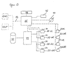
- FIGS. 3 to 6 illustrate different variants in schematic block diagrams for controlling a height leveling or vibration damping of the driver's cab 20th
- FIG. 3 illustrates a first variant of a control circuit for horizontal alignment the driver's cab 20.
- the left bellows 26-L and the right supporting bellows 26-R for angular alignment of the driver's cab 20 about the vehicle longitudinal axis driven.
- the angular orientation of the driver's cab 20 about the vehicle transverse axis takes place by means of a pressurization of support elements 27 an the rear axle 18 arranged ECAS system.
- Each of the bellows 26-L and 26-R has a separate control unit 34, with each of which the pressurization is controlled.
- the control units 34 of the bellows 26 are connected via electrical control lines (interrupted Lines) coupled to a central control circuit 36, which with an input device 38 is connected.
- control units 34 are, for example.
- Well-known solenoid valves in which hydraulic or pneumatic valves by means of an electromagnetic Control be switched.
- the central control circuit 36 continues to control a valve block 40, which may have, for example, a number of solenoid valves.
- a valve block 40 which may have, for example, a number of solenoid valves.
- the Umströmvor bland the compressed air between the Tragbälgen 26 and a compressed air supply 42 and an air supply variably controlled become.
- the lines for compressed air supply between the bellows 26, the valve block 40 and the compressed air supply 42 are executed in solid lines.
- FIG. 3 also shows an ECAS control unit 37, which is used to control the support elements 27 on the rear axle of the vehicle via the control unit 35 is used.
- the raising or lowering the chassis can by means of a pressurization or regulation of the support elements 27 done from a further compressed air reservoir 43.
- the ECAS controller 37 is preferably coupled via a CAN bus connection 39 to the central control circuit 36. However, this connection is not mandatory, as well as a separate control the bellows 26 and the support members 27 is possible. Possibly. can also do that ECAS control unit 37 are controlled manually by means of the input device 38.
- Damper elements 25-L and 25-R are respectively the left and right bellows 26-L and Assigned to 26-R. These damper elements 25-L, 25-R are after leveling the cabin by means of suitable control signals of the central control circuit 36 to their hardest damping level so that further body movements of the cabin largely can be suppressed.
- the chassis can over the ECAS system on the front and / or rear axle can be raised or lowered.
- the driver can control the orientation of the driver's cab 20 manually control without any additional sensors are present. Possibly.
- an optional tilt sensor 44 may allow automatic alignment. if the driver for this purpose by means of the input device 38, a corresponding control command gives.
- the inclusion of the chassis height adjustment is preferably carried out via appropriate Control commands (or CAN bus signals 39) from the central control circuit 36 to the ECAS controller 37.
- a second variant of the suspension control according to the invention is based on FIG. 4 clarified.
- the Position alignment of the driver's cab 20 in this variant preferably by means of an evaluation the signals of the tilt sensor 44 are controlled.
- the Control also be done manually.
- the Chassis are lowered by means of the ECAS system on the axle stop. This can also via CAN bus signals 39 from the central control circuit 36 to the ECAS control unit 37 done. Because the inclusion of the ECAS controller 37 as well as the CAN bus is optional, these components are shown with broken lines.
- damper elements 25-VL, 25-VR, 25-HL, 25-HR at its hardest level after the level control by means of the Tragbälge 26 provided.
- the damper elements 25 are normally common in this case controlled by the central control circuit 36. This can be a common Control line sufficient as a separate damper control during sleep mode does not make sense.
- the right front damper element 25-VR is the right front bellows 26-VR assigned, the left front damper element 25-VL the left front bellows 26-VL, etc, wherein the bellows 26 each in integrated Construction with the dampers 25 may be formed.
- An indicated with interrupted ruling additional sensor 45 is optional and can possibly enable the suspension control when the vehicle is moving for a To provide damping control.
- a third variant of the suspension control which is described in FIG Difference to the first two variants also for a tilt compensation of the driver's cab while driving the vehicle is suitable.
- the suspension control according to the invention according to Figure 5 also for pitch or roll compensation while driving the commercial vehicle are used, it may be useful in addition to the signals of a To evaluate acceleration sensor 46 and depending on the case delivered Signals a different control of the damping elements 25 of the support elements make.
- an acceleration sensor 46 is mentioned, so it is also a sensor equipment
- the plurality of acceleration sensors, a yaw rate sensor and / or a Tilt sensor includes. These sensors may already be part of existing vehicle equipment be, for example, a vehicle dynamics control.
- the sensor signals may possibly as Bus signals for additional evaluation in the central control circuit 36 are available be put.
- an electronic braking system (EBS) and / or an electronic stability control system (ESP) are evaluated.
- EBS electronic braking system
- ESP electronic stability control system
- the signals supplied by the speed sensor 48 can preferably via a Assignment rule of a map 52 of a specific body movement of the driver's cab 20 are assigned.
- a defined value assumes, it can be concluded that a defined pitching oscillation of the cabin. The same applies to different vehicle delays.
- the map 52 provides for an approximately correct control of the bellows to these pitching oscillations suppress.
- the signals supplied by the steering angle sensor 50 via a further Association rule of the map 52 a certain body movement of the cab 20 are assigned. If the lateral acceleration assumes a defined value, so it can be concluded that a defined swing vibration of the cabin. Since these body movements not only from the current steering angle, but also from depend on the current driving speed, the signals of the speed sensor 48 additionally evaluated.
- the map 52 provides an approximate correct control of the bellows in order to suppress the rolling oscillations.
- the advantage of the fourth variant of the invention described with reference to FIG Body control lies in particular in their simple structure.
- the activation of the Damper of the support elements 22 takes place here with a relatively simple control, so that no time-consuming and computationally intensive regulation is necessary.
- the sensor signals of the two sensors 48 and 50 from existing components a vehicle dynamics control (ESP) and / or an anti-lock device (ABS) win an electronically controlled brake system (EBS) (see Figure 5). These signals are usually available as CAN bus signals.
- ESP vehicle dynamics control
- ABS anti-lock device
- EBS electronically controlled brake system
- the output signal of the speed sensor 48 also from a Encoder for a speedometer and / or supplied for a tachograph become.
Landscapes
- Engineering & Computer Science (AREA)
- Mechanical Engineering (AREA)
- Chemical & Material Sciences (AREA)
- Combustion & Propulsion (AREA)
- Transportation (AREA)
- Vehicle Body Suspensions (AREA)
- Body Structure For Vehicles (AREA)
Abstract
Description
Die vorliegende Erfindung betrifft eine Aufhängung für eine Fahrerkabine eines Nutzfahrzeuges sowie ein Verfahren zur Steuerung einer derartigen Aufhängung.The present invention relates to a suspension for a driver's cab of a commercial vehicle and a method for controlling such a suspension.
Moderne Nutzfahrzeuge in sog. Frontlenkerbauweise weisen eine über Federn und/oder Dämpfer mit einem Fahrzeugrahmen verbundene Fahrerkabine auf, die oberhalb einer Vorderachse eines Zugfahrzeuges bzw. Nutzfahrzeuges angeordnet ist. Diese gefederte und/oder gedämpfte Aufhängung ist aufgrund von teilweise erheblichen vertikalen Beschleunigungen, die auf die Fahrerkabine einwirken, nahezu unverzichtbar. Sobald sich das Nutzfahrzeug im Stillstand befindet, kann sich diese Federung jedoch als Nachteil erweisen, da die Fahrerkabine bei Windeinflüssen, beispielsweise durch nahe vorbei fahrende Fahrzeuge ins Schwanken geraten kann. Bei einem im Fahrerhaus schlafenden Fahrer oder Passagier kann dies zu mehr oder weniger starken Beeinträchtigungen seiner Ruhephasen führen. Weiterhin kann bei einem an einer Steigung bzw. auf einer zur Seite geneigten Fahrbahn abgestellten Fahrzeug die hieraus resultierende Neigung der Fahrerkabine zu Komforteinbußen für den ruhenden Fahrer führen.Modern commercial vehicles in so-called. Frontlenkerbauweise have a via springs and / or Damper connected to a vehicle frame cab, which is above a front axle a towing vehicle or commercial vehicle is arranged. These spring-loaded and / or damped suspension is due in part to significant vertical accelerations, which act on the driver's cab, almost indispensable. As soon as that Commercial vehicle is at a standstill, this suspension can prove to be a disadvantage, because the driver's cab in the wind, for example, by nearby passing vehicles can waver. For a driver sleeping in the cab or Passenger can do so to more or less severe impairment of his periods of rest to lead. Furthermore, in an inclined on a slope or on a side Lane parked vehicle the resulting inclination of the driver's cab too Loss of comfort for the dormant driver lead.
Die DE 41 36 572 A1 beschreibt ein Fahrzeug mit einer Nivelliereinrichtung, mit deren Hilfe das Fahrzeug im Stillstand horizontal ausgerichtet werden kann. Die horizontale Ausrichtung des Fahrzeugrahmens und damit des gesamten Fahrzeuges erfolgt über verstellbare hydraulische Federbeine, welche den Achsaufhängungen des Fahrzeugs zugeordnet sind.DE 41 36 572 A1 describes a vehicle with a leveling device, with the help the vehicle can be aligned horizontally when stationary. The horizontal orientation of the vehicle frame and thus of the entire vehicle via adjustable hydraulic Suspension struts, which are assigned to the axle suspensions of the vehicle.
Die JP 071 49 256 A beschreibt ein Luftfederungssystem für ein Fahrzeug, bei dem mittels eines mechanisch wirkenden Neigungssensors eine horizontale Ausrichtung einer Fahrerkabine eingestellt werden kann.JP 071 49 256 A describes an air suspension system for a vehicle, in which means a mechanically acting inclination sensor, a horizontal orientation of a driver's cab can be adjusted.
Ein erstes Ziel der vorliegenden Erfindung besteht darin, ein einfach aufgebautes und einfach zu bedienendes Steuerungssystem bzw. -verfahren für eine Aufhängung einer Fahrerkabine zur Verfügung zu stellen, die eine weitgehend horizontale Ausrichtung der Fahrerkabine in nahezu jeder Fahrzeugposition bei dessen Stillstand ermöglicht.A first object of the present invention is a simple and simple to operate control system or method for a suspension of a cab to provide a largely horizontal orientation of the cab enabled in almost any vehicle position at its stoppage.
Dieses erste Ziel der Erfindung wird mit dem Gegenstand des unabhängigen Anspruchs 1 bzw. mit einem Verfahren gemäß Anspruch 13 erreicht. Bei der erfindungsgemäßen Aufhängung für eine Fahrerkabine eines Nutzfahrzeuges mit den Merkmalen des Anspruchs 1 ist vorgesehen, dass eine annähernd horizontale Lage der Fahrerkabine im Stillstand des Nutzfahrzeuges durch eine Einstellung des jeweiligen Hubs von Tragelementen und/oder von Aufhängungselemente eines Fahrwerks des Nutzfahrzeuges realisierbar ist. Als Tragelemente können insbesondere mit hydraulischem und/oder pneumatischem Druck beaufschlagbare Tragbälge bzw. Federbälge zum Einsatz kommen, die zwischen der Fahrerkabine und dem Fahrgestellrahmen angeordnet sind.This first object of the invention is achieved with the subject matter of independent claim 1 or achieved by a method according to claim 13. In the suspension according to the invention for a driver's cab of a commercial vehicle with the features of claim 1 is provided that an approximately horizontal position of the cab at standstill of Commercial vehicle by adjusting the respective stroke of support elements and / or is realized by suspension elements of a chassis of the commercial vehicle. As support elements can be acted upon in particular by hydraulic and / or pneumatic pressure Tragbälge or bellows are used, between the driver's cab and the chassis frame are arranged.
Unter einem Tragelement wird im vorliegenden Zusammenhang ein Bauteil verstanden, das eine Luftfeder, bspw. einen Federbalg, sowie ein Dämpferelement, bspw. einen hydraulisch wirkenden Stoßdämpfer, umfasst. Ggf. kann das Tragelement darüber hinaus einen Wegsensor zur Erfassung einer aktuellen Auslenkung des Tragelements aufweisen.Under a support member is understood in the present context, a component that an air spring, for example. A bellows, and a damper element, eg. A hydraulic acting shock absorber, includes. Possibly. In addition, the support element can be a displacement sensor to detect a current deflection of the support element.
Bei einer pneumatisch wirkenden Aufhängung mit Federbälgen können beispielsweise durch manuelle Steuerung seitens des Fahrers einzelne dieser Federbälge mit einem erhöhten Druck beaufschlagt werden, während aus anderen Federbälgen die darin gespeicherte Druckluft abgelassen wird. Hierdurch kann auf einfache Weise eine horizontale Ausrichtung der Fahrerkabine hergestellt werden. Gleiches funktioniert auch mit einem hydraulisch wirkenden System, bei dem die Fahrerkabine über hydraulische wirkende Feder- und/oder Dämpferelemente mit dem Fahrzeugrahmen verbunden ist.In a pneumatic suspension with bellows can, for example, by manual control by the driver of each of these bellows with an increased Pressure are applied, while from other bellows stored therein Compressed air is released. This can easily be a horizontal orientation the driver's cab are made. The same thing works with a hydraulically acting System in which the driver's cab via hydraulic acting spring and / or Damper elements is connected to the vehicle frame.
Mittels der erfindungsgemäßen Aufhängung kann der Fahrer das Fahrerhaus während des Stillstandes des Fahrzeugs in eine horizontale Lage bringen. Das Fahrerhaus kann bei diesem sog. Schlafmodus unabhängig von der Bodenneigung waagrecht eingestellt werden. Auf diese Weise kann gewährleistet werden, dass der Fahrer bei den gesetzlich vorgeschriebenen Ruhepausen ein Höchstmaß an Komfort genießen kann. Bei einer ersten Variante der Aufhängungssteuerung kann der Fahrer einzelne Tragelemente manuell in ihrem Hub einstellen, bis die Kabine horizontal ausgerichtet ist. Dies kann insbesondere manuell erfolgen. Ein Neigungs- oder Lagesensor ist hierbei nicht zwingend notwendig, da der Fahrer die Fahrzeugneigung selbst beurteilen und die Ausrichtung der Fahrerkabine entsprechend seiner eigenen Wahrnehmung vornehmen kann.By means of the suspension according to the invention, the driver can use the cab during the Standstill of the vehicle in a horizontal position. The cab can be at this so-called sleep mode can be adjusted horizontally regardless of the floor inclination. In this way it can be ensured that the driver is required by law Rest breaks can enjoy the highest level of comfort. In a first variant the suspension control, the driver can manually individual support elements in their Adjust the stroke until the cabin is aligned horizontally. This can be done manually in particular respectively. A tilt or position sensor is not absolutely necessary, as the driver judge the vehicle inclination itself and the orientation of the cab accordingly his own perception.
Neben einer manuellen Steuerung des Hubs der Tragelemente und/oder der Aufhängungselemente des Fahrwerks kann auch eine automatische Steuerung vorgesehen sein, die beispielsweise die Signale eines Lage- bzw. Neigungssensors auswertet und daraus eine Druckbeaufschlagung der einzelnen Trag- oder Aufhängungselemente herleitet. In addition to manual control of the stroke of the support elements and / or the suspension elements The chassis can also be provided an automatic control, for example evaluates the signals of a position or inclination sensor and from it a Pressurization of the individual suspension or suspension elements derives.
Eine einfache Ausführungsform der Erfindung kann vorsehen, dass eine Ausrichtung der Fahrerkabine um eine Längsachse des Nutzfahrzeuges ausschließlich über eine unterschiedliche Druckbeaufschlagung der Tragelemente erfolgt, während eine Ausrichtung um eine Querachse des Fahrzeugs mittels einer Absenkung oder Anhebung des Chassis gegen die Hinterachse des Fahrzeugs erfolgt. Die Ausrichtung um die Längsachse erfolgt hierbei mittels linker bzw. rechter Tragelemente, während die Ausrichtung um die Querachse mittels einer Höhenverstellung der Aufhängungselemente der Fahrzeughinterachse erfolgt. Diese Ausrichtung um die Fahrzeugquerachse kann in vorteilhafter Weise mittels eines bereits vorhandenen ECAS-Systems (ECAS, Electronically Controlled Air Suspension) erfolgen, bei dem die Fahrzeughinterachse mittels pneumatisch wirkender Tragbälge gegen den Rahmen abgestützt ist.A simple embodiment of the invention may provide that an orientation of the Driver's cab around a longitudinal axis of the commercial vehicle exclusively via a different Pressurization of the support elements takes place while an alignment order a transverse axis of the vehicle by means of lowering or raising the chassis against the rear axle of the vehicle takes place. The alignment about the longitudinal axis takes place here by means of left or right support elements, while the alignment about the transverse axis by means of a height adjustment of the suspension elements of the vehicle rear axle takes place. These Alignment about the vehicle transverse axis can advantageously by means of an already existing ECAS system (ECAS, Electronically Controlled Air Suspension) the vehicle's rear axle by means of pneumatically-acting support bellows against the frame is supported.
Bei einer alternativen Variante der erfindungsgemäßen Aufhängung wird das Fahrerhaus über alle drei oder vier vorhandenen Tragelemente bzw. Tragbälge in eine horizontale Lage gebracht. Ein ECAS-System zur Höhenregulierung der Fahrzeughinterachse ist hierbei nicht notwendig. Vorteilhaft kann diese Variante insbesondere bei Fahrzeugen eingesetzt werden, die am Chassis mit herkömmlichen Stahlfedern (Schrauben- und/oder Blattfederelementen) ausgestattet sind. Allerdings muss die Ansteuerung der Tragelemente zur richtigen Ausrichtung des Fahrerhauses in geeigneter Weise miteinander gekoppelt sein. Auch diese Variante des Systems kann sowohl manuell als auch automatisch gesteuert werden.In an alternative variant of the suspension according to the invention, the cab over all three or four existing support elements or Tragbälge in a horizontal position brought. An ECAS system for height adjustment of the vehicle rear axle is not necessary. Advantageously, this variant can be used in particular for vehicles, on the chassis with conventional steel springs (screw and / or leaf spring elements) are equipped. However, the control of the support elements for the correct orientation the cab be suitably coupled together. Also this variant The system can be controlled both manually and automatically.
Weiterhin kann es von Vorteil sein, wenn die Tragelemente nach einer erfolgten Lagejustierung in ihrer Dämpfungscharakteristik dahingehend einstellbar sind, dass eine Bewegung der Fahrerkabine weitgehend oder vollständig unterdrückbar ist. Dies kann insbesondere durch eine geeignete Dämpferhartstellung erreicht werden, bei der eine maximale Dämpferverhärtung angestrebt wird. Hierdurch kann beispielsweise eine durch Wind hervorgerufene Schwankbewegung der Fahrerkabine weitgehend unterdrückt werden. Gleichermaßen können hierdurch Schwankbewegungen unterdrückt werden, die durch Windkräfte vorbei fahrender Fahrzeuge wie LKWs o. dgl. verursacht werden. Zusätzlich können Bewegungen der Fahrerkabine, ausgelöst durch Bewegungen oder Gewichtsverlagerungen von Personen in der Kabine, unterdrückt werden. Es kann ggf. auch vorgesehen sein, dass die Fahrerkabine mechanisch verriegelbar ist. Zusätzlich kann das Fahrwerk gegen einen mechanischen Anschlag (sog. Pufferanschlag bzw. Achsanschlag) gefahren werden. Furthermore, it may be advantageous if the support elements after a successful adjustment position are adjustable in their damping characteristic to the effect that a movement the driver's cab is largely or completely suppressible. This can be special be achieved by a suitable damper hard position, in which a maximum Dämpferverhärtung is sought. As a result, for example, caused by wind Schwankbewegung the cab are largely suppressed. Likewise As a result, fluctuations are suppressed, passing by wind forces passing Vehicles such as trucks o. The like. Are caused. In addition, movements of the Cab, triggered by movements or weight transfers of persons in the cabin, be suppressed. It may possibly also be provided that the driver's cab is mechanically lockable. In addition, the suspension against a mechanical stop (so-called buffer stop or axle stop) are driven.
Neben einer Höhenregulierung des Chassis an der Hinterachse kann optional auch eine zusätzliche Höhenregulierung an der Vorderachse vorgesehen sein, vorzugsweise mittels eines ebenfalls bereits vorhandenen ECAS-Systems an der Vorderachse.In addition to a height adjustment of the chassis on the rear axle can optionally also a be provided additional height adjustment on the front axle, preferably by means an already existing ECAS system on the front axle.
Eine weitere Ausgestaltung der Erfindung sieht vor, dass eine automatische Ausregelung von Schwankbewegungen mittels einer variablen Ansteuerung der Tragelemente der Fahrerkabine erfolgen kann. Das Fahrzeugchassis kann zur Erreichung einer Wankstabilisierung mittels des ECAS-Systems auf den Achsanschlag (Vorder- und/oder Hinterachse) abgesenkt werden. Der Regelvorgang der Wankstabilisierung kann dadurch erfolgen, dass die Tragbälge be- oder entlüftet und im eingestellten Zustand gehalten werden, so dass die Fahrerkabine horizontal ausgerichtet ist. Anschließend werden die Dämpfungselemente auf ihre härteste Stufe eingestellt bzw. blockiert. Hierdurch können Windeinflüsse oder auch Schaukeln aufgrund von Lastverteilungen in der Kabine vermindert bzw. vermieden werden. Als einstellbare Dämpfer können bspw. sog. CDC-Dämpfer (CDC, Continuous Damping Control) eingesetzt werden, die in ihrer Dämpfungscharakteristik in weiten Grenzen variierbar sind.A further embodiment of the invention provides that an automatic control of swaying movements by means of a variable control of the supporting elements of the driver's cab can be done. The vehicle chassis can be used to achieve roll stabilization lowered by the ECAS system on the axle stop (front and / or rear axle) become. The control process of roll stabilization can be done by the Bellows are vented and kept in set condition, leaving the cab is aligned horizontally. Subsequently, the damping elements on their Hardest level set or blocked. This can cause wind or swings be reduced or avoided due to load distributions in the cabin. When adjustable dampers can, for example, so-called. CDC dampers (CDC, Continuous Damping Control) can be used, which are variable in their damping characteristics within wide limits.
Die Sensierung der Lage und/oder der Bewegungen der Fahrerkabine kann wahlweise mittels eines, der Fahrerkabine zugeordneten bzw. dort angeordneten Lagesensors und/oder mittels Wegsensoren erfolgen, die den jeweiligen Tragelementen zugeordnet bzw. dort integriert sind. Als solche Wegsensoren kommen insbesondere induktive Sensoren oder Ultraschallsensoren in Frage, die innerhalb der Luftbälge angeordnet sein können. Wahlweise oder zusätzlich kann ein induktiv arbeitender Wegsensor an einer geeigneten Stelle am Chassis angeordnet sein.The sensing of the position and / or the movements of the driver's cab can optionally by means of one, the driver's cab assigned or arranged there position sensor and / or be done by means of displacement sensors associated with the respective support elements or integrated there are. As such displacement sensors come in particular inductive sensors or ultrasonic sensors in question, which may be arranged inside the bellows. Optional or in addition, an inductively working displacement sensor at a suitable location on Chassis be arranged.
Die weiteren bevorzugten Ausgestaltungen des erfindungsgemäßen Verfahrens verwenden die bereits erwähnten unterschiedlichen Merkmale, so dass sie hier nicht nochmals erwähnt werden müssen.Use the further preferred embodiments of the method according to the invention the already mentioned different features, so they will not be mentioned again here Need to become.
Ein weiteres Ziel der Erfindung besteht darin, eine Aufhängungssteuerung für eine Fahrerkabine eines Nutzfahrzeuges zur Verfügung zu stellen, mit der auf einfache Weise Nick-oder Rollbewegungen aufgrund unterschiedlicher Fahrzustände des Nutzfahrzeuges gedämpft bzw. unterdrückt werden können.Another object of the invention is a suspension control for a driver's cab a commercial vehicle to provide, with the easy Nick or Rolling damped due to different driving conditions of the commercial vehicle or can be suppressed.
Dieses weitere Ziel der Erfindung wird mit den Gegenständen der unanhängigen Ansprüche
19 und 20 bzw. 25 und 26 erreicht, wonach vorgesehen ist, dass die Fahrzustandsänderungen
des Nutzfahrzeuges aus den Ausgangssignalen wenigstens eines Beschleunigungssensors
und/oder aus den Ausgangssignalen eines Tachogenerators und/oder eines Lenkwinkelsensors
herleitbar sind.This further object of the invention is achieved with the objects of the
Bei einer vorgesehenen Auswertung der Signale eines Beschleunigungssensors kann ein Ausgangsignal beispielsweise aus den Bussignalen einer Blockierverhinderungseinrichtung (ABS), einer Fahrdynamikregelung (ESP) oder aus den Ausgangssignalen eines separaten Beschleunigungssensors bzw. mehrerer separater Beschleunigungssensoren hergeleitet werden. Bei einer alternativen Ausgestaltung, bei der lediglich die Signale eines Tachogenerators ausgewertet werden und daraus durch Differenzieren nach der Zeit (dv/dt) eine Fahrzeugbeschleunigung hergeleitet wird, können unterschiedliche Signale in einem Kennfeld abgelegt sein, woraus entsprechende Bewegungen der Fahrerkabine herleitbar sind. Mittels der erfindungsgemäßen Aufhängung bzw. des erfindungsgemäßen Verfahrens zur Aufhängungssteuerung können unerwünschte Nickbewegungen der Fahrerkabine aufgrund eines Anfahr- oder Bremsvorganges und/oder Rollbewegungen aufgrund einer Kurvenfahrt ausgeglichen werden. Darüber hinaus ist es möglich, nahezu beliebige Fahrzustandsänderungen zu sensieren und in Abhängigkeit davon eine Stabilisierung der Fahrerkabinenaufhängung zu erreichen, so dass diese möglichst geringen Schaukel, Nick- und Vertikalbewegungen ausgesetzt ist.In an intended evaluation of the signals of an acceleration sensor can be Output signal, for example, from the bus signals of a blocking prevention device (ABS), a vehicle dynamics control (ESP) or from the output signals of a separate Acceleration sensor or more separate acceleration sensors derived become. In an alternative embodiment, in which only the signals of a tachogenerator be evaluated and from this by differentiating after the time (dv / dt) a vehicle acceleration can derive different signals in a map be stored, from which corresponding movements of the driver's cab are derivable. through the suspension according to the invention or the method according to the invention for suspension control may cause undesirable pitching of the cab due to a Starting or braking and / or rolling movements due to cornering compensated become. In addition, it is possible to almost any driving state changes to sense and depending on a stabilization of the cab suspension to achieve such a minimal swing, pitching and vertical movements is exposed.
Die Fahrzustandsänderungen können mittels eines Beschleunigungssensor, mehrerer Beschleunigungssensoren (als Ersatz für einen Gierratensensor bzw. zur Nachbildung dessen Ausgangssignale) und/oder eines Gierratensensors erfasst werden. Diese Sensoren können als separate Systembestandteile im Fahrzeug vorgesehen sein. Die notwendigen Signale zur Ansteuerung der Fahrerkabinenaufhängung können jedoch in vorteilhafter Weise auch aus den Sensorsignalen einer Fahrdynamikregelung (bspw. sog. ESP) gewonnen werden, die üblicherweise als Bussignale eines CAN-Bus-Systems zur Verfügung stehen.The driving state changes may be by means of an acceleration sensor, a plurality of acceleration sensors (as a substitute for a yaw rate sensor or to replicate it Output signals) and / or a yaw rate sensor are detected. These sensors can be provided as a separate system components in the vehicle. The necessary signals to control the cab suspension but can also be in an advantageous manner be obtained from the sensor signals of a vehicle dynamics control (eg so-called ESP), which are usually available as bus signals of a CAN bus system.
Eine besonders vorteilhafte Variante der Erfindung sieht vor, dass Fahrzustandsänderungen, die typischerweise zu unerwünschten Nick- oder Rollbewegungen der Fahrerkabine führen, aus den Signalen eines Sensors hergeleitet werden, der ein von der Fahrgeschwindigkeit bzw. ein von einem Lenkwinkel abhängiges Ausgangssignal liefert. Ein solcher Geschwindigkeitssensor kann bspw. ein Drehratensensor einer Blockierverhinderungseinrichtung eines Bremssystems o. dgl. sein, der aus den Raddrehzahlen Eingangsgrößen für ein sog. Anti-Blockier-System gewinnt. Der Lenkwinkelsensor kann bspw. Bestandteil einer bereits vorhandenen Fahrdynamikregelung sein. Auf diese Weise lässt sich eine bereits vorhandene Fahrzeugausstattung für die Zwecke der vorliegenden Erfindung vorteilhaft nutzen. Mittels einer Zuordnungsvorschrift, bspw. in Form eines Kennfeldes, lassen sich die unterschiedlichen Sensorsignale jeweils unterschiedlichen Aufbaubewegungen der Fahrerkabine zuordnen. Diese fahrzeug- und aufbauspezifischen Zusammenhänge lassen sich mittels geeigneter Berechnungen, Abschätzungen und/oder mittels Versuchsreihen ermitteln, so dass sich für unterschiedliche Fahrzeuge und Aufbauten jeweils unterschiedliche Kennfelder ermitteln lassen. Die Nick- und Wankstabilisierung der Fahrzeugkabine lässt sich auf diese Weise mittels eines relativ einfachen und reaktionsschnellen Steuersystems realisieren, das keine aufwändige Rechenarbeit eines Regelsystems benötigt.A particularly advantageous variant of the invention provides that driving state changes, which typically lead to undesirable pitching or rolling movements of the driver's cab, be derived from the signals of a sensor, the one of the driving speed or an output signal dependent on a steering angle. Such a speed sensor For example, a rotation rate sensor of a blocking prevention device of Be brake system o. The like., From the wheel speeds input variables for a so-called. Anti-lock system wins. The steering angle sensor can, for example, part of an already be existing vehicle dynamics control. In this way, an already existing Use vehicle equipment for the purposes of the present invention advantageous. through an assignment rule, for example. In the form of a map, the different Sensor signals respectively different body movements of the driver's cab assign. These vehicle and body-specific relationships can be determined by means of appropriate calculations, estimates and / or determine by means of test series, so that for different vehicles and bodies each different maps can be determined. The pitch and roll stabilization of the vehicle cab can be based on this Realize manner by means of a relatively simple and responsive control system, the no elaborate computational work of a control system needed.
Die Erfindung umfasst jedoch gleichermaßen Systeme, bei denen eine geregelte Ansteuerung der Tragelemente der Fahrerkabine erfolgt. Hierzu können die Tragelemente ggf. mit Wegsensoren versehen sein, welche die aktuelle Auslenkung jedes Tragelements sensieren und ein entsprechendes Sensorsignal liefern.However, the invention equally includes systems in which a controlled drive the supporting elements of the cab takes place. For this purpose, the support elements possibly with Be provided displacement sensors, which sense the current deflection of each support element and provide a corresponding sensor signal.
Die Erfindung wird nachfolgend anhand eines bevorzugten Ausführungsbeispiels unter Bezugnahme auf die beiliegenden Zeichnungen näher erläutert. Dabei zeigt:
- Figur 1
- eine schematische Darstellung eines Nutzfahrzeuges in Frontlenkerbauweise, das eine über einer Vorderachse angeordnete Fahrerkabine aufweist,
- Figur 2
- eine schematische Perspektivdarstellung eines Teils eines Rahmengestells des Nutzfahrzeuges inklusive der dazugehörigen Fahrerhauslagerung, jedoch ohne Fahrerhausbodenblech,
- Figur 3
- ein schematisches Blockschaltbild einer ersten Variante einer erfindungsgemäßen Aufhängungssteuerung für die Fahrerkabine,
Figur 4- ein schematisches Blockschaltbild einer zweiten Variante der Aufhängungssteuerung und
- Figur 5
- ein schematisches Blockschaltbild einer dritten Variante der Aufhängungssteuerung und
Figur 6- ein schematisches Blockschaltbild einer vierten Variante der Aufhängungssteuerung.
- FIG. 1
- a schematic representation of a commercial vehicle in front-wheel design, which has a driver's cab arranged above a front axle,
- FIG. 2
- a schematic perspective view of a portion of a frame of the commercial vehicle including the associated cab suspension, but without cab floor panel,
- FIG. 3
- FIG. 2 shows a schematic block diagram of a first variant of a suspension control according to the invention for the driver's cab, FIG.
- FIG. 4
- a schematic block diagram of a second variant of the suspension control and
- FIG. 5
- a schematic block diagram of a third variant of the suspension control and
- FIG. 6
- a schematic block diagram of a fourth variant of the suspension control.
Die schematische Darstellung der Figur 1 zeigt eine Sattelzugmaschine in sog. Frontlenkerbauweise,
die im Folgenden allgemein als Nutzfahrzeug 10 bezeichnet wird. Die Erfindung
beschränkt sich jedoch keineswegs auf sog. Frontlenkerfahrzeuge, sondern lässt sich in
gleicher Weise an sog. Haubenfahrzeugen realisieren, bei denen die Fahrerkabine hinter
einem Antriebsmotor angeordnet ist. Das Nutzfahrzeug 10 kann selbstverständlich auch
einen anderen Aufbau aufweisen als den gezeigten. So kann es bspw. Tandemachsen vorne
und/oder hinten oder hintere Drillingsachsen aufweisen. Die erfindungsgemäße Aufhängung
kann in vorteilhafter Weise bei allen denkbaren Nutzfahrzeug- und Sonderfahrzeugvarianten
eingesetzt werden.The schematic representation of FIG. 1 shows a tractor-trailer in so-called front-link construction,
which is generally referred to below as a
Das Nutzfahrzeug 10 weist einen Fahrgestellrahmen 12 (sog. Chassis) auf, der üblicherweise
mindestens zwei miteinander verstrebte Längsträger 14 umfasst. Am Fahrgestellrahmen
12 sind jeweils Aufhängungselemente (nicht dargestellt) für eine Vorderachse 16 sowie für
eine Hinterachse 18 verankert. Eine Fahrerkabine 20 ist über mehrere Tragelemente 22
gefedert und/oder gedämpft mit dem Fahrgestellrahmen 12 verbunden. Wenn im vorliegenden
Zusammenhang von Tragelementen 22 die Rede ist, so ist damit grundsätzlich ein
Luftfeder-Dämpfungsmodul gemeint, bei dem Luftfedern und hydraulische bzw. pneumatische
Dämpfungselemente in kombinierter Bauweise zusammengefasst sind. Zusätzlich können
die Tragelemente noch mit geeigneten integrierten Wegsensoren versehen sein, die
bspw. eine Auslenkung der Tragelemente 22 mittels Ultraschallsignalauswertung erfassen
und daraus ein Sensorsignal bilden können. Die Wegsensoren können bspw. auch eine induktive
Wegerfassung vorsehen.The
Typisch für die Frontlenkerbauweise ist, dass die Fahrerkabine 20 über der Vorderachse 16
angeordnet ist. Das in Figur 1 dargestellte Nutzfahrzeug 10 ist als Zugfahrzeug ausgestaltet.
Hierbei ist im Bereich der Hinterachse 18 ein Kupplungselement 24 für einen Aufliegeanhänger
(nicht dargestellt) angeordnet.Typical of the front-wheel design is that the driver's
Bei einem Stillstand des Nutzfahrzeuges 10 kann die Fahrerkabine 20 als Ruheraum für
einen Fahrer genutzt werden, wenn dieser beispielsweise Ruhe- oder Übernachtungspausen
einlegt. Hierbei kann es vorkommen, dass das Nutzfahrzeug 10 auf geneigtem oder unebenem
Untergrund steht, so dass die Fahrerkabine 20 nicht horizontal ausgerichtet ist. Dies
kann zu Komforteinbußen für den ruhenden Fahrer führen.At a standstill of the
Ein weiteres Problem hinsichtlich eines optimalen Ruhekomforts kann dadurch entstehen,
dass die gefedert und/oder gedämpft abgestützte Fahrerkabine 20 bei Windböen und/oder
bei Windeinflüssen durch vorbeifahrende Fahrzeuge o. dgl. ins Schwanken geraten kann.
Derartige Schwankungen können auch durch Bewegungen der Kabinenpassagiere ausgelöst
werden. Aus diesem Grund sieht die vorliegende Erfindung vor, dass die Fahrerkabine
20 im Stillstand des Fahrzeugs 10 horizontal ausgerichtet und/oder stärker gedämpft
(Dämpfer auf härteste Stufe gestellt) werden kann, beispielsweise durch eine manuelle Ansteuerung
der Tragelemente 22, die im gezeigten Ausführungsbeispiel jeweils pneumatisch
wirkende Federbälge 26 aufweisen, wie dies anhand der schematischen Darstellung der
Figur 2 verdeutlicht ist.Another problem in terms of optimal resting comfort can arise,
that the sprung and / or damped supported
Die schematische Darstellung der Figur 2 zeigt die Anordnung der Tragelemente 22, die hier
als vier Federbälge bzw. Tragbälge 26 an den beiden Längsträgern 14 des Fahrgestellrahmens
12 dargestellt sind, an deren oberem Ende jeweils ein Verankerungsteil 28 angeordnet
ist. Die Fahrerkabine 20 ist an ihrer Unterseite mit den Verankerungsteilen 28 der Tragbälge
26 verbunden, so dass eine gleichmäßige Abstützung der Fahrerkabine 20 am Fahrgestellrahmen
12 ermöglicht ist. Die vier Federbälge 26 ermöglichen durch individuelle Ansteuerung
bzw. Druckbeaufschlagung eine horizontale Ausrichtung der Fahrerkabine 20 unabhängig
von einer ggf. geneigten Ausrichtung des Fahrzeugrahmens 12. Gelenkverbindungen
zwischen den Tragbälgen 26 und den Verankerungsteilen 28 sind an der Vorderseite der
Fahrerkabine durch einen Stabilisator 30 verbunden. Auf diese Weise ist die jeweilige Neigung
der Fahrerkabine 20 gegenüber dem Fahrgestellrahmen 12 exakt definiert.The schematic representation of Figure 2 shows the arrangement of the
Eine einfache Ausgestaltung der Erfindung kann vorsehen, dass die Fahrerkabine 20 in
Fahrzeuglängsachse über die linken und die rechten Federbälge 26 und in Fahrzeugquerachse
über eine Anhebung oder Absenkung des Chassis an der Hinterachse 18 in eine horizontale
Lage gebracht werden kann. Zur Höhenverstellung der Hinterachse 18 eignet sich
bspw. ein Luftfedersystem mit Federbälgen, ein sog. ECAS-System, bei dem die Federhöhe
der Federbälge an der Hinterachse 18 variabel einstellbar ist.A simple embodiment of the invention can provide that the driver's
In ähnlicher Weise können die Tragelemente 22 zur Schwingungsregelung der Fahrerkabine
20 eingesetzt werden. Derartige Nickschwingungen entstehen insbesondere beim stärkeren
Beschleunigen und Verzögern des Fahrzeugs 10. Auch Wank- oder Rollbewegungen um die
Fahrzeuglängsachse können durch eine gezielte Ansteuerung der einzelnen Dämpfungselemente
der jeweiligen Tragbälge 22 zumindest teilweise unterdrückt werden. Ein hoher
Kabinenschwerpunkt begünstigt derartige Relativbewegungen zwischen Fahrzeugrahmen
und Fahrerkabine zusätzlich.Similarly, the
Nicht dargestellt sind in Figur 1 und 2 die Stoßdämpferelemente, die normalerweise den
einzelnen Tragelementen zugeordnet sind und die jeweils für eine Schwingungsdämpfung
der Fahrerkabine 20 sorgen. Wahlweise können diese Stoßdämpfer in ihrer Dämpfungscharakteristik
verstellbar sein. Insbesondere während des Stillstandes des Fahrzeugs ist eine
möglichst "harte" Dämpfungscharakteristik wünschenswert, um die Bewegungen der in horizontale
Lage gebrachten Kabine möglichst stark zu dämpfen. Derartige Dämpferelemente
sind als sog. CDC-Dämpfer bekannt.Not shown in Figures 1 and 2, the shock absorber elements, which normally the
individual support elements are assigned and each for a vibration damping
the driver's
Die Figuren 3 bis 6 verdeutlichen in schematischen Blockschaltbildern verschiedene Varianten zur Steuerung einer Höhennivellierung bzw. zur Schwingungsdämpfung der Fahrerkabine 20.FIGS. 3 to 6 illustrate different variants in schematic block diagrams for controlling a height leveling or vibration damping of the driver's cab 20th
Die Figur 3 verdeutlicht eine erste Variante einer Steuerschaltung zur horizontalen Ausrichtung
der Fahrerkabine 20. Bei dieser einfachsten Variante werden die linken Tragbälge 26-L
sowie die rechten Tragbälge 26-R zur Winkelausrichtung der Fahrerkabine 20 um die Fahrzeuglängsachse
angesteuert. Die Winkelausrichtung der Fahrerkabine 20 um die Fahrzeugquerachse
erfolgt mittels einer Druckbeaufschlagung von Tragelementen 27 eines an
der Hinterachse 18 angeordneten ECAS-Systems. Jeder der Tragbälge 26-L und 26-R weist
eine separate Steuereinheit 34 auf, mit der jeweils die Druckbeaufschlagung gesteuert wird.
Die Steuereinheiten 34 der Tragbälge 26 sind über elektrische Steuerleitungen (unterbrochene
Linien) mit einer zentralen Steuerschaltung 36 gekoppelt, die mit einer Eingabeeinrichtung
38 verbunden ist. Als Steuereinheiten 34 eignen sich bspw. bekannte Magnetventile,
bei denen hydraulische oder pneumatische Ventile mittels einer elektromagnetischen
Ansteuerung geschaltet werden.FIG. 3 illustrates a first variant of a control circuit for horizontal alignment
the driver's
Mittels der Eingabeeinrichtung 38 kann der Fahrer die gewünschten Steuerbefehle an die
zentrale Steuerschaltung 36 übermitteln. Die zentrale Steuerschaltung 36 steuert weiterhin
einen Ventilblock 40 an, der bspw. eine Reihe von Magnetventilen aufweisen kann. Mit Hilfe
des steuerbaren Ventilblocks 40 können die Umströmvorgänge der Druckluft zwischen den
Tragbälgen 26 und einer Druckluftversorgung 42 bzw. einem Luftvorrat variabel gesteuert
werden. Die Leitungen zur Druckluftversorgung zwischen den Tragbälgen 26, dem Ventilblock
40 und der Druckluftversorgung 42 sind in durchgezogenen Linien ausgeführt.By means of the
Figur 3 zeigt weiterhin ein ECAS-Steuergerät 37, das zur Ansteuerung der Tragelemente 27
an der Hinterachse des Fahrzeugs über die Steuereinheit 35 dient. Das Anheben bzw. Absenken
des Chassis kann mittels einer Druckbeaufschlagung bzw. -regulierung der Tragelemente
27 aus einem weiteren Druckluftvorrat 43 erfolgen. Das ECAS-Steuergerät 37 ist
vorzugsweise über eine CAN-Bus-Verbindung 39 mit der zentralen Steuerschaltung 36 gekoppelt.
Diese Verbindung ist jedoch nicht zwingend notwendig, da auch eine separate Ansteuerung
der Tragbälge 26 und der Tragelemente 27 möglich ist. Ggf. kann auch das
ECAS-Steuergerät 37 mittels der Eingabeeinrichtung 38 manuell angesteuert werden.FIG. 3 also shows an
Dämpferelemente 25-L und 25-R sind jeweils den linken und rechten Tragbälgen 26-L bzw.
26-R zugeordnet. Diese Dämpferelemente 25-L, 25-R werden nach erfolgter Niveauregulierung
der Kabine mittels geeigneter Steuersignale der zentralen Steuerschaltung 36 auf ihre
härteste Dämpfungsstufe gestellt, so dass weitere Aufbaubewegungen der Kabine weitgehend
unterdrückt werden können.Damper elements 25-L and 25-R are respectively the left and right bellows 26-L and
Assigned to 26-R. These damper elements 25-L, 25-R are after leveling
the cabin by means of suitable control signals of the
Bei Nutzfahrzeugen mit Blatt- oder Schraubenfederung an der Vorderachse und mit Luftfedem (ECAS-System) an der Hinterachse erfolgt die Höhenverstellung derart, dass das Chassis um die Querachse mittels der Hinterachsaufhängung in etwa horizontal ausgerichtet wird. Die horizontale Ausrichtung der Kabine erfolgt dann über die Tragelemente 26-L und 26-R. Bei Nutzfahrzeugen mit Luftfederung an allen Achsen kann das Chassis über das ECAS-System an der Vorder- und/oder Hinterachse angehoben bzw. abgesenkt werden.For commercial vehicles with leaf or coil suspension on the front axle and with air springs (ECAS system) on the rear axle is the height adjustment such that the Chassis about the transverse axis by means of the rear suspension in approximately horizontally aligned becomes. The horizontal orientation of the cabin is then via the support members 26-L and 26-R. For commercial vehicles with air suspension on all axles, the chassis can over the ECAS system on the front and / or rear axle can be raised or lowered.
Wenn bei den Erläuterungen der Figur 3 von rechten und linken Tragbälgen 26-L und 26-R sowie von rechten und linken Dämpfern 25-L und 25-R die Rede ist, so sind damit normalerweise vordere und hintere Elemente jeweils einer Seite (links oder rechts) gemeint, die in ihrer Ansteuerung jeweils miteinander gekoppelt sind.If in the explanations of Figure 3 right and left Tragbälgen 26-L and 26-R as well as right and left dampers 25-L and 25-R is the talk, so are usually front and back elements of each side (left or right) meant in their control are each coupled together.
In einer einfachen und kostengünstigen Variante kann der Fahrer die Ausrichtung der Fahrerkabine
20 manuell steuern, ohne dass irgendwelche weiteren Sensoren vorhanden sind.
Ggf. kann ein optionaler Neigungssensor 44 eine automatische Ausrichtung ermöglichen,
wenn der Fahrer hierzu mittels der Eingabeeinrichtung 38 einen entsprechenden Steuerbefehl
gibt. Die Einbeziehung der Chassis-Höhenregulierung erfolgt vorzugsweise über entsprechende
Steuerbefehle (bzw. CAN-Bus-Signale 39) von der zentralen Steuerschaltung
36 an das ECAS-Steuergerät 37.In a simple and inexpensive variant, the driver can control the orientation of the driver's
Eine zweite Variante der erfindungsgemäßen Aufhängungssteuerung ist anhand der Figur 4
verdeutlicht. Bei dieser Variante wird die Fahrerkabine 20 über alle vier Tragbälge 26 in ihrer
Lage ausgerichtet. Es werden neben den beiden vorderen Tragbälgen 26-VL und 26-VR
auch die beiden hinteren Tragbälge 26-HL und 26-HR von der zentralen Steuerschaltung 36
angesteuert. Aufgrund des komplexeren Zusammenwirkens der vier Tragbälge 26 kann die
Lageausrichtung der Fahrerkabine 20 bei dieser Variante vorzugsweise mittels einer Auswertung
der Signale des Neigungssensors 44 gesteuert werden. Alternativ hierzu kann die
Steuerung auch manuell erfolgen. Zur Verbesserung der Wankstabilisierung kann das
Fahrwerk mittels des ECAS-Systems auf den Achsanschlag abgesenkt werden. Dies kann
ebenfalls über CAN-Bus-Signale 39 von der zentralen Steuerschaltung 36 an das ECAS-Steuergerät
37 erfolgen. Da die Einbeziehung des ECAS-Steuergeräts 37 sowie des CAN-Bus
optional ist, sind diese Komponenten mit unterbrochener Linierung dargestellt.A second variant of the suspension control according to the invention is based on FIG. 4
clarified. In this variant, the
Auch bei der Variante gemäß Figur 4 ist eine Verstellung von Dämpferelementen 25-VL, 25-VR,
25-HL, 25-HR auf ihre härteste Stufe nach der erfolgten Niveauregulierung mittels der
Tragbälge 26 vorgesehen. Die Dämpferelemente 25 werden hierbei normalerweise gemeinsam
mittels der zentralen Steuerschaltung 36 angesteuert. Hierzu kann eine gemeinsame
Steuerleitung ausreichen, da eine separate Dämpferansteuerung während des Schlafmodus
nicht sinnvoll ist. Wie zuvor erwähnt, ist das rechte vordere Dämpferelement 25-VR dem
rechten vorderen Tragbalg 26-VR zugeordnet, das linke vordere Dämpferelement 25-VL
dem linken vorderen Tragbalg 26-VL, etc, wobei die Tragbälge 26 jeweils in integrierter
Bauausführung mit den Dämpfern 25 ausgebildet sein können.4 is an adjustment of damper elements 25-VL, 25-VR,
25-HL, 25-HR at its hardest level after the level control by means of the
Ein mit unterbrochener Linierung angedeuteter zusätzlicher Sensor 45 ist optional und kann
die Aufhängungssteuerung ggf. in die Lage versetzen, bei fahrendem Fahrzeug für eine
Dämpfungsansteuerung zu sorgen. Diese Varianten werden anhand der folgenden Figuren
5 und 6 näher erläutert.An indicated with interrupted ruling
Der übrige Aufbau der Steuerung entspricht der bereits beschriebenen ersten Variante entsprechend Figur 3.The rest of the structure of the controller corresponds to the already described first variant accordingly FIG. 3.
Bei den ersten beiden Varianten entsprechend der Figuren 3 und 4 ist vorgesehen sein,
dass die Trag- bzw. Federbälge 26 und/oder die Tragbälge 32 der Hinterachse 18 nach dem
Erreichen der gewünschten horizontalen Lage der Fahrerkabine 20 in ihre stärkste Dämpferstufe
gebracht werden. Auf diese Weise kann verhindert werden, dass die Fahrerkabine
bei äußeren Einflüssen durch Wind oder Erschütterungen oder bei Bewegungen eines Passagiers
ins Schwanken geraten kann. Alternativ oder zusätzlich können zuschaltbare mechanische
Verriegelungen der Fahrerkabine 20 vorgesehen sein.In the first two variants according to FIGS. 3 and 4 it is intended to provide
that the
Anhand der Figur 5 wird eine dritte Variante der Aufhängungssteuerung verdeutlicht, die im
Unterschied zu den beiden ersten Varianten auch für eine Neigungskompensation der Fahrerkabine
während der Fahrt des Fahrzeugs geeignet ist. Soll die erfindungsgemäße Aufhängungssteuerung
gemäß Figur 5 auch zum Nick- oder Wankausgleich während der Fahrt
des Nutzfahrzeuges genutzt werden, so kann es sinnvoll sein, zusätzlich die Signale eines
Beschleunigungssensors 46 auszuwerten und in Abhängigkeit von den hierbei gelieferten
Signalen eine unterschiedliche Ansteuerung der Dämpfungselemente 25 der Tragelemente
vorzunehmen. Wenn im vorliegenden Zusammenhang der Einfachheit halber lediglich von
einem Beschleunigungssensor 46 die Rede ist, so ist damit auch eine Sensorausstattung
gemeint, die mehrere Beschleunigungssensoren, einen Gierratensensor und/oder einen
Neigungssensor umfasst. Diese Sensoren können ggf. bereits Teil einer vorhandenen Fahrzeugausstattung
sein, bspw. einer Fahrdynamikregelung. Die Sensorsignale können ggf. als
Bussignale für eine zusätzliche Auswertung in der zentralen Steuerschaltung 36 zur Verfügung
gestellt werden. So können über den CAN-Bus 39 wahlweise Geschwindigkeitssignale
eines elektronischen Bremssystems (EBS) und/oder eines elektronischen Fahrstabilitätssystems
(ESP) ausgewertet werden.A third variant of the suspension control, which is described in FIG
Difference to the first two variants also for a tilt compensation of the driver's cab
while driving the vehicle is suitable. If the suspension control according to the invention
according to Figure 5 also for pitch or roll compensation while driving
the commercial vehicle are used, it may be useful in addition to the signals of a
To evaluate
Der übrige Aufbau entspricht wiederum den zuvor beschriebenen Varianten. Selbstverständlich
können alle erwähnten Varianten miteinander kombiniert werden, da die Höhenregulierung
der Fahrerkabine 20 des stehenden Fahrzeugs und die Schwingungstilgung bei sich
bewegendem Fahrzeug gleichermaßen über eine unterschiedliche Ansteuerung der Dämpfungselemente
25 der Tragelemente erfolgt.The rest of the construction again corresponds to the variants described above. Of course
All variants mentioned can be combined with each other, as the height regulation
the driver's
Gegebenenfalls kann auf den Beschleunigungssensor 46 jedoch auch verzichtet werden,
wodurch eine einfachere Steuerung realisiert werden kann. Diese vierte Variante der Aufhängungssteuerung
wird anhand der Figur 6 illustriert. Hierbei kann es beispielsweise ausreichen,
die Signale eines Geschwindigkeitssensors 48 und/oder eines Lenkwinkelsensors
50 auszuwerten, um Fahrzustandsänderungen zu erfassen, welche beispielsweise auf ein
stärkeres Verzögern des Nutzfahrzeuges oder ein Beschleunigen hinweisen. Eine solche
Steuerung kann mit wesentlich geringerem Rechenaufwand durchgeführt werden, wobei die
hierbei erzielte Genauigkeit gegenüber einer aufwändigeren Regelung mittels Bescheunigungssensor
46 jedoch reduziert ist.Optionally, however, it is also possible to dispense with the
Die vom Geschwindigkeitssensor 48 gelieferten Signale können vorzugsweise über eine
Zuordnungsvorschrift eines Kennfeldes 52 einer bestimmten Aufbaubewegung der Fahrerkabine
20 zugeordnet werden. Wenn die Fahrzeugbeschleunigung einen definierten Wert
annimmt, so kann daraus auf eine definierte Nickschwingung der Kabine geschlossen werden.
Gleiches gilt für unterschiedliche Fahrzeugverzögerungen. Das Kennfeld 52 sorgt für
eine näherungsweise richtige Ansteuerung der Tragbälge, um diese Nickschwingungen zu
unterdrücken.The signals supplied by the
In gleicher Weise können die vom Lenkwinkelsensor 50 gelieferten Signale über eine weitere
Zuordnungsvorschrift des Kennfeldes 52 einer bestimmten Aufbaubewegung der Fahrerkabine
20 zugeordnet werden. Wenn die Querbeschleunigung einen definierten Wert annimmt,
so kann daraus auf eine definierte Wankschwingung der Kabine geschlossen werden.
Da diese Aufbaubewegungen nicht nur vom aktuellen Lenkwinkel, sondern auch von
der aktuellen Fahrgeschwindigkeit abhängen, müssen die Signale des Geschwindigkeitssensors
48 zusätzlich ausgewertet werden. Das Kennfeld 52 sorgt für eine näherungsweise
richtige Ansteuerung der Tragbälge, um die Wankschwingungen zu unterdrücken.In the same way, the signals supplied by the steering angle sensor 50 via a further
Association rule of the map 52 a certain body movement of the
Für unterschiedliche Fahrzeuge sind jeweils unterschiedliche Kennfelder 52 notwendig, da die Fahrzeug- und Kabinenmassen sowie die jeweilige Kinematik starken Einfluss auf die geschwindigkeits- und lenkwinkelabhängigen Aufbaureaktionen haben.For different vehicles each different maps 52 are necessary because The vehicle and cabin masses and the respective kinematics strong influence on the have speed and steering angle-dependent body reactions.
Der Vorteil der anhand der Figur 6 beschriebenen vierten Variante der erfindungsgemäßen
Aufbausteuerung liegt insbesondere in deren einfachem Aufbau. Die Ansteuerung der
Dämpfer der Tragelemente 22 erfolgt hierbei mit einer relativ einfachen Steuerung, so dass
keine aufwändige und rechenintensive Regelung notwendig ist. Besonders vorteilhaft lassen
sich die Sensorsignale der beiden Sensoren 48 und 50 aus bereits vorhandenen Komponenten
einer Fahrdynamikregelung (ESP) und/oder einer Blockierverhinderungseinrichtung
(ABS) einer elektronisch geregelten Bremsanlage (EBS) gewinnen (vgl. Figur 5). Diese Signale
stehen normalerweise als CAN-Bus-Signale zur Verfügung.The advantage of the fourth variant of the invention described with reference to FIG
Body control lies in particular in their simple structure. The activation of the
Damper of the
Gegebenenfalls kann das Ausgangssignal des Geschwindigkeitssensors 48 auch von einem
Geber für eine Fahrgeschwindigkeitsanzeige und/oder für einen Fahrtenschreiber geliefert
werden.Optionally, the output signal of the
Claims (30)
Priority Applications (1)
| Application Number | Priority Date | Filing Date | Title |
|---|---|---|---|
| EP06008970.3A EP1700777B2 (en) | 2004-04-06 | 2005-03-16 | Suspension for a driver cab of a utility vehicle and command process thereof |
Applications Claiming Priority (2)
| Application Number | Priority Date | Filing Date | Title |
|---|---|---|---|
| DE102004016910.1A DE102004016910B4 (en) | 2004-04-06 | 2004-04-06 | Suspension for a cab of a commercial vehicle and method for its control |
| DE102004016910 | 2004-04-06 |
Related Child Applications (2)
| Application Number | Title | Priority Date | Filing Date |
|---|---|---|---|
| EP06008970.3A Division EP1700777B2 (en) | 2004-04-06 | 2005-03-16 | Suspension for a driver cab of a utility vehicle and command process thereof |
| EP06008970.3 Division-Into | 2006-04-28 |
Publications (3)
| Publication Number | Publication Date |
|---|---|
| EP1584545A2 true EP1584545A2 (en) | 2005-10-12 |
| EP1584545A3 EP1584545A3 (en) | 2006-09-27 |
| EP1584545B1 EP1584545B1 (en) | 2010-06-23 |
Family
ID=34895494
Family Applications (2)
| Application Number | Title | Priority Date | Filing Date |
|---|---|---|---|
| EP20050005688 Active EP1584545B1 (en) | 2004-04-06 | 2005-03-16 | Suspension for a driver cab of a utility vehicle and command process thereof |
| EP06008970.3A Active EP1700777B2 (en) | 2004-04-06 | 2005-03-16 | Suspension for a driver cab of a utility vehicle and command process thereof |
Family Applications After (1)
| Application Number | Title | Priority Date | Filing Date |
|---|---|---|---|
| EP06008970.3A Active EP1700777B2 (en) | 2004-04-06 | 2005-03-16 | Suspension for a driver cab of a utility vehicle and command process thereof |
Country Status (2)
| Country | Link |
|---|---|
| EP (2) | EP1584545B1 (en) |
| DE (2) | DE102004016910B4 (en) |
Cited By (8)
| Publication number | Priority date | Publication date | Assignee | Title |
|---|---|---|---|---|
| WO2013004318A1 (en) * | 2011-07-05 | 2013-01-10 | Wabco Gmbh & Co. Ohg | Device and method for controlling the driving dynamics of a vehicle and vehicle having such a device |
| EP2808233A1 (en) * | 2013-05-31 | 2014-12-03 | MAN Truck & Bus AG | System and operation method for level adjustment of a driver's cab of a commercial vehicle relative to the vehicle chassis |
| EP2813416A3 (en) * | 2013-06-11 | 2014-12-24 | Haldex Brake Products GmbH | Cabin air pneumatic spring valve unit and electropneumatic compressed air system |
| EP2886377A1 (en) * | 2013-12-20 | 2015-06-24 | Daf Trucks N.V. | Cabin leveling device, and a truck or tractor fitted with the cabin leveling device |
| EP2965930B1 (en) | 2014-07-09 | 2018-11-21 | Haldex Brake Products Aktiebolag | Control device for a pressurised air assembly of a commercial vehicle |
| WO2020035469A1 (en) | 2018-08-16 | 2020-02-20 | Man Truck & Bus Se | Driver's cab mounting for a commercial vehicle, commercial vehicle and method for adjusting the damping of a driver's cab mounting |
| EP3683098A1 (en) * | 2019-01-21 | 2020-07-22 | MAN Truck & Bus SE | Motor vehicle comprising an environmental sensing device and method for adjusting an environmental sensing device |
| WO2023237465A1 (en) * | 2022-06-09 | 2023-12-14 | Zf Friedrichshafen Ag | Cab mounting system and method for controlling the cab mounting system |
Families Citing this family (3)
| Publication number | Priority date | Publication date | Assignee | Title |
|---|---|---|---|---|
| DE102007051262A1 (en) | 2007-10-26 | 2009-07-16 | Wabco Gmbh | Device and method for automatic adjustment of the horizontal level of a commercial vehicle |
| DE102014002553A1 (en) | 2014-02-22 | 2015-08-27 | Daimler Ag | Storage arrangement of a cab on a frame of a vehicle |
| DE102014222255B4 (en) * | 2014-10-31 | 2018-01-04 | Volkswagen Aktiengesellschaft | Arrangement of a damping element on a motor vehicle with a vehicle frame and a vehicle frame attached to the attached vehicle body and method for mounting such an arrangement |
Citations (3)
| Publication number | Priority date | Publication date | Assignee | Title |
|---|---|---|---|---|
| EP0692183A1 (en) | 1994-07-15 | 1996-01-17 | New Holland nv | Suspension means for a utility vehicle |
| EP0994009A1 (en) | 1998-10-16 | 2000-04-19 | Same Deutz-Fahr S.P.A. | An agricultural machine with a self-leveling cab |
| DE10232909A1 (en) | 2002-07-19 | 2004-01-29 | Deere & Company, Moline | Cabin storage for a vehicle cabin |
Family Cites Families (6)
| Publication number | Priority date | Publication date | Assignee | Title |
|---|---|---|---|---|
| SE451699B (en) * | 1983-08-05 | 1987-10-26 | Umea Mekaniska Ab | CLEANING VEHICLE OR MACHINE |
| SE466907B (en) * | 1990-08-30 | 1992-04-27 | Malaa Skogstjaenst Ab | COTTAGE PROVIDED FOR TRANSFER TRANSACTION VEHICLES |
| DE4136572C2 (en) | 1991-11-07 | 1993-11-18 | Daimler Benz Ag | Vehicle with leveling device |
| US5337847A (en) * | 1993-01-15 | 1994-08-16 | Risley Fluidic Power Ltd. | Four-way levelling mechanism for off-road vehicle |
| JPH07149256A (en) | 1993-11-29 | 1995-06-13 | Hino Motors Ltd | Air suspension control device for vehicle |
| US5941920A (en) | 1997-11-12 | 1999-08-24 | Case Corporation | Control of an active suspension system for a work vehicle based upon a parameter of another vehicle system |
-
2004
- 2004-04-06 DE DE102004016910.1A patent/DE102004016910B4/en not_active Expired - Lifetime
-
2005
- 2005-03-16 EP EP20050005688 patent/EP1584545B1/en active Active
- 2005-03-16 EP EP06008970.3A patent/EP1700777B2/en active Active
- 2005-03-16 DE DE200550009777 patent/DE502005009777D1/en active Active
Patent Citations (3)
| Publication number | Priority date | Publication date | Assignee | Title |
|---|---|---|---|---|
| EP0692183A1 (en) | 1994-07-15 | 1996-01-17 | New Holland nv | Suspension means for a utility vehicle |
| EP0994009A1 (en) | 1998-10-16 | 2000-04-19 | Same Deutz-Fahr S.P.A. | An agricultural machine with a self-leveling cab |
| DE10232909A1 (en) | 2002-07-19 | 2004-01-29 | Deere & Company, Moline | Cabin storage for a vehicle cabin |
Cited By (13)
| Publication number | Priority date | Publication date | Assignee | Title |
|---|---|---|---|---|
| CN103608229B (en) * | 2011-07-05 | 2016-08-17 | 威伯科有限公司 | Dynamic apparatus and method and the vehicle with this device is travelled for regulating vehicle |
| CN103608229A (en) * | 2011-07-05 | 2014-02-26 | 威伯科有限公司 | Device and method for controlling the driving dynamics of a vehicle and vehicle having such a device |
| US9050952B2 (en) | 2011-07-05 | 2015-06-09 | Wabco Gmbh | Device and method for controlling the driving dynamics of a vehicle |
| WO2013004318A1 (en) * | 2011-07-05 | 2013-01-10 | Wabco Gmbh & Co. Ohg | Device and method for controlling the driving dynamics of a vehicle and vehicle having such a device |
| EP2808233A1 (en) * | 2013-05-31 | 2014-12-03 | MAN Truck & Bus AG | System and operation method for level adjustment of a driver's cab of a commercial vehicle relative to the vehicle chassis |
| US9975582B2 (en) | 2013-05-31 | 2018-05-22 | Man Truck & Bus Ag | System and operating method for level regulation of a driver's cab of a commercial vehicle relative to the chassis of the vehicle |
| EP2813416A3 (en) * | 2013-06-11 | 2014-12-24 | Haldex Brake Products GmbH | Cabin air pneumatic spring valve unit and electropneumatic compressed air system |
| NL2012013C2 (en) * | 2013-12-20 | 2015-06-26 | Daf Trucks Nv | Cabin leveling device, and a truck or tractor fitted with the cabin leveling device. |
| EP2886377A1 (en) * | 2013-12-20 | 2015-06-24 | Daf Trucks N.V. | Cabin leveling device, and a truck or tractor fitted with the cabin leveling device |
| EP2965930B1 (en) | 2014-07-09 | 2018-11-21 | Haldex Brake Products Aktiebolag | Control device for a pressurised air assembly of a commercial vehicle |
| WO2020035469A1 (en) | 2018-08-16 | 2020-02-20 | Man Truck & Bus Se | Driver's cab mounting for a commercial vehicle, commercial vehicle and method for adjusting the damping of a driver's cab mounting |
| EP3683098A1 (en) * | 2019-01-21 | 2020-07-22 | MAN Truck & Bus SE | Motor vehicle comprising an environmental sensing device and method for adjusting an environmental sensing device |
| WO2023237465A1 (en) * | 2022-06-09 | 2023-12-14 | Zf Friedrichshafen Ag | Cab mounting system and method for controlling the cab mounting system |
Also Published As
| Publication number | Publication date |
|---|---|
| DE102004016910B4 (en) | 2019-05-23 |
| EP1584545A3 (en) | 2006-09-27 |
| DE502005009777D1 (en) | 2010-08-05 |
| EP1584545B1 (en) | 2010-06-23 |
| DE102004016910A1 (en) | 2005-10-20 |
| EP1700777B1 (en) | 2011-05-25 |
| EP1700777B2 (en) | 2015-09-23 |
| EP1700777A1 (en) | 2006-09-13 |
Similar Documents
| Publication | Publication Date | Title |
|---|---|---|
| EP1700777B2 (en) | Suspension for a driver cab of a utility vehicle and command process thereof | |
| DE19918597C2 (en) | Process for reducing the risk of tipping of road vehicles | |
| EP3323699B1 (en) | Method and device for controlling or regulating a cab suspension of a motor vehicle | |
| EP1702772B1 (en) | Arrangement and method for the height- control or regulation of the structure of a vehicle | |
| EP1466763B1 (en) | Method of operating a levelling system for a motor vehicle | |
| DE69312259T2 (en) | Centrifugal force-active suspension for rail vehicles | |
| WO2015176731A1 (en) | Method for controlling the level of an air-suspended motor vehicle | |
| EP3466754B1 (en) | Method and device for adjusting the inclination of a headlamp | |
| EP2644417B1 (en) | Method for the level adjustment of a motor vehicle with pneumatic suspension | |
| EP1918137B1 (en) | Airport tow vehicle with pneumatic suspension | |
| EP1153773B1 (en) | Method for preventing the overturning of an air sprung vehicle on an inclined roadway | |
| DE102008012906B4 (en) | Suspension with adjustable damping force | |
| EP2351657B1 (en) | Commercial vehicle with an articulated axle as a vibration absorber | |
| DE102014010577A1 (en) | Storage arrangement of a structure on a frame of a commercial vehicle | |
| DE102004024951A1 (en) | Double-tracked four wheeled motor vehicle body`s vertical movement determining method, e.g. for controlling chassis control system, involves detecting speed and acceleration of body based on signals of acceleration and height sensors | |
| EP1197408A2 (en) | Vehicle dynamics control method | |
| DE10316114A1 (en) | Active roll damping | |
| EP0215315B2 (en) | Suspension for vehicles | |
| DE102019213969B4 (en) | Method and device for adapting the chassis of a motor vehicle and control unit | |
| DE102004064307B3 (en) | Suspension for a driver's cab of a utility vehicle and method for its control | |
| DE19651162A1 (en) | Vibration damper for vehicle monitor system | |
| DE102004045092A1 (en) | Method for leveling a motor vehicle in accident situations | |
| DE102012008383A1 (en) | Method for influencing driving position of motor car to stabilize motor car, involves inputting staggering moments by using active components, and manually activating and adjusting active components in deactivated state | |
| EP3882056B1 (en) | Method for controlling a pneumatic system of a vehicle | |
| DE10050568A1 (en) | Method and system for floating suspension of a vehicle |
Legal Events
| Date | Code | Title | Description |
|---|---|---|---|
| PUAI | Public reference made under article 153(3) epc to a published international application that has entered the european phase |
Free format text: ORIGINAL CODE: 0009012 |
|
| AK | Designated contracting states |
Kind code of ref document: A2 Designated state(s): AT BE BG CH CY CZ DE DK EE ES FI FR GB GR HU IE IS IT LI LT LU MC NL PL PT RO SE SI SK TR |
|
| AX | Request for extension of the european patent |
Extension state: AL BA HR LV MK YU |
|
| PUAL | Search report despatched |
Free format text: ORIGINAL CODE: 0009013 |
|
| AK | Designated contracting states |
Kind code of ref document: A3 Designated state(s): AT BE BG CH CY CZ DE DK EE ES FI FR GB GR HU IE IS IT LI LT LU MC NL PL PT RO SE SI SK TR |
|
| AX | Request for extension of the european patent |
Extension state: AL BA HR LV MK YU |
|
| 17P | Request for examination filed |
Effective date: 20061205 |
|
| AKX | Designation fees paid |
Designated state(s): DE FR IT NL SE |
|
| 17Q | First examination report despatched |
Effective date: 20070620 |
|
| GRAP | Despatch of communication of intention to grant a patent |
Free format text: ORIGINAL CODE: EPIDOSNIGR1 |
|
| GRAS | Grant fee paid |
Free format text: ORIGINAL CODE: EPIDOSNIGR3 |
|
| GRAA | (expected) grant |
Free format text: ORIGINAL CODE: 0009210 |
|
| AK | Designated contracting states |
Kind code of ref document: B1 Designated state(s): DE FR IT NL SE |
|
| REF | Corresponds to: |
Ref document number: 502005009777 Country of ref document: DE Date of ref document: 20100805 Kind code of ref document: P |
|
| REG | Reference to a national code |
Ref country code: NL Ref legal event code: T3 |
|
| REG | Reference to a national code |
Ref country code: SE Ref legal event code: TRGR |
|
| PLBE | No opposition filed within time limit |
Free format text: ORIGINAL CODE: 0009261 |
|
| STAA | Information on the status of an ep patent application or granted ep patent |
Free format text: STATUS: NO OPPOSITION FILED WITHIN TIME LIMIT |
|
| REG | Reference to a national code |
Ref country code: NL Ref legal event code: TD Effective date: 20110420 |
|
| REG | Reference to a national code |
Ref country code: FR Ref legal event code: CD |
|
| 26N | No opposition filed |
Effective date: 20110324 |
|
| REG | Reference to a national code |
Ref country code: DE Ref legal event code: R097 Ref document number: 502005009777 Country of ref document: DE Effective date: 20110323 |
|
| REG | Reference to a national code |
Ref country code: DE Ref legal event code: R081 Ref document number: 502005009777 Country of ref document: DE Owner name: MAN TRUCK & BUS AG, DE Free format text: FORMER OWNER: MAN NUTZFAHRZEUGE AG, 80995 MUENCHEN, DE Effective date: 20110518 |
|
| REG | Reference to a national code |
Ref country code: FR Ref legal event code: PLFP Year of fee payment: 12 |
|
| PG25 | Lapsed in a contracting state [announced via postgrant information from national office to epo] |
Ref country code: IT Free format text: LAPSE BECAUSE OF NON-PAYMENT OF DUE FEES Effective date: 20160316 |
|
| REG | Reference to a national code |
Ref country code: FR Ref legal event code: PLFP Year of fee payment: 13 |
|
| PG25 | Lapsed in a contracting state [announced via postgrant information from national office to epo] |
Ref country code: IT Free format text: LAPSE BECAUSE OF NON-PAYMENT OF DUE FEES Effective date: 20160316 |
|
| PGRI | Patent reinstated in contracting state [announced from national office to epo] |
Ref country code: IT Effective date: 20170710 |
|
| REG | Reference to a national code |
Ref country code: FR Ref legal event code: PLFP Year of fee payment: 14 |
|
| REG | Reference to a national code |
Ref country code: DE Ref legal event code: R081 Ref document number: 502005009777 Country of ref document: DE Owner name: MAN TRUCK & BUS SE, DE Free format text: FORMER OWNER: MAN TRUCK & BUS AG, 80995 MUENCHEN, DE |
|
| PGFP | Annual fee paid to national office [announced via postgrant information from national office to epo] |
Ref country code: NL Payment date: 20240326 Year of fee payment: 20 |
|
| PGFP | Annual fee paid to national office [announced via postgrant information from national office to epo] |
Ref country code: DE Payment date: 20240328 Year of fee payment: 20 |
|
| PGFP | Annual fee paid to national office [announced via postgrant information from national office to epo] |
Ref country code: SE Payment date: 20240326 Year of fee payment: 20 Ref country code: IT Payment date: 20240321 Year of fee payment: 20 Ref country code: FR Payment date: 20240326 Year of fee payment: 20 |