EP0994009A1 - An agricultural machine with a self-leveling cab - Google Patents
An agricultural machine with a self-leveling cab Download PDFInfo
- Publication number
- EP0994009A1 EP0994009A1 EP98830616A EP98830616A EP0994009A1 EP 0994009 A1 EP0994009 A1 EP 0994009A1 EP 98830616 A EP98830616 A EP 98830616A EP 98830616 A EP98830616 A EP 98830616A EP 0994009 A1 EP0994009 A1 EP 0994009A1
- Authority
- EP
- European Patent Office
- Prior art keywords
- cab
- agricultural machine
- main frame
- machine according
- monoaxial
- Prior art date
- Legal status (The legal status is an assumption and is not a legal conclusion. Google has not performed a legal analysis and makes no representation as to the accuracy of the status listed.)
- Granted
Links
Images


Classifications
-
- B—PERFORMING OPERATIONS; TRANSPORTING
- B62—LAND VEHICLES FOR TRAVELLING OTHERWISE THAN ON RAILS
- B62D—MOTOR VEHICLES; TRAILERS
- B62D33/00—Superstructures for load-carrying vehicles
- B62D33/06—Drivers' cabs
- B62D33/0604—Cabs insulated against vibrations or noise, e.g. with elastic suspension
- B62D33/0608—Cabs insulated against vibrations or noise, e.g. with elastic suspension pneumatic or hydraulic suspension
-
- B—PERFORMING OPERATIONS; TRANSPORTING
- B60—VEHICLES IN GENERAL
- B60G—VEHICLE SUSPENSION ARRANGEMENTS
- B60G2204/00—Indexing codes related to suspensions per se or to auxiliary parts
- B60G2204/10—Mounting of suspension elements
- B60G2204/16—Mounting of vehicle body on chassis
- B60G2204/162—Cabins, e.g. for trucks, tractors
-
- B—PERFORMING OPERATIONS; TRANSPORTING
- B60—VEHICLES IN GENERAL
- B60G—VEHICLE SUSPENSION ARRANGEMENTS
- B60G2400/00—Indexing codes relating to detected, measured or calculated conditions or factors
- B60G2400/05—Attitude
- B60G2400/051—Angle
-
- B—PERFORMING OPERATIONS; TRANSPORTING
- B60—VEHICLES IN GENERAL
- B60G—VEHICLE SUSPENSION ARRANGEMENTS
- B60G2400/00—Indexing codes relating to detected, measured or calculated conditions or factors
- B60G2400/10—Acceleration; Deceleration
- B60G2400/104—Acceleration; Deceleration lateral or transversal with regard to vehicle
-
- B—PERFORMING OPERATIONS; TRANSPORTING
- B60—VEHICLES IN GENERAL
- B60G—VEHICLE SUSPENSION ARRANGEMENTS
- B60G2400/00—Indexing codes relating to detected, measured or calculated conditions or factors
- B60G2400/10—Acceleration; Deceleration
- B60G2400/106—Acceleration; Deceleration longitudinal with regard to vehicle, e.g. braking
-
- B—PERFORMING OPERATIONS; TRANSPORTING
- B60—VEHICLES IN GENERAL
- B60G—VEHICLE SUSPENSION ARRANGEMENTS
- B60G2600/00—Indexing codes relating to particular elements, systems or processes used on suspension systems or suspension control systems
- B60G2600/18—Automatic control means
- B60G2600/182—Active control means
-
- B—PERFORMING OPERATIONS; TRANSPORTING
- B60—VEHICLES IN GENERAL
- B60G—VEHICLE SUSPENSION ARRANGEMENTS
- B60G2800/00—Indexing codes relating to the type of movement or to the condition of the vehicle and to the end result to be achieved by the control action
- B60G2800/01—Attitude or posture control
- B60G2800/019—Inclination due to load distribution or road gradient
-
- B—PERFORMING OPERATIONS; TRANSPORTING
- B60—VEHICLES IN GENERAL
- B60G—VEHICLE SUSPENSION ARRANGEMENTS
- B60G2800/00—Indexing codes relating to the type of movement or to the condition of the vehicle and to the end result to be achieved by the control action
- B60G2800/90—System Controller type
- B60G2800/91—Suspension Control
- B60G2800/912—Attitude Control; levelling control
Definitions
- the present invention relates to an agricultural machine according to the preamble of claim 1.
- the invention has been developed in particular in view of the application on agricultural tractors of the type comprising:
- Agricultural machines often operate in non-levelled working conditions, due to either ground configuration (e.g. hilly ground) or to specific operations such as furrow plowing in which even on level ground the tractor is transversally tilted.
- ground configuration e.g. hilly ground
- specific operations such as furrow plowing in which even on level ground the tractor is transversally tilted.
- US-A-4018296 shows a self-levelling tractor which automatically levels the main frame of the tractor with respect to the front and rear axle and to the tractor wheels.
- the tractor axles are mounted for oscillatory movement about a common axis which extends in a longitudinal direction below the main frame and a pair of hydraulic cylinders are arranged between the main frame and the rear axle.
- a mercury levelling unit is mounted to the main frame and actuates the hydraulic cylinders to pivot the main frame to horizontal when the rear axis and its wheels are tilted because of the terrain angle.
- the object of the present invention is to provide an agricultural machine which provides high comfort levels on sloped grounds and which maintains the classic structure of a tractor, that is with rear wheels rigidly connected to the main frame.
- 10 indicates an agricultural tractor comprising, in a conventional way, a pair of front wheels 12 and a pair of the rear wheels 14.
- the rear wheels 14 are rigidly connected to a main frame 16 whereas the front wheels are carried by a front axle (not shown) which normally is free to pivot about a longitudinal axis of the tractor.
- the front axle can also be connected to the frame by means of a suspension.
- the tractor comprises a cab 18 which is connected to the main frame 16 through a suspension system enabling a completely autonomous movement of the cab with respect to the frame, in order to ensure that the cab remains constantly horizontal for a certain range of terrain slope, both in transversal and longitudinal directions. Therefore, the operator constantly works with an horizontal cab, independently of the ground conditions.
- the suspension system comprises four hydraulic or pneumatic actuators 20 placed between the cab 18 and the main frame 16.
- Each actuator 20 is connected to the cab 18 by means of a wide-stroke elastic support 26 which has the dual function of damping medium and high frequency vibrations produced both by the engine and the ground and to compensate angular tilt between the cab 18 and the main frame 16.
- the actuator 20 are controlled by a valve unit 22 which in its turn is controlled by an electronic unit 24 placed into the cab 18.
- the electronic unit 24 is provided with sensors which detect the cab angular tilt. On the basis of information provided by such sensors, the electronic unit 24 controls the actuators 20 for compensating the cab tilt, so that the cab 18 remains horizontal for any tilt both transversal and longitudinal, of the main frame 16 comprised in a predetermined range.
- the sensors which detect the cab tilt may be:
- the sensors indicated at points 1-3 enable a variation of the cab trim only as a function of actual tilts due to the terrain, without feeling the effects of either lateral acceleration (centrifugal acceleration during a turn) or longitudinal accelerations (acceleration generated during starting or breaking).
- the sensors described at point 4 are different from the preceding ones in that they are affected also by lateral and longitudinal accelerations. Therefore, while the sensors described at points 1-3 tend to maintain the cab horizontal in any situation, the sensors described at point 4 tend to maintain the resultant of accelerations always orthogonal to the cab floor and produce an undesired tilt of the cab when the tractor is subjected to transversal or longitudinal accelerations.
- the senor described at point 4 can be used for an active control of the cab only when the tractor operates on a field and that they are not active when the tractor moves on a road.
- the control system of the cab suspension could be automatically turned-off when the tractor exceeds a predetermined speed, for example of 10 Km/h.
- the actuators 20 are preferably of a double-acting type and are rigidly anchored to the main frame 16 by means of support brackets schematically indicated at 28.
- the valve unit 22 comprises four on-off or proportional solenoid valves which control the movement of respective actuators.
- This cab levelling system provides a real good comfort, absolutely non comparable with that of conventional cabs.
- This levelling system can be manually turned on or off.
- it could be provided with means for selecting either the levelling to be carried out in any direction or to compensating only transversal or longitudinal tilt angles.
- the control unit 24 could be provided with a visual and acoustical alarm system for warning the operator of a roll over danger when the tilt angle of the frame 16 exceeds a danger value. This condition could be announced for example by the fact that one or more of the actuators has reached its end of stroke position.
- the cab 18 could be raised or lowered parallel to itself both for providing a better visibility in conditions wherein the tractor operates on level ground, and for improving accessibility between the cab and the main frame 16 during maintenance operations.
- Figures 3 and 4 show schematically the way in which the actuators 20 compensate longitudinal and transversal tilts. It will be understood that four actuators placed in correspondence with the cab corners can maintain the cab horizontal also in driving conditions wherein the main frame 16 has both a longitudinal and a transversal tilt.
- the cab suspension system comprises two rear actuators 30 and a single front actuator 32 articulated to a cross beam 34 by means of a ball joint 36.
- the cross beam 34 is connected to the cab 18 by means of a pair of elastic supports 38. Also this solution enables a contemporaneous compensation both of longitudinal and transversal inclinations, by virtue of the fact that the cross beam 34 can freely rotate about the ball joint 36.
Landscapes
- Engineering & Computer Science (AREA)
- Chemical & Material Sciences (AREA)
- Combustion & Propulsion (AREA)
- Transportation (AREA)
- Mechanical Engineering (AREA)
- Vehicle Body Suspensions (AREA)
- Body Structure For Vehicles (AREA)
Abstract
- a pair of front wheels (12) and a pair of rear wheels (14), rigidly connected to a main frame (16),
- a control cab (18) mounted on the main frame (16), and
- suspension means placed between the cab (18) and the main frame (16).
Description
- The present invention relates to an agricultural machine according to the preamble of claim 1.
- The invention has been developed in particular in view of the application on agricultural tractors of the type comprising:
- a pair of rear wheels rigidly connected to a main frame, and a pair of front wheels carried by a front axle mounted for oscillatory movement about a longitudinal axis of the tractor,
- a control cab mounted on the main frame, and
- suspension means interposed between the cab and the main frame.
- Agricultural machines often operate in non-levelled working conditions, due to either ground configuration (e.g. hilly ground) or to specific operations such as furrow plowing in which even on level ground the tractor is transversally tilted.
- In all these conditions, the operator loses a major part of the comfort which the cab can provide on horizontal ground. In fact, longitudinal inclinations of the tractor can be compensated only by forces applied with the legs on the floor and with the arms on the driving wheel, whereas transversal inclinations are compensated because the operator leans on the seat armrests. These positions can be very troublesome for the operator after a few working hours both for lower and upper limbs fatigue and for stiffening of the hips which continuously rest on the lateral armrests. This produces, in addition to a concentration drop, also a reduced productivity of the tractor.
- US-A-4018296 shows a self-levelling tractor which automatically levels the main frame of the tractor with respect to the front and rear axle and to the tractor wheels. The tractor axles are mounted for oscillatory movement about a common axis which extends in a longitudinal direction below the main frame and a pair of hydraulic cylinders are arranged between the main frame and the rear axle. A mercury levelling unit is mounted to the main frame and actuates the hydraulic cylinders to pivot the main frame to horizontal when the rear axis and its wheels are tilted because of the terrain angle.
- The structure disclosed in US-A-4018296 requires heavy modifications of the tractor structure for rendering the rear axle pivotable with respect to the main frame.
- The object of the present invention is to provide an agricultural machine which provides high comfort levels on sloped grounds and which maintains the classic structure of a tractor, that is with rear wheels rigidly connected to the main frame.
- According to the present invention, this object is achieved by an agricultural machine having the features forming the subject of the claims.
- The present invention now will be disclosed in detail with reference to the attached drawings, provided purely by way of non-limiting example, in which:
- figures 1 and 2, respectively, are front and rear schematic views showing an agricultural machine according to a first embodiment of the present invention,
- figures 3 and 4 are schematic views showing the machine of the figures 1 and 2 during operation on a sloped terrain, both in longitudinal and transversal direction, and
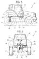
- figures 5 and 6, respectively, are side and front elevation views of an agricultural machine according to a second embodiment of the present invention.
- With reference to figures 1 to 4, 10 indicates an agricultural tractor comprising, in a conventional way, a pair of
front wheels 12 and a pair of therear wheels 14. Therear wheels 14 are rigidly connected to amain frame 16 whereas the front wheels are carried by a front axle (not shown) which normally is free to pivot about a longitudinal axis of the tractor. The front axle can also be connected to the frame by means of a suspension. - The tractor according to the present invention comprises a
cab 18 which is connected to themain frame 16 through a suspension system enabling a completely autonomous movement of the cab with respect to the frame, in order to ensure that the cab remains constantly horizontal for a certain range of terrain slope, both in transversal and longitudinal directions. Therefore, the operator constantly works with an horizontal cab, independently of the ground conditions. - In the embodiment shown in figures 1 to 4, the suspension system comprises four hydraulic or
pneumatic actuators 20 placed between thecab 18 and themain frame 16. Eachactuator 20 is connected to thecab 18 by means of a wide-strokeelastic support 26 which has the dual function of damping medium and high frequency vibrations produced both by the engine and the ground and to compensate angular tilt between thecab 18 and themain frame 16. - The
actuator 20 are controlled by avalve unit 22 which in its turn is controlled by anelectronic unit 24 placed into thecab 18. Theelectronic unit 24 is provided with sensors which detect the cab angular tilt. On the basis of information provided by such sensors, theelectronic unit 24 controls theactuators 20 for compensating the cab tilt, so that thecab 18 remains horizontal for any tilt both transversal and longitudinal, of themain frame 16 comprised in a predetermined range. - The sensors which detect the cab tilt may be:
- 1) either a biaxial inclinometer or two monoaxial inclinometers orthogonal to each other, plus either a biaxial turnmeter or two monoaxial turnmeters orthogonal to each other; or
- 2) either a biaxial gyroscope or a double monoaxial gyroscope; or
- 3) either a biaxial inclinometer or two monoaxial inclinometers orthogonal to each other, plus a sensor which detects the direction of the earth magnetic field; or
- 4) either a biaxial inclinometer or two monoaxial inclinometers orthogonal to each other, without turnmeter.
-
- The sensors indicated at points 1-3 enable a variation of the cab trim only as a function of actual tilts due to the terrain, without feeling the effects of either lateral acceleration (centrifugal acceleration during a turn) or longitudinal accelerations (acceleration generated during starting or breaking). The sensors described at point 4 are different from the preceding ones in that they are affected also by lateral and longitudinal accelerations. Therefore, while the sensors described at points 1-3 tend to maintain the cab horizontal in any situation, the sensors described at point 4 tend to maintain the resultant of accelerations always orthogonal to the cab floor and produce an undesired tilt of the cab when the tractor is subjected to transversal or longitudinal accelerations. Therefore, it is provided that the sensor described at point 4 can be used for an active control of the cab only when the tractor operates on a field and that they are not active when the tractor moves on a road. For example, the control system of the cab suspension could be automatically turned-off when the tractor exceeds a predetermined speed, for example of 10 Km/h.
- The
actuators 20 are preferably of a double-acting type and are rigidly anchored to themain frame 16 by means of support brackets schematically indicated at 28. Thevalve unit 22 comprises four on-off or proportional solenoid valves which control the movement of respective actuators. - This cab levelling system provides a real good comfort, absolutely non comparable with that of conventional cabs. This levelling system can be manually turned on or off. In addition, it could be provided with means for selecting either the levelling to be carried out in any direction or to compensating only transversal or longitudinal tilt angles. In addition, the
control unit 24 could be provided with a visual and acoustical alarm system for warning the operator of a roll over danger when the tilt angle of theframe 16 exceeds a danger value. This condition could be announced for example by the fact that one or more of the actuators has reached its end of stroke position. Finally, thecab 18 could be raised or lowered parallel to itself both for providing a better visibility in conditions wherein the tractor operates on level ground, and for improving accessibility between the cab and themain frame 16 during maintenance operations. - Figures 3 and 4 show schematically the way in which the
actuators 20 compensate longitudinal and transversal tilts. It will be understood that four actuators placed in correspondence with the cab corners can maintain the cab horizontal also in driving conditions wherein themain frame 16 has both a longitudinal and a transversal tilt. - In the variant shown in figures 5 and 6, the cab suspension system comprises two
rear actuators 30 and asingle front actuator 32 articulated to across beam 34 by means of aball joint 36. Thecross beam 34 is connected to thecab 18 by means of a pair ofelastic supports 38. Also this solution enables a contemporaneous compensation both of longitudinal and transversal inclinations, by virtue of the fact that thecross beam 34 can freely rotate about theball joint 36.
Claims (8)
- An agricultural machine, comprising:a pair of rear wheels (14), rigidly connected to a main frame (16), and a pair of front wheels (12) connected to the front wheels by means of a front axle,a control cab (18) mounted on the main frame (16), andsuspension means placed between the cab (18) and the main frame (16),
characterized in that said suspension means comprise a plurality of actuators (20; 30, 32) adapted to control the rotation of the cab (18) with respect to the main frame (16) about at least two axis orthogonal to each other, and in that the agricultural machine comprises an electronic control unit (24) provided with sensor means for detecting variations of the tilt angle of the cab (18) with respect to an horizontal reference direction, the electronic control unit (24) being programmed for controlling said actuators so as to maintain constant the orientation of the cab (18) with respect to said reference direction. - An agricultural machine according to claim 1, characterized in that said sensor means are not affected by variations of the cab tilt angle due to either transversal or longitudinal acceleration of the machine.
- An agricultural machine according to claim 1, characterized in that said electronic control unit (24) can be set out for compensating cab tilt angles only in a transversal direction or only in a longitudinal direction.
- An agricultural machine according to claim 1, characterized in that it comprises alarm means for announcing a tilt condition of the main frame (16) exceeding a predetermined safety threshold.
- An agricultural machine according to claim 1, characterized in that said sensor means are chosen in the group comprising:either a biaxial inclinometer or two monoaxial inclinometers orthogonal to each other, plus either a biaxial turnmeter or two monoaxial turnmeters;either a biaxial gyroscope or a double monoaxial gyroscope;either a biaxial inclinometer or two monoaxial inclinometers, plus a sensor which detects the direction of the earth magnetic field;either a biaxial inclinometer or two monoaxial inclinometers.
- An agricultural machine according to claim 1, characterized in that it comprises four linear actuators (20) placed in correspondence with the corners of the cab (18).
- An agricultural machine according to claim 1, characterized in that said suspension system comprises a pair of linear actuators (30) connected to the cab (18) by means of respective elastic supports (26) and a third linear actuator (32) articulated to a cross beam (34) by means of a ball joint (36), said cross beam (34) being connected to the cab (18) by means of a pair of elastic supports (38).
- An agricultural machine according to claim 1, characterized in that said suspension means (20; 30, 32) are adapted to raise or lower the cab parallel to itself, both for providing a better visibility in conditions in which the tractors operates on a level ground, and for improving accessibility between the cab (18) and the main frame (16) during maintenance operations.
Priority Applications (4)
| Application Number | Priority Date | Filing Date | Title |
|---|---|---|---|
| EP98830616A EP0994009B1 (en) | 1998-10-16 | 1998-10-16 | An agricultural machine with a self-leveling cab |
| DE69827946T DE69827946T2 (en) | 1998-10-16 | 1998-10-16 | Agricultural machine with self-aligning cab |
| CA002283134A CA2283134C (en) | 1998-10-16 | 1999-09-23 | An agricultural machine with a self-leveling cab |
| US09/419,329 US6273203B1 (en) | 1998-10-16 | 1999-10-15 | Agricultural machine with a self-leveling cab |
Applications Claiming Priority (1)
| Application Number | Priority Date | Filing Date | Title |
|---|---|---|---|
| EP98830616A EP0994009B1 (en) | 1998-10-16 | 1998-10-16 | An agricultural machine with a self-leveling cab |
Publications (2)
| Publication Number | Publication Date |
|---|---|
| EP0994009A1 true EP0994009A1 (en) | 2000-04-19 |
| EP0994009B1 EP0994009B1 (en) | 2004-12-01 |
Family
ID=8236837
Family Applications (1)
| Application Number | Title | Priority Date | Filing Date |
|---|---|---|---|
| EP98830616A Expired - Lifetime EP0994009B1 (en) | 1998-10-16 | 1998-10-16 | An agricultural machine with a self-leveling cab |
Country Status (4)
| Country | Link |
|---|---|
| US (1) | US6273203B1 (en) |
| EP (1) | EP0994009B1 (en) |
| CA (1) | CA2283134C (en) |
| DE (1) | DE69827946T2 (en) |
Cited By (12)
| Publication number | Priority date | Publication date | Assignee | Title |
|---|---|---|---|---|
| EP1584545A2 (en) | 2004-04-06 | 2005-10-12 | MAN Nutzfahrzeuge Aktiengesellschaft | Suspension for a driver cab of a utility vehicle and command process thereof |
| EP1593555A1 (en) * | 2004-03-16 | 2005-11-09 | Scania CV AB (publ) | Tilt alarm |
| EP1645494A2 (en) * | 2004-10-06 | 2006-04-12 | AGCO GmbH | Utility vehicle with suspended driver's cab |
| EP1661796A2 (en) | 2004-11-29 | 2006-05-31 | Renault Agriculture | Cabin suspension system |
| EP1702772A1 (en) * | 2005-03-18 | 2006-09-20 | MAN Nutzfahrzeuge Aktiengesellschaft | Arrangement and method for the height- control or regulation of the structure of a vehicle |
| EP1686045A3 (en) * | 2005-01-27 | 2007-08-15 | Hydac System GmbH | Self-propelled working machine |
| WO2010107749A1 (en) * | 2009-03-17 | 2010-09-23 | Clark Equipment Company | Operator compartment assembly for a work machine |
| EP2071420A3 (en) * | 2007-12-12 | 2012-06-06 | Volvo Construction Equipment Holding Sweden AB | Leveling control system and method for heavy equipment |
| US8655577B2 (en) | 2007-10-26 | 2014-02-18 | Wabco Gmbh | Device and method for automatically adjusting the horizontal ride level of a utility vehicle |
| CN107651026A (en) * | 2016-07-26 | 2018-02-02 | 曼卡车和巴士股份公司 | Method and apparatus for controlling or adjusting driver's cabin mounting seat |
| CN108974160A (en) * | 2018-06-20 | 2018-12-11 | 国网江苏省电力有限公司泰州供电分公司 | A kind of multifunction test tool car |
| IT201800003892A1 (en) * | 2018-03-22 | 2019-09-22 | Almac S R L | MOBILE LOADING PLATFORM |
Families Citing this family (31)
| Publication number | Priority date | Publication date | Assignee | Title |
|---|---|---|---|---|
| JP4535599B2 (en) * | 2000-11-01 | 2010-09-01 | 株式会社小松製作所 | Construction vehicle cab support device |
| US6923453B2 (en) * | 2001-05-29 | 2005-08-02 | Caterpillar Inc | Suspension leveling system |
| DE10232909A1 (en) | 2002-07-19 | 2004-01-29 | Deere & Company, Moline | Cabin storage for a vehicle cabin |
| GB0226843D0 (en) | 2002-11-16 | 2002-12-24 | Cnh Uk Ltd | cab support system for an agricultural vehicle |
| US7313472B2 (en) * | 2004-07-08 | 2007-12-25 | Deere & Company | Tractor power hop control system and method |
| US8180532B2 (en) * | 2006-05-26 | 2012-05-15 | Deere & Company | Vector controlled leveling system for a forestry machine |
| NZ574357A (en) * | 2006-07-31 | 2011-05-27 | Felix Edward Joseph Rust | Tilt apparatus comprising at least two inclination sensors providing continual slope information and relative tilted angle information |
| DE102007058694A1 (en) * | 2007-12-06 | 2009-06-10 | Jungheinrich Ag | Three-wheeled vehicle, in particular industrial truck with tilt protection |
| US9254728B2 (en) | 2008-05-15 | 2016-02-09 | Oxbo International Corporation | Suspension system with a floating axle lock |
| US8196936B2 (en) * | 2008-06-11 | 2012-06-12 | Elworth Cheek | Independent suspension for lawnmowers, cutting decks and off-road vehicles |
| US20100204886A1 (en) * | 2009-02-12 | 2010-08-12 | Lockheed Martin Corporation | Method and system for increasing a vehicle side slope operating capabilities |
| ITTO20090139A1 (en) | 2009-02-26 | 2010-08-27 | Cnh Italia Spa | AGRICULTURAL VEHICLE |
| JP5115655B2 (en) * | 2009-05-18 | 2013-01-09 | トヨタ自動車株式会社 | Vehicle control device |
| US8807633B2 (en) | 2011-06-21 | 2014-08-19 | Cnh Industrial America Llc | Cab suspension system for an off-road vehicle |
| SE1251057A1 (en) * | 2012-09-20 | 2014-03-21 | Scania Cv Ab | Procedure and system for level control of vehicle configuration |
| US9200429B2 (en) | 2013-10-31 | 2015-12-01 | Deere & Company | Work vehicle with loader controlled cab tilting |
| DK3059104T3 (en) * | 2015-02-18 | 2018-12-10 | Eco Log Sweden Ab | A HYDRAULIC CYLINDER DEVICE, SPRING DEVICE AND CONTROL DEVICE FOR SHOCK, NOISE AND VIBRATION-ABSORBING SPRING OF A CABIN |
| DE102015122777B4 (en) * | 2015-12-23 | 2023-02-02 | Grammer Aktiengesellschaft | Suspension device and method |
| US10040327B2 (en) | 2016-05-10 | 2018-08-07 | Deere & Company | Oscillation control system and method |
| US10525784B2 (en) * | 2016-06-29 | 2020-01-07 | Upnride Robotics Ltd. | Self-leveling mechanism and method for wheeled mobility device |
| US10730359B2 (en) | 2017-12-11 | 2020-08-04 | Cnh Industrial America Llc | Suspension control system providing suspension height corrections for an agricultural machine |
| US10569612B2 (en) | 2017-12-11 | 2020-02-25 | Cnh Industrial America Llc | Suspension control system providing tire height corrections for an agricultural machine |
| US10436622B2 (en) | 2017-12-11 | 2019-10-08 | Cnh Industrial America Llc | Suspension control system providing closed loop control of hydraulic fluid volumes for an agricultural machine |
| US10183542B1 (en) | 2017-12-11 | 2019-01-22 | Cnh Industrial America Llc | Suspension control system providing orientation control for an agricultural machine |
| FI128126B (en) | 2017-12-29 | 2019-10-15 | Ponsse Oyj | Arrangement and method for levelling the cabin of a work machine |
| DE102017012140A1 (en) * | 2017-12-30 | 2019-07-04 | Hydac Systems & Services Gmbh | Device for vibration decoupling between two systems and work machine |
| GB2628708A (en) | 2021-07-27 | 2024-10-02 | Caterpillar Inc | Telehandler and Method |
| US11959249B2 (en) | 2021-09-14 | 2024-04-16 | Caterpillar Global Mining Equipment Llc | System and method for automatic tilting of operator cabin |
| CN114132397A (en) * | 2021-11-25 | 2022-03-04 | 扬州神舟汽车内饰件有限公司 | Intelligent engineering truck cab |
| CN114228845A (en) * | 2021-11-30 | 2022-03-25 | 江苏徐工工程机械研究院有限公司 | Suspension device, control method thereof, vehicle and engineering machinery |
| CN114516370A (en) * | 2022-03-03 | 2022-05-20 | 马春生 | Transverse balancing system capable of being carried on various vehicle platforms |
Citations (9)
| Publication number | Priority date | Publication date | Assignee | Title |
|---|---|---|---|---|
| US3703298A (en) * | 1970-07-06 | 1972-11-21 | Laverda Spa Pietro | Device for automatic self-levelling of the body of a threshing-harvesting machine |
| US3917295A (en) * | 1973-06-30 | 1975-11-04 | Nissan Motor | Fluid operated vehicle body level control system |
| US4440093A (en) * | 1980-06-23 | 1984-04-03 | Hitachi, Ltd. | Vehicle tilt control apparatus |
| JPH0194007A (en) * | 1987-10-02 | 1989-04-12 | Komatsu Ltd | Automatic horizontal control mechanism for vehicle and the like |
| FR2640206A1 (en) * | 1988-12-09 | 1990-06-15 | Bringuier Jean Marc | Vehicle of the "all terrain" type for filming |
| JPH03186485A (en) * | 1989-12-16 | 1991-08-14 | Kubota Corp | Attitude control device for working vehicle |
| US5337847A (en) * | 1993-01-15 | 1994-08-16 | Risley Fluidic Power Ltd. | Four-way levelling mechanism for off-road vehicle |
| JPH07276958A (en) * | 1994-04-15 | 1995-10-24 | Toyota Autom Loom Works Ltd | Vehicle attitude control method and device |
| US5684698A (en) * | 1994-04-15 | 1997-11-04 | Kabushiki Kaisha Toyoda Jidoshokki Seisakusho | Vehicle attitude and average height control apparatus |
Family Cites Families (2)
| Publication number | Priority date | Publication date | Assignee | Title |
|---|---|---|---|---|
| JPH07156837A (en) * | 1993-12-09 | 1995-06-20 | Isuzu Motors Ltd | Hydraulic suspension device of cab |
| US5941920A (en) * | 1997-11-12 | 1999-08-24 | Case Corporation | Control of an active suspension system for a work vehicle based upon a parameter of another vehicle system |
-
1998
- 1998-10-16 DE DE69827946T patent/DE69827946T2/en not_active Expired - Fee Related
- 1998-10-16 EP EP98830616A patent/EP0994009B1/en not_active Expired - Lifetime
-
1999
- 1999-09-23 CA CA002283134A patent/CA2283134C/en not_active Expired - Fee Related
- 1999-10-15 US US09/419,329 patent/US6273203B1/en not_active Expired - Fee Related
Patent Citations (9)
| Publication number | Priority date | Publication date | Assignee | Title |
|---|---|---|---|---|
| US3703298A (en) * | 1970-07-06 | 1972-11-21 | Laverda Spa Pietro | Device for automatic self-levelling of the body of a threshing-harvesting machine |
| US3917295A (en) * | 1973-06-30 | 1975-11-04 | Nissan Motor | Fluid operated vehicle body level control system |
| US4440093A (en) * | 1980-06-23 | 1984-04-03 | Hitachi, Ltd. | Vehicle tilt control apparatus |
| JPH0194007A (en) * | 1987-10-02 | 1989-04-12 | Komatsu Ltd | Automatic horizontal control mechanism for vehicle and the like |
| FR2640206A1 (en) * | 1988-12-09 | 1990-06-15 | Bringuier Jean Marc | Vehicle of the "all terrain" type for filming |
| JPH03186485A (en) * | 1989-12-16 | 1991-08-14 | Kubota Corp | Attitude control device for working vehicle |
| US5337847A (en) * | 1993-01-15 | 1994-08-16 | Risley Fluidic Power Ltd. | Four-way levelling mechanism for off-road vehicle |
| JPH07276958A (en) * | 1994-04-15 | 1995-10-24 | Toyota Autom Loom Works Ltd | Vehicle attitude control method and device |
| US5684698A (en) * | 1994-04-15 | 1997-11-04 | Kabushiki Kaisha Toyoda Jidoshokki Seisakusho | Vehicle attitude and average height control apparatus |
Non-Patent Citations (3)
| Title |
|---|
| PATENT ABSTRACTS OF JAPAN vol. 013, no. 305 (M - 849) 13 July 1989 (1989-07-13) * |
| PATENT ABSTRACTS OF JAPAN vol. 015, no. 441 (M - 1177) 11 November 1991 (1991-11-11) * |
| PATENT ABSTRACTS OF JAPAN vol. 096, no. 002 29 February 1996 (1996-02-29) * |
Cited By (19)
| Publication number | Priority date | Publication date | Assignee | Title |
|---|---|---|---|---|
| EP1593555A1 (en) * | 2004-03-16 | 2005-11-09 | Scania CV AB (publ) | Tilt alarm |
| EP1584545A3 (en) * | 2004-04-06 | 2006-09-27 | MAN Nutzfahrzeuge Aktiengesellschaft | Suspension for a driver cab of a utility vehicle and command process thereof |
| DE102004016910B4 (en) | 2004-04-06 | 2019-05-23 | Man Truck & Bus Ag | Suspension for a cab of a commercial vehicle and method for its control |
| EP1584545A2 (en) | 2004-04-06 | 2005-10-12 | MAN Nutzfahrzeuge Aktiengesellschaft | Suspension for a driver cab of a utility vehicle and command process thereof |
| EP1700777A1 (en) * | 2004-04-06 | 2006-09-13 | MAN Nutzfahrzeuge Aktiengesellschaft | Suspension for a driver cab of a utility vehicle and command process thereof |
| EP1645494A3 (en) * | 2004-10-06 | 2008-01-16 | AGCO GmbH | Utility vehicle with suspended driver's cab |
| EP1645494A2 (en) * | 2004-10-06 | 2006-04-12 | AGCO GmbH | Utility vehicle with suspended driver's cab |
| EP1661796A2 (en) | 2004-11-29 | 2006-05-31 | Renault Agriculture | Cabin suspension system |
| EP1661796A3 (en) * | 2004-11-29 | 2011-01-05 | CLAAS Tractor SAS | Cabin suspension system |
| EP1686045A3 (en) * | 2005-01-27 | 2007-08-15 | Hydac System GmbH | Self-propelled working machine |
| EP1702772A1 (en) * | 2005-03-18 | 2006-09-20 | MAN Nutzfahrzeuge Aktiengesellschaft | Arrangement and method for the height- control or regulation of the structure of a vehicle |
| US8655577B2 (en) | 2007-10-26 | 2014-02-18 | Wabco Gmbh | Device and method for automatically adjusting the horizontal ride level of a utility vehicle |
| EP2071420A3 (en) * | 2007-12-12 | 2012-06-06 | Volvo Construction Equipment Holding Sweden AB | Leveling control system and method for heavy equipment |
| WO2010107749A1 (en) * | 2009-03-17 | 2010-09-23 | Clark Equipment Company | Operator compartment assembly for a work machine |
| US7946370B2 (en) | 2009-03-17 | 2011-05-24 | Clark Equipment Company | Operator compartment assembly |
| CN107651026A (en) * | 2016-07-26 | 2018-02-02 | 曼卡车和巴士股份公司 | Method and apparatus for controlling or adjusting driver's cabin mounting seat |
| CN107651026B (en) * | 2016-07-26 | 2021-10-15 | 曼卡车和巴士股份公司 | Method and device for controlling or adjusting a cab mount |
| IT201800003892A1 (en) * | 2018-03-22 | 2019-09-22 | Almac S R L | MOBILE LOADING PLATFORM |
| CN108974160A (en) * | 2018-06-20 | 2018-12-11 | 国网江苏省电力有限公司泰州供电分公司 | A kind of multifunction test tool car |
Also Published As
| Publication number | Publication date |
|---|---|
| DE69827946D1 (en) | 2005-01-05 |
| DE69827946T2 (en) | 2005-12-29 |
| EP0994009B1 (en) | 2004-12-01 |
| US6273203B1 (en) | 2001-08-14 |
| CA2283134C (en) | 2004-12-28 |
| CA2283134A1 (en) | 2000-04-16 |
Similar Documents
| Publication | Publication Date | Title |
|---|---|---|
| CA2283134C (en) | An agricultural machine with a self-leveling cab | |
| US10245984B2 (en) | Seat system for a vehicle | |
| US6923453B2 (en) | Suspension leveling system | |
| US4580797A (en) | Device at cross-country vehicles or machines | |
| AU2010241344A1 (en) | Cab suspension for a swather tractor | |
| US11317555B2 (en) | Work vehicle | |
| EP0882641B1 (en) | Agricultural vehicle with cab and cab suspension | |
| JPH0799812A (en) | Horizontal control device for rice transplanter | |
| EP0636512A1 (en) | Seat foundation | |
| JP2558754B2 (en) | Walk-type paddy work machine | |
| JP3838320B2 (en) | Horizontal control device | |
| GB2388826A (en) | A vehicle with a body part or cab which is adjustable in longitudunal inclination | |
| JPH0132808Y2 (en) | ||
| JPS6026724B2 (en) | agricultural tractor | |
| JP3511081B2 (en) | Transplant machine | |
| JPH0513125Y2 (en) | ||
| JP2507939B2 (en) | Rolling control device for agricultural machinery | |
| JPH0352185Y2 (en) | ||
| JPH0559750A (en) | Traveling vehicle fitted with liftable working machine | |
| JP3720506B2 (en) | Farm work vehicle | |
| JPH07241102A (en) | Apparatus for controlling posture of working machine of farm tractor | |
| JP2575004B2 (en) | Walking paddy working machine | |
| JP3785827B2 (en) | Tractor lifting control device | |
| JPH03276889A (en) | Height control unit for crawler body gravitational center | |
| JP2018166440A (en) | Agricultural machine |
Legal Events
| Date | Code | Title | Description |
|---|---|---|---|
| PUAI | Public reference made under article 153(3) epc to a published international application that has entered the european phase |
Free format text: ORIGINAL CODE: 0009012 |
|
| AK | Designated contracting states |
Kind code of ref document: A1 Designated state(s): DE FR GB IT |
|
| AX | Request for extension of the european patent |
Free format text: AL;LT;LV;MK;RO;SI |
|
| AKX | Designation fees paid |
Free format text: DE FR GB IT |
|
| 17P | Request for examination filed |
Effective date: 19990723 |
|
| 17Q | First examination report despatched |
Effective date: 20010830 |
|
| RAP1 | Party data changed (applicant data changed or rights of an application transferred) |
Owner name: SAME DEUTZ-FAHR GROUP SPA |
|
| GRAP | Despatch of communication of intention to grant a patent |
Free format text: ORIGINAL CODE: EPIDOSNIGR1 |
|
| GRAS | Grant fee paid |
Free format text: ORIGINAL CODE: EPIDOSNIGR3 |
|
| GRAA | (expected) grant |
Free format text: ORIGINAL CODE: 0009210 |
|
| AK | Designated contracting states |
Kind code of ref document: B1 Designated state(s): DE FR GB IT |
|
| REG | Reference to a national code |
Ref country code: GB Ref legal event code: FG4D |
|
| REF | Corresponds to: |
Ref document number: 69827946 Country of ref document: DE Date of ref document: 20050105 Kind code of ref document: P |
|
| ET | Fr: translation filed | ||
| PLBE | No opposition filed within time limit |
Free format text: ORIGINAL CODE: 0009261 |
|
| STAA | Information on the status of an ep patent application or granted ep patent |
Free format text: STATUS: NO OPPOSITION FILED WITHIN TIME LIMIT |
|
| PG25 | Lapsed in a contracting state [announced via postgrant information from national office to epo] |
Ref country code: IT Free format text: LAPSE BECAUSE OF NON-PAYMENT OF DUE FEES;WARNING: LAPSES OF ITALIAN PATENTS WITH EFFECTIVE DATE BEFORE 2007 MAY HAVE OCCURRED AT ANY TIME BEFORE 2007. THE CORRECT EFFECTIVE DATE MAY BE DIFFERENT FROM THE ONE RECORDED. Effective date: 20051016 Ref country code: GB Free format text: LAPSE BECAUSE OF NON-PAYMENT OF DUE FEES Effective date: 20051016 |
|
| 26N | No opposition filed |
Effective date: 20050902 |
|
| PG25 | Lapsed in a contracting state [announced via postgrant information from national office to epo] |
Ref country code: DE Free format text: LAPSE BECAUSE OF NON-PAYMENT OF DUE FEES Effective date: 20060503 |
|
| GBPC | Gb: european patent ceased through non-payment of renewal fee |
Effective date: 20051016 |
|
| PG25 | Lapsed in a contracting state [announced via postgrant information from national office to epo] |
Ref country code: FR Free format text: LAPSE BECAUSE OF NON-PAYMENT OF DUE FEES Effective date: 20060630 |
|
| REG | Reference to a national code |
Ref country code: FR Ref legal event code: ST Effective date: 20060630 |