EP1584509A2 - Roller blind for sliding roof system - Google Patents
Roller blind for sliding roof system Download PDFInfo
- Publication number
- EP1584509A2 EP1584509A2 EP04025215A EP04025215A EP1584509A2 EP 1584509 A2 EP1584509 A2 EP 1584509A2 EP 04025215 A EP04025215 A EP 04025215A EP 04025215 A EP04025215 A EP 04025215A EP 1584509 A2 EP1584509 A2 EP 1584509A2
- Authority
- EP
- European Patent Office
- Prior art keywords
- roller blind
- blind
- guide rails
- spiral
- coil springs
- Prior art date
- Legal status (The legal status is an assumption and is not a legal conclusion. Google has not performed a legal analysis and makes no representation as to the accuracy of the status listed.)
- Granted
Links
Images


Classifications
-
- B—PERFORMING OPERATIONS; TRANSPORTING
- B60—VEHICLES IN GENERAL
- B60J—WINDOWS, WINDSCREENS, NON-FIXED ROOFS, DOORS, OR SIMILAR DEVICES FOR VEHICLES; REMOVABLE EXTERNAL PROTECTIVE COVERINGS SPECIALLY ADAPTED FOR VEHICLES
- B60J7/00—Non-fixed roofs; Roofs with movable panels, e.g. rotary sunroofs
- B60J7/0007—Non-fixed roofs; Roofs with movable panels, e.g. rotary sunroofs moveable head-liners, screens, curtains or blinds for ceilings
- B60J7/0015—Non-fixed roofs; Roofs with movable panels, e.g. rotary sunroofs moveable head-liners, screens, curtains or blinds for ceilings roller blind
Definitions
- the invention relates to a roller blind for a sunroof system.
- Such a roller blind may be below an opening in a vehicle roof be attached to the opening more or less as desired by the vehicle occupants less cover. If the opening is to be released, the roller blind is on a winding axle wound by a spring in the winding direction is charged. From the winding axis, the roller blind against the force of Spring are withdrawn so that it covers the opening. So that the blind, if it is located below the opening in the vehicle roof, not in the Vehicle interior sags into it, the longitudinal edges of the roller blind are each in taken a guide rail, so that it is transverse to the direction of displacement can be kept tense.
- the object of the invention is to provide a roller blind, which with low effort on the one hand can be wound reliably, on the other hand remains reliable in every position. In addition, it should have a low construction and space requirements can be realized.
- the invention provides that the blind consists of a flexible material, wherein two coil springs are provided, extending along the longitudinal edges of the roller blind and become a spiral looking to contract.
- the invention is based on the basic idea instead of a force acting on the winding axis spring two coil springs use, which act directly on the roller blind itself. This way will the part of the blind that is not in the guide rails automatically rolled up into a wrap. In this way affects the part of the Roller blinds, which is located in the guide rails, only a very low traction one.
- the bias of the coil springs causes them within the Guide rails generate a relatively high friction. This prevents reliable, that the blind adjusted by itself in an undesirable manner.
- the coil springs at the same time for leadership serve the blinds in a guide rail.
- the otherwise elements used to guide the roller blind e.g. Keder, edge bead or Guide bar, be waived.
- the Spiral springs are biased so that when they are outside the Guide rails are located and there is no roller blind between them, each would contract into a spiral whose tips from each other are averted. This ensures that the generated by the coil springs Rollowickel is kept taut across the guide rails, though is dispensed with a winding axis.
- the invention also relates to an assembly consisting of a roller blind, the its longitudinal edges are each provided with a spiral spring, and two Guide rails, in which the corresponding coil spring is received, so that the roller blind is guided between the guide rails, wherein the part of the Spiral springs, which is located outside the guide rails, together with the attached roller blind by itself wound into a roll.
- a vehicle roof 5 can be seen, which with an opening. 7 is provided.
- the opening 7 is a cover 9 of a sliding roof system assigned.
- the lid 9 can between a closed position, in which it closes the opening 7, and an open position shown in Figure 1 be adjusted.
- Below the lid 9 and also below the opening 7 is a roller blind 10 is arranged.
- the blind 10 can, based on the vehicle, after be moved front and back. When the shade 10 is completely back is pushed, the opening 7 is fully released. Fresh air and Sunlight then has free access to the vehicle interior. When the roller blind 10 is pushed completely forward, the opening 7 is covered by the roller blind. Fresh air and sunlight can thus only to a limited extent in the Get inside the vehicle.
- the roller blind 10 is made of a flexible material, such as fabric or a plastic film. At its front edge a bow 12 is provided at a vehicle occupant can attack to the blind to the front or back to move. Laterally along the opening 7 extend two Guide rails 14, in which the two longitudinal edges of the roller blind, ie in the Vehicle longitudinal direction considered the right and left edges of the curtain 10, are included. In the region of the rear end of the opening 7 is located the rear edge of the roller blind, on which a winding body 16 is mounted. Of the Winding body is not stored on the roof; he can run as a plastic strip be splashed on the rear edge of the roller blind and essentially the Function has the rear edge of the roller blind in a direction transverse to the Keep stretched longitudinally of the vehicle.
- a coil spring 18 is provided in each case, as thin metal strip is formed from spring plate and as a guide element serves.
- the coil spring 18 has, when in the corresponding guide rail is recorded, the visible in Figure 3, curved cross-sectional shape.
- the Roller blind 10 is connected to the coil springs 18 only on the outer half, so from the outer edge to about the apex of the coil springs 18. This Range is indicated in Figure 3 by the reference numeral 20.
- the roller blind 10 can be glued to the coil spring 18 in particular.
- the guide rail 14 has a generally rectangular in section Cross-section, in the interior of the coil spring 18 together with the at her attached edge portion of the blind 10 is attached.
- the guide rail On the to the vehicle center directed side, the guide rail has a leg 22 which is between the roller blind 10 and the vehicle center directed portion of the coil spring 18th engages, ie in the area in which the blind 10 is not with the coil spring 18 is glued. The coil spring 18 can thereby below the leg supported to keep the shade 10 in the transverse direction stretched.
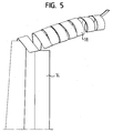
- the two coil springs 18 are biased so that they are self-acting roll up. Furthermore, they are so biased that they roll up "diagonally" try, as can be seen in Figure 5.
- Each coil spring 18 would, if they are can roll up freely and no roller blind 10 and no bobbin 16 would be present roll up so that a spiral is created, whose free end points outwards, ie away from the other spiral spring. This ensures that the roller blind 10 between the two coil springs when they are outside the guide rails 14th are held tightly taut.
- the coil springs 18 change their cross-sectional shape of the in 3 in a second cross-sectional shape shown in FIG Figure 4 is shown.
- the coil springs have a flat, rectangular Cross section whose height corresponds to the material thickness of the coil springs 18. Therefore results in a winding with a small diameter.
Abstract
Description
Die Erfindung betrifft ein Rollo für ein Schiebedachsystem.The invention relates to a roller blind for a sunroof system.
Ein solches Rollo kann unterhalb einer Öffnung in einem Fahrzeugdach angebracht sein, um die Öffnung je nach Wunsch der Fahrzeuginsassen mehr oder weniger abzudecken. Wenn die Öffnung freigegeben sein soll, ist das Rollo auf einer Wickelachse aufgewickelt, die von einer Feder in der Aufwickelrichtung beaufschlagt wird. Von der Wickelachse kann das Rollo entgegen der Kraft der Feder abgezogen werden, so daß es die Öffnung abdeckt. Damit das Rollo, wenn es sich unterhalb der Öffnung im Fahrzeugdach befindet, nicht in den Fahrzeuginnenraum hinein durchhängt, sind die Längsränder des Rollos jeweils in einer Führungsschiene aufgenommen, so daß es quer zur Verschieberichtung gespannt gehalten werden kann.Such a roller blind may be below an opening in a vehicle roof be attached to the opening more or less as desired by the vehicle occupants less cover. If the opening is to be released, the roller blind is on a winding axle wound by a spring in the winding direction is charged. From the winding axis, the roller blind against the force of Spring are withdrawn so that it covers the opening. So that the blind, if it is located below the opening in the vehicle roof, not in the Vehicle interior sags into it, the longitudinal edges of the roller blind are each in taken a guide rail, so that it is transverse to the direction of displacement can be kept tense.
Nachteilig bei den bekannten Rollos ist, daß die auf die Wickelachse wirkende Feder stark genug sein muß, um das Rollo zuverlässig aufwickeln zu können, gleichzeitig aber die Feder das Rollo, wenn das Rollo vom Benutzer in eine gewünschte Stellung gebracht wurde, nicht von alleine verstellen darf. Im Hinblick auf die Alterung der Feder und die unterschiedlichen Reibungsverhältnisse, die über die Lebensdauer des Rollos auftreten können, sowie die verschiedenen Federkräfte, die bei vollständig von der Wickelachse abgezogenem Rollo einerseits und nahezu vollständig aufgewickeltem Rollo andererseits wirken, lassen sich die beiden Anforderungen nur mit großem Aufwand erfüllen.A disadvantage of the known roller blinds that acting on the winding axis Spring must be strong enough to wind the blind reliably, at the same time, however, the spring the roller blind when the roller blind by the user in one desired position was brought, may not adjust by itself. in the With regard to the aging of the spring and the different ones Friction conditions that can occur over the life of the roller blind, as well as the various spring forces when completely off the winding axis pulled blind on the one hand and almost completely wound up blind On the other hand, the two requirements can be met only with great Effort to meet.
Die Aufgabe der Erfindung besteht darin, ein Rollo zu schaffen, welches mit geringem Aufwand einerseits zuverlässig aufgewickelt werden kann, andererseits in jeder Stellung zuverlässig verbleibt. Außerdem soll es mit einem geringen Bau- und Platzbedarf realisiert werden können.The object of the invention is to provide a roller blind, which with low effort on the one hand can be wound reliably, on the other hand remains reliable in every position. In addition, it should have a low construction and space requirements can be realized.
Zur Lösung dieser Aufgabe ist erfindungsgemäß vorgesehen, daß das Rollo aus einem flexiblen Material besteht, wobei zwei Spiralfedern vorgesehen sind, die sich entlang den Längsrändern des Rollos erstrecken und sich zu einer Spirale zusammenzuziehen suchen. Die Erfindung beruht auf dem Grundgedanken, anstelle einer auf die Wickelachse einwirkenden Feder zwei Spiralfedern zu verwenden, die unmittelbar auf das Rollo selbst einwirken. Auf diese Weise wird der Teil des Rollos, der sich nicht in den Führungsschienen befindet, automatisch zu einem Wickel zusammengerollt. Auf diese Weise wirkt auf den Teil des Rollos, der sich in den Führungsschienen befindet, nur eine sehr geringe Zugkraft ein. Außerdem führt die Vorspannung der Spiralfedern dazu, daß sie innerhalb der Führungsschienen eine vergleichsweise hohe Reibung erzeugen. Dies verhindert zuverlässig, daß sich das Rollo von allein in unerwünschter Weise verstellt. Auf eine separate Rollobremse kann verzichtet werden. Schließlich ergibt sich ein geringerer Bauraum, da keine die Wickelachse beaufschlagende Feder notwendig ist, oder es kann auf die Wickelachse vollständig verzichtet werden, so daß sich das Rollo frei aufwickelt, sobald es die Führungsschienen verlassen hat.To solve this problem, the invention provides that the blind consists of a flexible material, wherein two coil springs are provided, extending along the longitudinal edges of the roller blind and become a spiral looking to contract. The invention is based on the basic idea instead of a force acting on the winding axis spring two coil springs use, which act directly on the roller blind itself. This way will the part of the blind that is not in the guide rails automatically rolled up into a wrap. In this way affects the part of the Roller blinds, which is located in the guide rails, only a very low traction one. In addition, the bias of the coil springs causes them within the Guide rails generate a relatively high friction. This prevents reliable, that the blind adjusted by itself in an undesirable manner. On a separate roller brake can be dispensed with. Finally, a result less space, since no spring acting on the winding axis necessary is, or it can be completely dispensed with the winding axis, so that The roller blind unwinds as soon as it has left the guide rails.
Vorzugsweise ist vorgesehen, daß die Spiralfedern gleichzeitig zur Führung des Rollos in einer Führungsschiene dienen. Auf diese Weise kann auf die sonst zur Führung des Rollos verwendeten Elemente, z.B. Keder, Randwulst oder Führungsleiste, verzichtet werden.It is preferably provided that the coil springs at the same time for leadership serve the blinds in a guide rail. In this way can on the otherwise elements used to guide the roller blind, e.g. Keder, edge bead or Guide bar, be waived.
Gemäß einer bevorzugten Ausführungsform ist vorgesehen, daß die Spiralfedern so vorgespannt sind, daß sie, wenn sie sich außerhalb der Führungsschienen befinden und kein Rollo zwischen ihnen vorhanden wäre, jeweils zu einer Spirale zusammenziehen würden, deren Spitzen voneinander abgewandt sind. Dies gewährleistet, daß der von den Spiralfedern erzeugte Rollowickel quer zu den Führungsschienen straff gespannt gehalten wird, wenn auf eine Wickelachse verzichtet wird.According to a preferred embodiment it is provided that the Spiral springs are biased so that when they are outside the Guide rails are located and there is no roller blind between them, each would contract into a spiral whose tips from each other are averted. This ensures that the generated by the coil springs Rollowickel is kept taut across the guide rails, though is dispensed with a winding axis.
Die Erfindung betrifft auch eine Baugruppe bestehend aus einem Rollo, das an seinen Längsrändern mit jeweils einer Spiralfeder versehen ist, und zwei Führungsschienen, in denen die entsprechende Spiralfeder aufgenommen ist, so daß das Rollo zwischen den Führungsschienen geführt ist, wobei sich der Teil der Spiralfedern, der sich außerhalb der Führungsschienen befindet, zusammen mit dem daran angebrachten Rollo von allein zu einem Wickel aufwickelt. Hinsichtlich der Vorteile wird auf die obigen Erläuterungen verwiesen.The invention also relates to an assembly consisting of a roller blind, the its longitudinal edges are each provided with a spiral spring, and two Guide rails, in which the corresponding coil spring is received, so that the roller blind is guided between the guide rails, wherein the part of the Spiral springs, which is located outside the guide rails, together with the attached roller blind by itself wound into a roll. With regard to the advantages, reference is made to the above explanations.
Die Erfindung wird nachfolgend anhand einer bevorzugten Ausführungsform beschrieben, die in den beigefügten Zeichnungen dargestellt ist. In diesen zeigen:
- Figur 1 eine perspektivische Ansicht eines Fahrzeugdaches mit einem erfindungsgemäßen Rollo;
- Figur 2 eine schematische Seitenansicht eines erfindungsgemäßen Rollos;
- Figur 3 einen Schnitt entlang der Ebene III-III von Figur 1;
- Figur 4 in vergrößertem Maßstab den Ausschnitt IV von Figur 2; und
- Figur 5 in einer schematischen Ansicht eine Spiralfeder in einem Zustand, den sie einnimmt, wenn keine äußeren Kräfte einwirken.
- Figure 1 is a perspective view of a vehicle roof with a roller blind according to the invention;
- Figure 2 is a schematic side view of a roller blind according to the invention;
- Figure 3 is a section along the plane III-III of Figure 1;
- Figure 4 on an enlarged scale the detail IV of Figure 2; and
- Figure 5 is a schematic view of a coil spring in a state which it assumes when no external forces act.
In Figur 1 ist ein Fahrzeugdach 5 zu sehen, welches mit einer Öffnung 7
versehen ist. Der Öffnung 7 ist ein Deckel 9 eines Schiebedachsystems
zugeordnet. Der Deckel 9 kann zwischen einer geschlossenen Stellung, in welcher
er die Öffnung 7 verschließt, und einer in Figur 1 gezeigten, geöffneten Stellung
verstellt werden. Unterhalb des Deckels 9 und auch unterhalb der Öffnung 7 ist
ein Rollo 10 angeordnet. Das Rollo 10 kann, bezogen auf das Fahrzeug, nach
vorne und hinten verschoben werden. Wenn das Rollo 10 vollständig nach hinten
geschoben ist, ist die Öffnung 7 vollständig freigegeben. Frischluft und
Sonnenlicht haben dann freien Zugang zum Fahrzeuginnenraum. Wenn das Rollo
10 vollständig nach vorne geschoben ist, ist die Öffnung 7 vom Rollo abgedeckt.
Frischluft und Sonnenlicht können somit nur in begrenztem Umfang in den
Fahrzeuginnenraum gelangen.In Figure 1, a vehicle roof 5 can be seen, which with an opening. 7
is provided. The opening 7 is a cover 9 of a sliding roof system
assigned. The lid 9 can between a closed position, in which
it closes the opening 7, and an open position shown in Figure 1
be adjusted. Below the lid 9 and also below the opening 7 is
a roller blind 10 is arranged. The blind 10 can, based on the vehicle, after
be moved front and back. When the
Das Rollo 10 besteht aus einem flexiblen Material, beispielsweise Stoff oder
einer Kunststofffolie. An seinem vorderen Rand ist ein Spriegel 12 vorgesehen, an
dem ein Fahrzeuginsasse angreifen kann, um das Rollo nach vorne oder hinten zu
verschieben. Seitlich entlang der Öffnung 7 erstrecken sich zwei
Führungsschienen 14, in denen die beiden Längsränder des Rollos, also in der
Fahrzeuglängsrichtung betrachtet der rechte und der linke Rand des Rollos 10,
aufgenommen sind. Im Bereich des hinteren Endes der Öffnung 7 befindet sich
der hintere Rand des Rollos, an dem ein Wickelkörper 16 angebracht ist. Der
Wickelkörper ist nicht am Dach gelagert; er kann als Kunststoffleiste ausgeführt
sein, die auf den hinteren Rand des Rollos aufgespritzt ist und im wesentlichen die
Funktion hat, den hinteren Rand des Rollos in einer Richtung quer zur
Längsrichtung des Fahrzeugs gespannt zu halten.The roller blind 10 is made of a flexible material, such as fabric or
a plastic film. At its front edge a
Entlang den Längsrändern des Rollos 10, also in dem den Führungsschienen
14 zugeordneten Bereich, ist jeweils eine Spiralfeder 18 vorgesehen, die als
dünner Metallstreifen aus Federblech ausgebildet ist und als Führungselement
dient. Die Spiralfeder 18 hat, wenn sie in der entsprechenden Führungsschiene
aufgenommen ist, die in Figur 3 sichtbare, gekrümmte Querschnittsform. Das
Rollo 10 ist mit den Spiralfedern 18 nur auf deren äußerer Hälfte verbunden, also
vom außenliegenden Rand bis etwa zum Scheitelpunkt der Spiralfedern 18. Dieser
Bereich ist in Figur 3 mit dem Bezugszeichen 20 bezeichnet. Das Rollo 10 kann
mit der Spiralfeder 18 insbesondere verklebt sein.Along the longitudinal edges of the roller blind 10, ie in the
Die Führungsschiene 14 hat im Schnitt einen allgemein rechteckigen
Querschnitt, in dessen Innenraum die Spiralfeder 18 zusammen mit dem an ihr
angebrachten Randabschnitt des Rollos 10 befestigt ist. Auf der zur Fahrzeugmitte
gerichteten Seite weist die Führungsschiene einen Schenkel 22 auf, der zwischen
das Rollo 10 und den zur Fahrzeugmitte gerichteten Abschnitt der Spiralfeder 18
eingreift, also in den Bereich, in welchem das Rollo 10 nicht mit der Spiralfeder
18 verklebt ist. Die Spiralfeder 18 kann sich dadurch unterhalb des Schenkels
abstützen, um das Rollo 10 in Querrichtung gespannt zu halten.The
Die beiden Spiralfedern 18 sind so vorgespannt, daß sie sich selbsttätig
aufrollen. Weiterhin sind sie so vorgespannt, daß sie sich "schräg" aufzurollen
versuchen, wie in Figur 5 zu sehen ist. Jeder Spiralfeder 18 würde, wenn sie sich
frei aufrollen kann und kein Rollo 10 und kein Wickelkörper 16 vorhanden wäre,
so aufrollen, daß eine Spirale entsteht, deren freies Ende nach außen zeigt, also
von der anderen Spiralfeder weg. Dies gewährleistet, daß das Rollo 10 zwischen
den beiden Spiralfedern, wenn diese sich außerhalb der Führungsschienen 14
befinden, straff gespannt gehalten wird.The two
Wenn das Rollo 10 nach hinten verschoben wird, um die Öffnung 7
freizugeben, wird der hintere Bereich des Rollos 10 aus den Führungsschienen 14
herausgeschoben. Dabei wird es von den Spiralfedern 18 automatisch und von
alleine zu einem Wickel aufgerollt. Dieser ist aufgrund der Vorspannung der
Spiralfedern und aufgrund des Wickelkörpers 16 straff gespannt. Der Rollowickel
liegt an einer Wand 24 an, die einen Aufnahmeraum für das aufgewickelte Rollo
10 abgrenzt.When the
Da keine Feder vorhanden ist, die auf das Rollo eine von der Stellung des Rollos abhängige Aufwickelkraft ausübt, ergibt sich eine konstante Zugkraft, die einer Verstellung des Rollos nach vorne entgegenwirkt. Ein weiterer Effekt ist eine Erhöhung der Verschiebekraft, so daß man darüber eine Selbsthemmung erhält. Somit bleibt ein von Hand betätigtes Rollo in jeder Zwischenposition stehen, ohne daß eine zusätzliche Rollobremse notwendig istSince there is no spring on the roller blind one of the position of the Roller blind dependent winder force, results in a constant tensile force, the an adjustment of the blinds counteracts forward. Another effect is an increase in the displacement force, so that it is a self-locking receives. Thus, a manually operated roller blind remains in any intermediate position stand, without an additional roller brake is necessary
Wenn das Rollo 10 die Führungsschienen 14 verläßt und zu einem Wickel
aufgewickelt wird, ändern die Spiralfedern 18 ihre Querschnittsform aus der in
Figur 3 gezeigten ersten Querschnittsform in eine zweite Querschnittsform, die in
Figur 4 gezeigt ist. Die Spiralfedern haben einen flachen, rechteckigen
Querschnitt, dessen Höhe der Materialdicke der Spiralfedern 18 entspricht. Daher
ergibt sich eine Wickel mit einem geringen Durchmesser. When the
- 55
- Fahrzeugdachvehicle roof
- 77
- Öffnungopening
- 99
- Deckelcover
- 1010
- Rolloroller blind
- 1212
- SpriegelSpriegel
- 1414
- Führungsschieneguide rail
- 1616
- Wickelkörperbobbin
- 1818
- Führungselementguide element
- 2020
- Verbindungsbereichconnecting area
- 2222
- Schenkelleg
- 2424
- Wandwall
Claims (5)
Priority Applications (1)
| Application Number | Priority Date | Filing Date | Title |
|---|---|---|---|
| KR1020050029026A KR20060045574A (en) | 2004-04-08 | 2005-04-07 | Window blind for a sliding roof system |
Applications Claiming Priority (2)
| Application Number | Priority Date | Filing Date | Title |
|---|---|---|---|
| DE102004017459A DE102004017459A1 (en) | 2004-04-08 | 2004-04-08 | Roller blind for a sunroof system |
| DE102004017459 | 2004-04-08 |
Publications (3)
| Publication Number | Publication Date |
|---|---|
| EP1584509A2 true EP1584509A2 (en) | 2005-10-12 |
| EP1584509A3 EP1584509A3 (en) | 2007-10-17 |
| EP1584509B1 EP1584509B1 (en) | 2013-04-03 |
Family
ID=34895536
Family Applications (2)
| Application Number | Title | Priority Date | Filing Date |
|---|---|---|---|
| EP04025215A Revoked EP1584509B1 (en) | 2004-04-08 | 2004-10-22 | Roller blind for sliding roof system |
| EP04025214.0A Active EP1588880B2 (en) | 2004-04-08 | 2004-10-22 | Roller blind for sliding roof assembly |
Family Applications After (1)
| Application Number | Title | Priority Date | Filing Date |
|---|---|---|---|
| EP04025214.0A Active EP1588880B2 (en) | 2004-04-08 | 2004-10-22 | Roller blind for sliding roof assembly |
Country Status (5)
| Country | Link |
|---|---|
| US (2) | US7114767B2 (en) |
| EP (2) | EP1584509B1 (en) |
| KR (1) | KR20060045572A (en) |
| CN (2) | CN1680127B (en) |
| DE (1) | DE102004017459A1 (en) |
Cited By (8)
| Publication number | Priority date | Publication date | Assignee | Title |
|---|---|---|---|---|
| WO2007118455A3 (en) * | 2006-04-13 | 2007-12-27 | Webasto Ag | Blind assembly for a vehicle |
| EP1900560A1 (en) * | 2006-09-13 | 2008-03-19 | ArvinMeritor GmbH | Sun blind system for sunroof |
| DE102006057273A1 (en) * | 2006-11-23 | 2008-05-29 | Bos Gmbh & Co. Kg | Protective device for load holding space of motor vehicle has return device with spring band, the length of which corresponds approximately to length of partitioning net as seen in extension direction |
| DE102007021049A1 (en) | 2007-05-04 | 2008-11-13 | Webasto Ag | Roller blind device, in particular for a sunroof system |
| EP1992511A2 (en) * | 2007-05-04 | 2008-11-19 | Webasto AG | Roller blind device, in particular for a sliding roof system |
| EP2529965A1 (en) | 2011-06-01 | 2012-12-05 | Roof Systems Germany GmbH | Roller blind for a sliding roof system |
| US9387748B2 (en) | 2013-03-26 | 2016-07-12 | Aisin Seiki Kabushiki Kaisha | Roll shade apparatus for vehicle |
| DE102019103081A1 (en) * | 2019-02-07 | 2020-08-13 | Webasto SE | Method for producing a textile module for a roller blind |
Families Citing this family (41)
| Publication number | Priority date | Publication date | Assignee | Title |
|---|---|---|---|---|
| DE102005024657C5 (en) * | 2004-11-19 | 2016-04-21 | Webasto Ag | Roller blind arrangement for a vehicle |
| DE102005048207B3 (en) * | 2005-10-07 | 2006-11-23 | Webasto Ag | Roller blind fitting for motor vehicle includes side winding guide in region of winding shaft for each guide band |
| DE102006023370A1 (en) * | 2006-05-16 | 2007-11-22 | Brose Fahrzeugteile Gmbh & Co. Kommanditgesellschaft, Coburg | Roller blind for motor vehicles |
| EP1908616B1 (en) * | 2006-10-06 | 2013-04-17 | Inalfa Roof Systems Group B.V. | Sunshade assembly and open roof construction provided therewith |
| DE102006062542A1 (en) | 2006-12-29 | 2008-07-03 | Webasto Ag | Shading device for installation under roof of vehicle, has covering element including reinforcement strips and adjustable between closing or covering position and opening position at laminar extensions of covering element at lateral guides |
| EP1953018B1 (en) * | 2007-01-31 | 2010-03-17 | ArvinMeritor GmbH | Guiding system for a roller blind of a sliding roof system |
| DE102007041298B4 (en) * | 2007-08-31 | 2010-06-10 | Webasto Ag | Roller blind arrangement for a motor vehicle |
| DE102007047758B4 (en) * | 2007-09-28 | 2009-07-23 | Bos Gmbh & Co. Kg | Protective device for a vehicle interior |
| DE102008008941B4 (en) | 2008-02-13 | 2023-10-12 | PS : DESIGN+PRODUCTS GmbH | Sun protection system with a windable curtain |
| DE212008000124U1 (en) | 2008-08-27 | 2011-05-26 | Inalfa Roof Systems Group B.V. | Sun visor assembly and thus provided open roof construction |
| US8316736B2 (en) * | 2008-10-06 | 2012-11-27 | Honda Motor Co., Ltd. | Steering column cover |
| WO2010063312A1 (en) | 2008-12-02 | 2010-06-10 | Inalfa Roof Systems Group B.V. | Sunshade assembly and open roof construction provided therewith |
| JP5458695B2 (en) † | 2009-06-29 | 2014-04-02 | アイシン精機株式会社 | Roll shade device |
| EP2338716B1 (en) | 2009-12-23 | 2012-11-21 | Inalfa Roof Systems Group B.V. | Sunshade assembly and open roof construction provided therewith |
| DE102010008766C5 (en) * | 2010-02-22 | 2014-04-17 | Webasto SE | Roller blind arrangement for a motor vehicle |
| JP2011230705A (en) † | 2010-04-28 | 2011-11-17 | Toyota Motor Corp | Shade apparatus for vehicle |
| DE102011010568B4 (en) * | 2011-02-07 | 2013-07-18 | Michael Heidan | Roof system for a vehicle with a heating element |
| CN102180121A (en) * | 2011-04-18 | 2011-09-14 | 南车眉山车辆有限公司 | Carriage head cover sealing system |
| JP2012240500A (en) * | 2011-05-17 | 2012-12-10 | Aisin Seiki Co Ltd | Roller shade apparatus for vehicle |
| DE102011113207B4 (en) | 2011-09-08 | 2014-07-03 | Webasto Ag | Vehicle blind arrangement and vehicle roof |
| TW201331062A (en) * | 2012-01-19 | 2013-08-01 | Macauto Ind Co Ltd | Spiral spring type sunroof shading blind |
| JP5993593B2 (en) * | 2012-03-21 | 2016-09-14 | 八千代工業株式会社 | Sunshade equipment |
| JP5989378B2 (en) * | 2012-04-04 | 2016-09-07 | ベバスト ジャパン株式会社 | Roll shade device |
| JP6250917B2 (en) * | 2012-04-04 | 2017-12-20 | ベバスト ジャパン株式会社 | Roll shade device |
| JP6118642B2 (en) | 2013-05-31 | 2017-04-19 | ベバスト ジャパン株式会社 | Roll shade device |
| JP5713077B2 (en) * | 2013-10-04 | 2015-05-07 | アイシン精機株式会社 | Roll shade device |
| US10216066B2 (en) | 2013-10-24 | 2019-02-26 | Stephen Pilby | Flexible light control grid with collapsible frame |
| DE102014002961A1 (en) * | 2014-03-06 | 2015-09-24 | Roof Systems Germany Gmbh | Roller blind system for a sunroof |
| EP3017985B1 (en) | 2014-11-06 | 2021-01-27 | Inalfa Roof Systems Group B.V. | Sunshade assembly and respective flexible sunscreen |
| EP3064386B1 (en) | 2015-03-04 | 2020-02-12 | Inalfa Roof Systems Group B.V. | Sunshade assembly and open roof construction provided therewith |
| EP3109080B1 (en) * | 2015-06-22 | 2018-09-19 | Inalfa Roof Systems Group B.V. | Sunshade assembly and open roof construction provided therewith |
| BR112018014365B1 (en) * | 2016-01-13 | 2024-01-02 | Cornellcookson, Llc | ROLL-UP DOORS, ROLL-UP DOOR ASSEMBLY AND METHOD FOR ATTACHING THEM TO A GUIDE |
| EP3222452B1 (en) | 2016-03-21 | 2020-05-27 | Inalfa Roof Systems Group B.V. | Sliding support arrangement and roof assembly for a vehicle |
| CN105818655B (en) * | 2016-04-26 | 2019-12-31 | 昆山隆泰汽车配件有限公司 | Automatic turn-ups anticreep formula sunroof sunshade screen |
| CN109153318B (en) * | 2016-05-31 | 2022-07-08 | 英纳法天窗系统集团有限公司 | Open roof construction for a vehicle and roller blind assembly for use therein |
| DE102017129328B4 (en) * | 2017-12-08 | 2023-02-02 | Roof Systems Germany Gmbh | Sun blind system for a motor vehicle |
| EP3711989B1 (en) | 2019-03-20 | 2023-08-16 | Inalfa Roof Systems Group B.V. | Sunscreen and sunshade system for use in a vehicle roof assembly |
| WO2020252253A1 (en) | 2019-06-12 | 2020-12-17 | Shanghai Yanfeng Jinqiao Automotive Trim Systems Co. Ltd. | Vehicle component |
| JP7153165B2 (en) * | 2020-04-02 | 2022-10-13 | 八千代工業株式会社 | Shade guide structure |
| CN112193033A (en) * | 2020-10-16 | 2021-01-08 | 北京汽车集团越野车有限公司 | Waterproof curtain assembly and vehicle |
| EP4187039A1 (en) | 2021-11-26 | 2023-05-31 | Gluetex GmbH | Flat article assembly |
Citations (3)
| Publication number | Priority date | Publication date | Assignee | Title |
|---|---|---|---|---|
| FR1467839A (en) | 1965-12-16 | 1967-02-03 | Griesser & Cie | Device for guiding blinds in guides |
| GB1416431A (en) | 1972-02-08 | 1975-12-03 | Hawker Siddeley Aviation Ltd | Window blinds especially for aircraft passenger cabins |
| US4825921A (en) | 1986-05-07 | 1989-05-02 | Rigter Steven M | Blinds, screens, partitions and doors |
Family Cites Families (19)
| Publication number | Priority date | Publication date | Assignee | Title |
|---|---|---|---|---|
| US1882982A (en) † | 1930-11-25 | 1932-10-18 | August J Schmiedeskamp | Rolling screen retaining means |
| US2874770A (en) † | 1955-07-15 | 1959-02-24 | Gen Motors Corp | Self-supporting blind |
| DE1401266A1 (en) † | 1958-11-21 | 1968-10-24 | Tigrett John B | Spring ribbon wound into a spiral |
| GB1304727A (en) † | 1970-09-15 | 1973-01-31 | ||
| US4707018A (en) * | 1986-02-07 | 1987-11-17 | Irvin Industries, Inc. | Free standing sunshade assembly |
| DE4202342C1 (en) † | 1992-01-29 | 1993-03-18 | Mercedes-Benz Aktiengesellschaft, 7000 Stuttgart, De | Roller blind for motor car windows - has strip of material wound on rod with cross-strip attached to end of material and can be force down against spiral springs |
| US6309076B1 (en) † | 1994-12-29 | 2001-10-30 | Mcvicker Richard E. | Light barrier, screen or reflector |
| CN2251504Y (en) * | 1995-10-13 | 1997-04-09 | 周小祥 | Sunshading and ventilating curtain for car |
| FR2741658B1 (en) * | 1995-11-29 | 1999-02-26 | Farnier Et Penin Snc | TRIM AND INSULATION BLIND FOR SUNROOF VEHICLE |
| DE19739919C2 (en) † | 1997-09-11 | 1999-07-08 | Rockwell International Gmbh | Sun blind for a motor vehicle roof |
| US6047762A (en) † | 1998-03-20 | 2000-04-11 | Prince Corporation | Shade control for a vehicle window |
| CN2409077Y (en) * | 1999-12-21 | 2000-12-06 | 萧世理 | Improved automobile curtain rail |
| DE10019644B4 (en) * | 2000-04-19 | 2004-09-09 | Webasto Vehicle Systems International Gmbh | Sun protection device for a vehicle |
| DE10140412C1 (en) † | 2001-08-23 | 2002-11-14 | Daimler Chrysler Ag | Roller blind, for screening automobile window, has roller blind web provided with spring bands for providing stability |
| DE10216186A1 (en) † | 2002-04-04 | 2003-10-16 | Brose Fahrzeugteile | Sun protection roller blind for windows in motor vehicles has roller length of self-supporting material and tension cable between blind layers, to eliminate need for side guide rails |
| DE10225360C1 (en) * | 2002-06-06 | 2003-10-23 | Webasto Vehicle Sys Int Gmbh | Roller blind, as a motor vehicle sun blind, has openings in the edges to form tabs which are moved upwards around the side guide rails to hold the edges in place when unwound |
| FR2841204B1 (en) * | 2002-06-21 | 2005-01-14 | Webasto Systemes Carrosserie | PAVILION MODULE FOR MOTOR VEHICLE |
| DE10253816B3 (en) † | 2002-11-18 | 2004-02-05 | Webasto Vehicle Systems International Gmbh | Roller blind device for vehicle has holding elements in form of grip elements fixed to side edge of roller blind |
| DE20309690U1 (en) † | 2003-06-24 | 2003-09-11 | Kuhlemann Horst | Roller blind for side window of road vehicle has housing containing winding spring housings, electric motor and winding spindle for blind |
-
2004
- 2004-04-08 DE DE102004017459A patent/DE102004017459A1/en not_active Ceased
- 2004-10-22 EP EP04025215A patent/EP1584509B1/en not_active Revoked
- 2004-10-22 EP EP04025214.0A patent/EP1588880B2/en active Active
- 2004-10-25 US US10/973,081 patent/US7114767B2/en active Active
- 2004-10-25 CN CN2004100877132A patent/CN1680127B/en active Active
- 2004-10-25 CN CN2004100877170A patent/CN1680128B/en not_active Ceased
- 2004-10-25 US US10/973,080 patent/US7114766B2/en active Active
-
2005
- 2005-04-07 KR KR1020050029021A patent/KR20060045572A/en not_active Application Discontinuation
Patent Citations (3)
| Publication number | Priority date | Publication date | Assignee | Title |
|---|---|---|---|---|
| FR1467839A (en) | 1965-12-16 | 1967-02-03 | Griesser & Cie | Device for guiding blinds in guides |
| GB1416431A (en) | 1972-02-08 | 1975-12-03 | Hawker Siddeley Aviation Ltd | Window blinds especially for aircraft passenger cabins |
| US4825921A (en) | 1986-05-07 | 1989-05-02 | Rigter Steven M | Blinds, screens, partitions and doors |
Cited By (15)
| Publication number | Priority date | Publication date | Assignee | Title |
|---|---|---|---|---|
| WO2007118455A3 (en) * | 2006-04-13 | 2007-12-27 | Webasto Ag | Blind assembly for a vehicle |
| US9038699B2 (en) | 2006-04-13 | 2015-05-26 | Webasto SE | Blind assembly for a vehicle |
| US7530630B2 (en) | 2006-09-13 | 2009-05-12 | Arvinmeritor Technology, Llc | Roller blind system for a sliding roof |
| EP1900560A1 (en) * | 2006-09-13 | 2008-03-19 | ArvinMeritor GmbH | Sun blind system for sunroof |
| DE102006057273A1 (en) * | 2006-11-23 | 2008-05-29 | Bos Gmbh & Co. Kg | Protective device for load holding space of motor vehicle has return device with spring band, the length of which corresponds approximately to length of partitioning net as seen in extension direction |
| DE102007021049A1 (en) | 2007-05-04 | 2008-11-13 | Webasto Ag | Roller blind device, in particular for a sunroof system |
| EP1992511A3 (en) * | 2007-05-04 | 2008-12-24 | Webasto AG | Roller blind device, in particular for a sliding roof system |
| WO2008135018A3 (en) * | 2007-05-04 | 2009-02-12 | Webasto Ag | Blind device, particularly for a sunroof system |
| WO2009033439A1 (en) * | 2007-05-04 | 2009-03-19 | Webasto Ag | Roller blind device, particularly for a sliding roof system |
| EP1992511A2 (en) * | 2007-05-04 | 2008-11-19 | Webasto AG | Roller blind device, in particular for a sliding roof system |
| US8430148B2 (en) | 2007-05-04 | 2013-04-30 | Webasto SE | Roller blind device |
| WO2008135018A2 (en) * | 2007-05-04 | 2008-11-13 | Webasto Ag | Blind device, particularly for a sunroof system |
| EP2529965A1 (en) | 2011-06-01 | 2012-12-05 | Roof Systems Germany GmbH | Roller blind for a sliding roof system |
| US9387748B2 (en) | 2013-03-26 | 2016-07-12 | Aisin Seiki Kabushiki Kaisha | Roll shade apparatus for vehicle |
| DE102019103081A1 (en) * | 2019-02-07 | 2020-08-13 | Webasto SE | Method for producing a textile module for a roller blind |
Also Published As
| Publication number | Publication date |
|---|---|
| EP1588880A2 (en) | 2005-10-26 |
| US20050225122A1 (en) | 2005-10-13 |
| US7114766B2 (en) | 2006-10-03 |
| CN1680128B (en) | 2010-09-15 |
| EP1588880B1 (en) | 2013-03-20 |
| CN1680128A (en) | 2005-10-12 |
| KR20060045572A (en) | 2006-05-17 |
| EP1584509B1 (en) | 2013-04-03 |
| CN1680127B (en) | 2010-04-28 |
| EP1588880B2 (en) | 2018-09-19 |
| EP1584509A3 (en) | 2007-10-17 |
| US7114767B2 (en) | 2006-10-03 |
| CN1680127A (en) | 2005-10-12 |
| EP1588880A3 (en) | 2007-10-17 |
| DE102004017459A1 (en) | 2005-10-27 |
| US20050225123A1 (en) | 2005-10-13 |
Similar Documents
| Publication | Publication Date | Title |
|---|---|---|
| EP1584509B1 (en) | Roller blind for sliding roof system | |
| DE19739919C2 (en) | Sun blind for a motor vehicle roof | |
| EP1006012B1 (en) | Roller blind for vehicle | |
| EP1953018B1 (en) | Guiding system for a roller blind of a sliding roof system | |
| EP1900560B1 (en) | Sun blind system for sunroof | |
| DE102007041298A1 (en) | Roller blind arrangement for a motor vehicle | |
| EP2039547A2 (en) | Side window blind with intake aid | |
| EP1495888A1 (en) | Sunshade for vehicle roof | |
| DE212008000124U1 (en) | Sun visor assembly and thus provided open roof construction | |
| EP1393939A2 (en) | Roller blind for solar protection | |
| DE202005006415U1 (en) | Roller blind assembly for a vehicle roof has a wind-up aid arranged behind a guide for guiding the blind during winding out so that it engages with spiral springs during winding and unwinding | |
| DE102017101017B4 (en) | SUN PROTECTION ROLLER WITH ROPE FOR A VEHICLE DISK | |
| WO2018114343A1 (en) | Blind device on a vehicle roof | |
| DE202006003831U1 (en) | Roller blind for a motor vehicle's sunroof system has spiral springs along its edges, a winding body and an adhesive layer for fastening the roller blind on the winding body | |
| EP2949492B1 (en) | Sliding canvas cover for with secure cover tensioning profile | |
| DE102007021049B4 (en) | Roller blind device, in particular for a sunroof system | |
| DE102008008941A1 (en) | Sun protection system with a windable curtain | |
| DE19903212B4 (en) | Device for rolling up and rolling out a tarpaulin | |
| DE202004015857U1 (en) | Sun blind, for an automobile glass roof, has one end anchored at a winding shaft and tubes along the longitudinal side edges to ride over side guide rods using non-stick materials | |
| DE202004020095U1 (en) | Automotive sunscreen blind is deployed by hand from upright cassette along guide rails | |
| DE102017101018A1 (en) | SUNSHIELD ROLL WITH PARTIAL CLOSED FLAP WITH EXTENDED CABLE | |
| DE102007019741A1 (en) | Roller blind for interior roof lining of motor vehicle, has upper and lower bearings formed of windable material, where shape and/or optical appearance of lower bearing is determined and/or adjusted in unwound condition | |
| DE102010042829A1 (en) | Shadowing system for covering upper portion of window opening in e.g. driver door of motor car, has guide rail including gap to guide sheet upper edge area and designed so that area sectionally projects through gap into rail in use position | |
| DE10316785A1 (en) | Roller blind has blinds that overlap at edges and/or are adjacent with no gaps with blinds wound in; spooling shafts associated with blind tracks are mutually offset when viewed in winding direction | |
| DE102020108874A1 (en) | Darkening device for a motor vehicle, vehicle roof and motor vehicle |
Legal Events
| Date | Code | Title | Description |
|---|---|---|---|
| PUAI | Public reference made under article 153(3) epc to a published international application that has entered the european phase |
Free format text: ORIGINAL CODE: 0009012 |
|
| AK | Designated contracting states |
Kind code of ref document: A2 Designated state(s): AT BE BG CH CY CZ DE DK EE ES FI FR GB GR HU IE IT LI LU MC NL PL PT RO SE SI SK TR |
|
| AX | Request for extension of the european patent |
Extension state: AL HR LT LV MK |
|
| PUAL | Search report despatched |
Free format text: ORIGINAL CODE: 0009013 |
|
| AK | Designated contracting states |
Kind code of ref document: A3 Designated state(s): AT BE BG CH CY CZ DE DK EE ES FI FR GB GR HU IE IT LI LU MC NL PL PT RO SE SI SK TR |
|
| AX | Request for extension of the european patent |
Extension state: AL HR LT LV MK |
|
| 17P | Request for examination filed |
Effective date: 20080318 |
|
| AKX | Designation fees paid |
Designated state(s): DE FR NL |
|
| TPAC | Observations by third parties |
Free format text: ORIGINAL CODE: EPIDOSNTIPA |
|
| 17Q | First examination report despatched |
Effective date: 20090730 |
|
| RAP1 | Party data changed (applicant data changed or rights of an application transferred) |
Owner name: ROOF SYSTEMS GERMANY GMBH |
|
| GRAP | Despatch of communication of intention to grant a patent |
Free format text: ORIGINAL CODE: EPIDOSNIGR1 |
|
| GRAS | Grant fee paid |
Free format text: ORIGINAL CODE: EPIDOSNIGR3 |
|
| GRAA | (expected) grant |
Free format text: ORIGINAL CODE: 0009210 |
|
| AK | Designated contracting states |
Kind code of ref document: B1 Designated state(s): DE FR NL |
|
| REG | Reference to a national code |
Ref country code: DE Ref legal event code: R096 Ref document number: 502004014091 Country of ref document: DE Effective date: 20130606 |
|
| REG | Reference to a national code |
Ref country code: NL Ref legal event code: T3 |
|
| PLBI | Opposition filed |
Free format text: ORIGINAL CODE: 0009260 |
|
| PLBI | Opposition filed |
Free format text: ORIGINAL CODE: 0009260 |
|
| 26 | Opposition filed |
Opponent name: BOS GMBH & CO. KG Effective date: 20131218 |
|
| PLAX | Notice of opposition and request to file observation + time limit sent |
Free format text: ORIGINAL CODE: EPIDOSNOBS2 |
|
| 26 | Opposition filed |
Opponent name: ADVANCED COMFORT SYSTEMS FRANCE SAS-ACS FRANCE Effective date: 20140103 Opponent name: WEBASTO SE Effective date: 20131227 |
|
| REG | Reference to a national code |
Ref country code: DE Ref legal event code: R026 Ref document number: 502004014091 Country of ref document: DE Effective date: 20131218 |
|
| PLAF | Information modified related to communication of a notice of opposition and request to file observations + time limit |
Free format text: ORIGINAL CODE: EPIDOSCOBS2 |
|
| PLBB | Reply of patent proprietor to notice(s) of opposition received |
Free format text: ORIGINAL CODE: EPIDOSNOBS3 |
|
| PLAB | Opposition data, opponent's data or that of the opponent's representative modified |
Free format text: ORIGINAL CODE: 0009299OPPO |
|
| R26 | Opposition filed (corrected) |
Opponent name: ADVANCED COMFORT SYSTEMS FRANCE SAS-ACS FRANCE Effective date: 20140103 |
|
| APBM | Appeal reference recorded |
Free format text: ORIGINAL CODE: EPIDOSNREFNO |
|
| APBP | Date of receipt of notice of appeal recorded |
Free format text: ORIGINAL CODE: EPIDOSNNOA2O |
|
| APAH | Appeal reference modified |
Free format text: ORIGINAL CODE: EPIDOSCREFNO |
|
| REG | Reference to a national code |
Ref country code: FR Ref legal event code: PLFP Year of fee payment: 12 |
|
| APBM | Appeal reference recorded |
Free format text: ORIGINAL CODE: EPIDOSNREFNO |
|
| APBP | Date of receipt of notice of appeal recorded |
Free format text: ORIGINAL CODE: EPIDOSNNOA2O |
|
| APBQ | Date of receipt of statement of grounds of appeal recorded |
Free format text: ORIGINAL CODE: EPIDOSNNOA3O |
|
| APBQ | Date of receipt of statement of grounds of appeal recorded |
Free format text: ORIGINAL CODE: EPIDOSNNOA3O |
|
| REG | Reference to a national code |
Ref country code: FR Ref legal event code: PLFP Year of fee payment: 13 |
|
| REG | Reference to a national code |
Ref country code: FR Ref legal event code: PLFP Year of fee payment: 14 |
|
| PGFP | Annual fee paid to national office [announced via postgrant information from national office to epo] |
Ref country code: FR Payment date: 20170918 Year of fee payment: 14 |
|
| PGFP | Annual fee paid to national office [announced via postgrant information from national office to epo] |
Ref country code: DE Payment date: 20171018 Year of fee payment: 14 |
|
| PGFP | Annual fee paid to national office [announced via postgrant information from national office to epo] |
Ref country code: NL Payment date: 20171016 Year of fee payment: 14 |
|
| REG | Reference to a national code |
Ref country code: DE Ref legal event code: R064 Ref document number: 502004014091 Country of ref document: DE Ref country code: DE Ref legal event code: R103 Ref document number: 502004014091 Country of ref document: DE |
|
| APBU | Appeal procedure closed |
Free format text: ORIGINAL CODE: EPIDOSNNOA9O |
|
| RDAF | Communication despatched that patent is revoked |
Free format text: ORIGINAL CODE: EPIDOSNREV1 |
|
| RDAG | Patent revoked |
Free format text: ORIGINAL CODE: 0009271 |
|
| STAA | Information on the status of an ep patent application or granted ep patent |
Free format text: STATUS: PATENT REVOKED |
|
| 27W | Patent revoked |
Effective date: 20180309 |