JP7153165B2 - Shade guide structure - Google Patents
Shade guide structure Download PDFInfo
- Publication number
- JP7153165B2 JP7153165B2 JP2022511685A JP2022511685A JP7153165B2 JP 7153165 B2 JP7153165 B2 JP 7153165B2 JP 2022511685 A JP2022511685 A JP 2022511685A JP 2022511685 A JP2022511685 A JP 2022511685A JP 7153165 B2 JP7153165 B2 JP 7153165B2
- Authority
- JP
- Japan
- Prior art keywords
- guide
- shade
- band
- shade sheet
- sheet
- Prior art date
- Legal status (The legal status is an assumption and is not a legal conclusion. Google has not performed a legal analysis and makes no representation as to the accuracy of the status listed.)
- Active
Links
Images


Classifications
-
- E—FIXED CONSTRUCTIONS
- E06—DOORS, WINDOWS, SHUTTERS, OR ROLLER BLINDS IN GENERAL; LADDERS
- E06B—FIXED OR MOVABLE CLOSURES FOR OPENINGS IN BUILDINGS, VEHICLES, FENCES OR LIKE ENCLOSURES IN GENERAL, e.g. DOORS, WINDOWS, BLINDS, GATES
- E06B9/00—Screening or protective devices for wall or similar openings, with or without operating or securing mechanisms; Closures of similar construction
- E06B9/24—Screens or other constructions affording protection against light, especially against sunshine; Similar screens for privacy or appearance; Slat blinds
- E06B9/40—Roller blinds
- E06B9/42—Parts or details of roller blinds, e.g. suspension devices, blind boxes
-
- B—PERFORMING OPERATIONS; TRANSPORTING
- B60—VEHICLES IN GENERAL
- B60J—WINDOWS, WINDSCREENS, NON-FIXED ROOFS, DOORS, OR SIMILAR DEVICES FOR VEHICLES; REMOVABLE EXTERNAL PROTECTIVE COVERINGS SPECIALLY ADAPTED FOR VEHICLES
- B60J1/00—Windows; Windscreens; Accessories therefor
- B60J1/20—Accessories, e.g. wind deflectors, blinds
- B60J1/2011—Blinds; curtains or screens reducing heat or light intensity
- B60J1/2013—Roller blinds
- B60J1/2036—Roller blinds characterised by structural elements
- B60J1/2041—Blind sheets, e.g. shape of sheets, reinforcements in sheets, materials therefor
-
- B—PERFORMING OPERATIONS; TRANSPORTING
- B60—VEHICLES IN GENERAL
- B60J—WINDOWS, WINDSCREENS, NON-FIXED ROOFS, DOORS, OR SIMILAR DEVICES FOR VEHICLES; REMOVABLE EXTERNAL PROTECTIVE COVERINGS SPECIALLY ADAPTED FOR VEHICLES
- B60J1/00—Windows; Windscreens; Accessories therefor
- B60J1/20—Accessories, e.g. wind deflectors, blinds
- B60J1/2011—Blinds; curtains or screens reducing heat or light intensity
- B60J1/2013—Roller blinds
- B60J1/2036—Roller blinds characterised by structural elements
- B60J1/2052—Guides
-
- E—FIXED CONSTRUCTIONS
- E06—DOORS, WINDOWS, SHUTTERS, OR ROLLER BLINDS IN GENERAL; LADDERS
- E06B—FIXED OR MOVABLE CLOSURES FOR OPENINGS IN BUILDINGS, VEHICLES, FENCES OR LIKE ENCLOSURES IN GENERAL, e.g. DOORS, WINDOWS, BLINDS, GATES
- E06B9/00—Screening or protective devices for wall or similar openings, with or without operating or securing mechanisms; Closures of similar construction
- E06B9/56—Operating, guiding or securing devices or arrangements for roll-type closures; Spring drums; Tape drums; Counterweighting arrangements therefor
- E06B9/58—Guiding devices
- E06B9/581—Means to prevent or induce disengagement of shutter from side rails
-
- E—FIXED CONSTRUCTIONS
- E06—DOORS, WINDOWS, SHUTTERS, OR ROLLER BLINDS IN GENERAL; LADDERS
- E06B—FIXED OR MOVABLE CLOSURES FOR OPENINGS IN BUILDINGS, VEHICLES, FENCES OR LIKE ENCLOSURES IN GENERAL, e.g. DOORS, WINDOWS, BLINDS, GATES
- E06B9/00—Screening or protective devices for wall or similar openings, with or without operating or securing mechanisms; Closures of similar construction
- E06B9/56—Operating, guiding or securing devices or arrangements for roll-type closures; Spring drums; Tape drums; Counterweighting arrangements therefor
- E06B9/58—Guiding devices
- E06B9/582—Means to increase gliss, light, sound or thermal insulation
Description
本開示は、シェードシートをガイドするシェードガイド構造に関する。 The present disclosure relates to a shade guide structure that guides a shade sheet.
ルーフ用のブラインド(シェード)として、巻取軸に巻き付けられた可撓性材料からなるブラインドシートを有し、ブラインドシートが巻取軸から引き出された展開状態においてブラインドシートを張設状態に保持するロールブラインド(ロールシェード)がある。この種のブラインドでは、ブラインドシートの引き出し方向の端縁に幅方向に延在するバー(ハンドル)が取り付けられ、バーの長手方向の両端部はガイドレールに案内される。ブラインドシートの両側縁には、ブラインドシートの垂れ下がりを防止するために、ガイドレールに案内されるガイド要素が設けられる。ガイド要素はブラインドシートと共に巻取軸に巻き取られる。このようなガイド要素を介してブラインドシートをガイドする様々なガイド構造が提案されている。 A blind (shade) for a roof has a blind sheet made of a flexible material wound around a winding shaft, and holds the blind sheet in a stretched state in an unfolded state in which the blind sheet is pulled out from the winding shaft. There are roll blinds (roll shades). In this type of blind, a bar (handle) extending in the width direction is attached to the edge of the blind sheet in the pull-out direction, and both longitudinal ends of the bar are guided by guide rails. Both side edges of the blind sheet are provided with guide elements guided on guide rails in order to prevent the blind sheet from sagging. The guide element is wound up on the winding shaft together with the blind sheet. Various guide structures have been proposed for guiding the blind sheet through such guide elements.
特許文献1の図12等には、サンロールブラインドの側縁に上下に延出するガイド要素が設けられ、このガイド要素がガイドレールに形成された縦長の溝内でガイドされる構成が開示されている。
FIG. 12 of
特許文献2の図3には、ブラインドの側縁部に平坦なストリップであるガイド要素が固定され、ガイド要素が上向きに凸に湾曲した断面形状を有し、ガイド要素の略頂点にブラインドが接続される形態が開示されている。また、同文献の図5には、ガイド要素が平らな長方形の断面を有し、傾斜した姿勢でガイド溝に配置され、ガイド要素の上側部分にブラインドが接続され、ガイド要素の下側部分が脚部により支持される形態が開示されている。
In FIG. 3 of
特許文献3の図14には、上方に開放した出口隙間(スロット)を有する横長断面形状の案内通路に案内帯が配置された構成が開示されている。案内帯のブラインドシートが縫い付けられた位置から内側のエッジまでの寸法は、スロットの内側の側面から案内通路の内側面までの寸法よりも大きくされている。これにより、ブラインドシートの擦り切れ防止が図られている。
FIG. 14 of
特許文献4には、遮光シートの側縁に取り付けられた可撓ベルト(案内帯)が上又は下に凸に湾曲した円弧形状の断面を有し、遮光シートの面に沿って横長な湾曲形状のベルトガイド部に収容される構成が開示されている。ベルトガイド部は、可撓ベルトの両側部を係止する1対の係止部を備え、これにより遮光シートから引張応力が加わっても、応力が両係止部に著しく偏って加わりにくくなることが記載されている。
In
しかしながら、ガイド要素はガイドレールに係止されるべく所定の剛性を有している。そのため、特許文献1に開示される構成のように、ガイド要素がシェードシートの面に対して垂直に延在していると、ガイド要素のガイドレール形状に対する追従性が低くなる。したがって、ガイドレールが上下方向に湾曲している自動車のルーフ等の用途に適用することができない。
However, the guide element has a certain stiffness to lock onto the guide rail. Therefore, if the guide element extends perpendicularly to the surface of the shade sheet as in the configuration disclosed in
特許文献2に開示される構成のように、ガイド要素がシェードシートの面に対して平行又は斜めに配置されると、ガイド要素の形状追従性は向上する。一方、ガイド要素はシェードシートに張力を付与するための反力を受けており、左右のガイド要素の内側(シェードシート側)の端面が高い圧力でガイドレールに当接する。そのため、シェードシートの引き出し、巻き取り時の摺動抵抗が大きい。また、ガイド要素とガイドレールとの摺動部が磨耗しやすい。摺動部が磨耗すると、シェードシートを円滑に摺動させられなくなる虞があるうえ、張力が低下してシェードシートが弛む虞がある。
When the guide elements are arranged parallel or oblique to the surface of the shade sheet as in the configuration disclosed in
特許文献3に開示される構成においても、ガイド要素の内側の端面がガイドレールの内側の側面(案内通路の内側面)に高い圧力で当接する点は特許文献2と同様である。また特許文献3に開示される構成においては、摺動部が磨耗すると、スロットの内側面のエッジに対するシェードシートの押圧力が高くなり、シェードシートが擦り切れる虞がある。
The configuration disclosed in
特許文献4に開示される構成においては、ガイド要素が受ける反力の一部が1対の係止部に分散される。しかしながら、反力の殆どはガイド要素の内側の端面とガイドレールの内側の側面との間に集中し、この部分の圧力が高く、ここに磨耗が生じやすい点は特許文献2と同様である。
In the configuration disclosed in
本発明は、このような背景に鑑み、ガイドレールが湾曲した用途にも適用でき、且つ摺動抵抗が小さく、磨耗を抑制できるシェードガイド構造を提供することを課題とする。 SUMMARY OF THE INVENTION It is an object of the present invention to provide a shade guide structure that can be applied to applications with curved guide rails, has low sliding resistance, and can suppress wear.
このような課題を解決するために、本発明のある実施形態は、シェードガイド構造であって、巻取軸(5)に巻き取り及び引き出し可能に巻かれたシェードシート(4)と、前記シェードシートの両側縁に沿って設けられ、幅方向の略中央に設けられた止着部(12)を介して前記シェードシートに結合された案内帯(11)と、前記シェードシートの前記巻き取り及び前記引き出し時に前記案内帯を長手方向にガイドする左右のガイドレール(3)とを有し、前記ガイドレールが、横断面において前記シェードシートに対して傾斜し、前記案内帯を係止する係止面(24)を有するガイド壁(25)と、前記ガイド壁に形成され、前記シェードシートが通過するスロット(26)と、前記シェードシートが前記止着部から前記案内帯に対して略直角に延出するように前記シェードシートに当接するガイド部(27)とを有する。 In order to solve such problems, an embodiment of the present invention provides a shade guide structure, comprising a shade sheet (4) wound around a winding shaft (5) so as to be wound up and pulled out; guide strips (11) provided along both side edges of the sheet and coupled to the shade sheet via fastening portions (12) provided substantially in the center in the width direction; It has left and right guide rails (3) for guiding the guide band in the longitudinal direction when the shade sheet is pulled out, and the guide rail is inclined with respect to the shade sheet in a cross section to lock the guide band. a guide wall (25) having a surface (24); a slot (26) formed in the guide wall through which the shade sheet passes; and a guide portion (27) that abuts on the shade sheet so as to extend.
この構成によれば、案内帯がガイド壁の係止面によって傾斜した姿勢に保持されるため、シェードシートに対して垂直に保持される場合に比べ、案内帯のガイドレールの形状に対する追従性がよい。したがって、上下方向に湾曲したルーフ等の用途に適用することができる。また、案内帯が止着部においてシェードシートから垂直に引張力を受けて止着部側の表面をガイド壁の係止面に当接させるため、当接部の面圧が低い。したがって、シェードシートの巻き取り及び引き出し時における摺動抵抗が小さく、摺動部の磨耗が抑制される。 According to this configuration, the guide band is held in an inclined position by the engaging surface of the guide wall, so that the guide band follows the shape of the guide rail better than when it is held perpendicular to the shade sheet. good. Therefore, it can be applied to applications such as roofs that are curved in the vertical direction. In addition, since the guide band receives tensile force perpendicularly from the shade sheet at the fixing portion and causes the surface on the fixing portion side to abut against the locking surface of the guide wall, the surface pressure of the contact portion is low. Therefore, the sliding resistance is small when the shade sheet is wound and pulled out, and wear of the sliding portion is suppressed.
好ましくは、前記ガイド壁の前記係止面が前記横断面において前記案内帯の幅(W11)よりも大きな幅(W24)を有し、前記案内帯の両側面(14)が前記ガイドレールに当接していないとよい。 Preferably, the locking surface of the guide wall has a width (W24) larger than the width (W11) of the guide strip in the cross section, and both side surfaces (14) of the guide strip contact the guide rail. should not be in contact with each other.
この構成によれば、案内帯がスロットに対向する部分以外の面の全体で係止面に当接する。そのため、当接部の面圧を低くでき、摺動部の磨耗を抑制することができる。また、案内帯の両側面がガイドレールに当接しないため、案内帯とガイドレールとの摺動摩擦の増大が防止される。 According to this configuration, the entire surface of the guide strip, excluding the portion facing the slot, abuts against the locking surface. Therefore, the surface pressure of the contact portion can be reduced, and wear of the sliding portion can be suppressed. Moreover, since both side surfaces of the guide band do not contact the guide rail, an increase in sliding friction between the guide band and the guide rail is prevented.
好ましくは、左右の前記ガイドレールが、前記案内帯を介して前記シェードシートに左右方向の張力を付与する間隔をもって配置され、前記ガイド壁の前記係止面が、前記張力によって撓む前記案内帯の形状に合わせて湾曲しているとよい。 Preferably, the left and right guide rails are arranged with a spacing that imparts tension to the shade sheet in the left-right direction via the guide band, and the locking surface of the guide wall is bent by the tension on the guide band. It is preferable that it is curved according to the shape of the
この構成によれば、案内帯と係止面との当接部における面圧分布が均一化される。したがって、案内帯及びガイド壁の偏磨耗が抑制される。 According to this configuration, the surface pressure distribution at the contact portion between the guide band and the locking surface is made uniform. Therefore, uneven wear of the guide band and the guide wall is suppressed.
好ましくは、前記ガイド部が、前記横断面において前記シェードシートの前記スロットを通過する側部(4S)と左右の前記ガイド部間に張設される主部(4M)とに接する円弧をなす当接面(28)を有するとよい。 Preferably, the guide portion forms an arc contacting the side portion (4S) passing through the slot of the shade sheet and the main portion (4M) stretched between the left and right guide portions in the cross section. It may have a contact surface (28).
この構成によれば、シェードシートがガイド部との摺動によって擦れることが抑制される。 According to this configuration, the shade sheet is prevented from rubbing against the guide portion due to sliding.
好ましくは、前記ガイド部が前記ガイド壁に一体に形成され、前記当接面が前記スロットを画定する前記ガイド壁の端面に、直接又は直線状の延長部(29)を介して連続しているとよい。 Preferably, the guide portion is formed integrally with the guide wall, and the abutment surface continues directly or via a linear extension (29) to the end surface of the guide wall defining the slot. Good.
この構成によれば、ガイドレールが1部材で済み、製造、組立が容易である。 According to this configuration, the guide rail can be made of one member, which facilitates manufacture and assembly.
本発明によれば、ガイドレールが湾曲した用途にも適用でき、且つ摺動抵抗が小さく、磨耗を抑制できるシェードガイド構造を提供することができる。 According to the present invention, it is possible to provide a shade guide structure that can be applied to applications where the guide rail is curved, has a small sliding resistance, and can suppress wear.
以下、図面を参照して、本発明の実施形態について詳細に説明する。 BEST MODE FOR CARRYING OUT THE INVENTION Hereinafter, embodiments of the present invention will be described in detail with reference to the drawings.
図1は、本発明のシェードガイド構造が適用されたシェード装置1の斜視図である。図1に示すように、シェード装置1は、ロールシェード2と、ロールシェード2の幅方向の左右に配置された2本のガイドレール3とを備えている。
FIG. 1 is a perspective view of a
ロールシェード2は、シェードシート4と、シェードシート4を巻き取る巻取軸5とを有している。シェードシート4は、可撓性を有し、且つ伸縮可能な布製シートであり、巻取軸5に巻き取られた巻取状態と、巻取軸5から引き出された展開状態とを取り得る。本実施形態では、シェードシート4は略水平に引き出され、上方に配置される図示しない窓からの採光及び遮光の調節を行う。シェードシート4の上面には遮光材料からなるコーティングが施されるとよい。巻取軸5はリトラクタ6によってシェードシート4を巻き取る向きに常時付勢されている。リトラクタ6は、渦巻ばねを備えた公知の構成であってよく、支持部材7によって図示しないルーフに固定される。
The
ガイドレール3は、シェードシート4の巻き取り及び引き出し時にシェードシート4をガイドするものであり、シェードシート4の巻き取り・引き出し方向(以下、長手方向という)に延在している。左右のガイドレール3はそれぞれアルミニウム合金の押し出し成形品であり、左右対称の形状を有している。左右のガイドレール3は、長手方向において上に凸となる向きに湾曲しており、シェードシート4に左右方向の張力を付与し得る間隔をもって互いに平行に配置され、リトラクタ6と同様にルーフに固定される。これにより、シェードシート4は左右方向に弛みにくくなっている。ガイドレール3のリトラクタ6側の近位端は、巻取軸5に巻き取られたシェードシート4から離間した位置に配置される。
The
シェードシート4の長手方向の先端には左右に延在するクロスバー8が取り付けられている。クロスバー8の左右の端部はガイドレール3に長手方向にスライド可能に支持される。クロスバー8の左右の端部には図示しないプッシュプルケーブルが結合されており、左右のプッシュプルケーブルが同期して長手方向に押し引きされることにより、シェードシート4が巻取軸5から引き出し及び巻取軸5に巻き取りされる。シェードシート4の巻き取り及び引き出し時には、ガイドレール3にガイドされるシェードシート4の左右の側部4S(図2参照)がガイドレール3に対して摺動する。
A
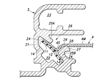
次に、図2を参照して、シェードシート4のガイド構造について説明する。図2は図1中のII-IIに沿って示す左のガイドレール3の横断面図である。左右のガイドレール3におけるシェードシート4のガイド構造は、左右対称である点を除いて同一である。以下、左のガイドレール3の右方を内方と称し、左方を外方と称する。
Next, referring to FIG. 2, the guide structure of the
シェードシート4の側縁には、側縁に沿って長手方向に延びる案内帯11が設けられている。案内帯11は、可撓性を有し、シェードシート4よりも大きな曲げ剛性を有する材料からなり、外力が加わっていない時に矩形の断面形状を有する平板状をしている。案内帯11は、ガイドレール3に対する摩擦係数が低い材料からなっていればよく、樹脂製や金属製であってよい。本実施形態の案内帯11はフッ素樹脂製とされている。
A side edge of the
案内帯11は、幅方向の略中央に設けられた止着部12を介してシェードシート4に結合されている。ここで、止着部12とはシェードシート4を止着する点であり、シェードシート4は止着部12から可撓性をもって延出する。本実施形態では、シェードシート4が側縁の近傍にて案内帯11の幅方向の略中央に糸13(図3参照)で縫合されることによって案内帯11に結合されている。案内帯11の外側の側面14はシェードシート4の側縁に整合しており、案内帯11の外側の半分はシェードシート4の下面に当接している。
The
図2に示される展開状態では、案内帯11はシェードシート4の側部4Sに対して略直交する角度に保持される。巻取軸5に巻き取られた巻取状態では、案内帯11はシェードシート4の下方にてシェードシート4と平行になり、シェードシート4と共に巻き取られる。ガイドレール3の近位端と巻き取られたシェードシート4と間の離間部分(図1参照)は案内帯11の角度変更区間であり、この部分では案内帯11は長手方向にねじれている。
In the unfolded state shown in FIG. 2, the
シェードシート4の縫合位置(止着部12)から側縁に至る部分は縫合による結合力を維持する部分であり、シェードシート4の実質的な端縁は止着部12に止着された部分である。シェードシート4の止着部12に止着された部分から側縁に至る部分は、案内帯11に接着されていてもよく、接着されていなくてもよい。他の実施形態では、当該部分が接着剤によって案内帯11に接着されることで案内帯11がシェードシート4に結合されてもよい。所定の結合力が得られれば、シェードシート4の側縁が案内帯11の止着部12に止着されてもよい。
A portion from the sewing position (fastening portion 12) of the
ガイドレール3は、上下に2段の構造とされたレール基部21を備えており、下段に案内帯11を受容する帯ガイド溝22を、上段にプッシュプルケーブルを受容するケーブルガイド溝23を有している。ケーブルガイド溝23は内方に開放されており、プッシュプルケーブルに結合される図示しないスライダは、ケーブルガイド溝23の開放部から内方へ延出し、クロスバー8に連結される。
The
レール基部21の下段部には、上方に向けて外方へ傾斜し、案内帯11を係止する係止面24を有し、案内帯11を係止するガイド壁25(25A、25B)が一体形成されている。帯ガイド溝22は、ガイド壁25の幅方向の中間部に開放部を有している。シェードシート4はこの帯ガイド溝22の開放部を通ってガイドレール3の内方へ延出する。すなわち、ガイド壁25に形成されたこの開放部はシェードシート4を通過させるスロット26である。
At the lower part of the
ガイド壁25はスロット26によって、外側に位置する上ガイド壁25Aと内側に位置する下ガイド壁25Bとに分断されている。ガイド壁25は、スロット26が形成された部分では案内帯11を係止できない。そのため、スロット26の幅はシェードシート4の厚みよりも大きい範囲で可及的に小さいほうが好ましい。スロット26の幅は、ガイドレール3の製造に用いる金型の形状によって定まり、本実施形態ではシェードシート4の厚みの数倍程度、且つ案内帯11の幅W11(図3参照)の3分の1程度とされている。
The guide wall 25 is divided by a
下ガイド壁25Bの上端には、止着部12からスロット26を通過して内方へ延出するシェードシート4をガイドするガイド部27が一体形成されている。ガイド部27は、下ガイド壁25Bの上端から上内方へ延出しており、シェードシート4の下面に当接する当接面28を有している。当接面28は、シェードシート4のスロット26を通過する側部4Sと左右のガイド部27間に張設される主部4Mとに接する円弧をなし、直線状の延長部29を介してスロット26を画定する下ガイド壁25Bの端面に連続している。
A
シェードシート4には、左右のガイドレール3から案内帯11を介して左右方向の張力が付与される。したがって、案内帯11の止着部12にはシェードシート4から引張力(図3に示す矢印参照)が作用する。シェードシート4はガイド部27があることによって止着部12から案内帯11に対して略直角に延出している。
A lateral tension is applied to the
上ガイド壁25Aの係止面24はシェードシート4を介して案内帯11を係止する。上記のように案内帯11の左側部分にはシェードシート4がなくてもよく、この場合には係止面24は案内帯11の表面に当接して案内帯11を直接係止する。下ガイド壁25Bの係止面24は案内帯11の止着部12側の表面に当接して案内帯11を直接係止する。
The engaging
ガイド壁25は案内帯11の幅W11よりも大きな内空を有する帯ガイド溝22を画定しており、ガイド壁25の係止面24は案内帯11の幅W11よりも大きな幅W24(図3参照)を有している。そして係止面24は、シェードシート4の延出方向(内方)に向けて凸に湾曲しており、案内帯11の両側縁から更に延出している。したがって、案内帯11の両側方には空間が形成され、案内帯11の両側面14はガイドレール3に当接していない。
The guide wall 25 defines a
案内帯11の止着部12にシェードシート4からの引張力が作用することから、案内帯11は撓み、ガイド壁25の係止面24に沿って湾曲している。具体的には、案内帯11は、図2の横断面において止着部12が内上方へ凸になる向きに湾曲し、スロット26に対応する部分以外の面の全体で係止面24に当接している。ガイド壁25の係止面24の曲率は、張力によって撓む案内帯11の形状に合わせて当接部の面圧が均等になるように設定されている。
Since the tensile force from the
図3はこのように構成されたシェードガイド構造を模式的に示す図2に対応する断面図である。以下、図2及び図3を参照して、実施形態に係るシェードガイド構造の作用効果を説明する。 FIG. 3 is a cross-sectional view corresponding to FIG. 2 schematically showing the shade guide structure thus constructed. Hereinafter, the effects of the shade guide structure according to the embodiment will be described with reference to FIGS. 2 and 3. FIG.
ガイド壁25は、横断面においてシェードシート4に対して傾斜し、案内帯11を係止する係止面24を有しており、これにより、案内帯11がガイド壁25の係止面24によって傾斜した姿勢に保持される。そのため、案内帯11がシェードシート4に対して垂直に保持される場合に比べ、案内帯11のガイドレール3の形状に対する追従性がよい。したがって、上下方向に湾曲したルーフ等の用途へのシェードガイド構造の適用が可能になる。
The guide wall 25 is inclined with respect to the
ガイド壁25にはシェードシート4が通過するスロット26形成され、ガイド部27がシェードシート4に当接することにより、シェードシート4が止着部12から案内帯11に対して略直角に延出している。これにより、案内帯11は止着部12においてシェードシート4から垂直に引張力を受けて止着部12側の表面をガイド壁25の係止面24に当接させるため、当接部の面圧が低い。したがって、シェードシート4の巻き取り及び引き出し時における摺動抵抗が小さく、摺動部の磨耗が抑制される。
A
なお、ガイド部27は断面においてシェードシート4の延在方向を変更させる機能を果たし、シェードシート4の側部4Sは主部4Mに対して傾斜する。しかしながら、案内帯11がシェードシート4の主部4Mに対して傾斜しているため、シェードシート4の延在方向の変更角度は小さく、ガイド部27がシェードシート4に加える押圧力は小さい。したがって、シェードシート4とガイド部27との摺動抵抗は小さく、シェードシート4の磨耗の虞は低い。
The
ガイド壁25の係止面24は横断面において案内帯11の幅W11よりも大きな幅W24を有し、案内帯11の両側面14がガイドレール3に当接していない。そのため、案内帯11がスロット26に対向する部分以外の面の全体で係止面24に当接する。すなわち、図4に示すように、案内帯11の側面14がガイドレール3に当接すると、案内帯11が係止面24に面接触しなくなる。また当接部の圧力が高くなって摺動抵抗が増大する。これに対し本実施形態では、案内帯11がスロット26に対向する部分以外の面の全体で係止面24に当接することにより、当接部の面圧が低くなり、摺動部の磨耗が抑制される。また、案内帯11の両側面14がガイドレール3に当接しないため、案内帯11とガイドレール3との摺動摩擦の増大が防止される。
The locking
図1及び図2に示すように、左右のガイドレール3は案内帯11を介してシェードシート4に左右方向の張力を付与する間隔をもって配置されており、これによりシェードシート4が左右方向に弛みにくい。また、ガイド壁25の係止面24は張力によって撓む案内帯11の形状に合わせて湾曲している。これにより、案内帯11と係止面24との当接部における面圧分布が均一化される。したがって、案内帯11及びガイド壁25の偏磨耗が抑制される。
As shown in FIGS. 1 and 2, the left and
図2及び図3に示すように、ガイド部27は、横断面においてシェードシート4のスロット26を通過する側部4Sと左右のガイド部27間に張設される主部4Mとに接する円弧をなす当接面28を有している。そのため、シェードシート4がガイド部27との摺動によって擦れることが抑制される。
As shown in FIGS. 2 and 3, the
図2に示すように、ガイド部27はガイド壁25に一体に形成され、当接面28はスロット26を画定するガイド壁25の端面に延長部29を介して連続している。そのため、ガイドレール3が1部材で済み、シェードガイド構造の製造及び組立が容易である。なお、延長部29は、本実施形態ではシェードシート4の側部4Sに当接するが、図3に示すような他の実施形態ではシェードシート4に当接しなくてもよい。
As shown in FIG. 2, the
以上で具体的実施形態の説明を終えるが、本発明は上記実施形態に限定されることなく幅広く変形実施することができる。例えば、上記実施形態で説明した各部材や部位の具体的構成や配置、数量、素材、手順などは、本発明の趣旨を逸脱しない範囲であれば適宜変更可能である。一方、上記実施形態に示した各構成要素は必ずしも全てが必須ではなく、適宜選択することができる。 Although the specific embodiments have been described above, the present invention is not limited to the above embodiments and can be widely modified. For example, the specific configuration, arrangement, quantity, material, procedure, etc. of each member and part described in the above embodiment can be changed as appropriate without departing from the gist of the present invention. On the other hand, not all of the components shown in the above embodiments are essential, and can be selected as appropriate.
1 シェード装置
2 ロールシェード
3 ガイドレール
4 シェードシート
4M 主部
4S 側部
5 巻取軸
11 案内帯
12 止着部
14 側面
22 帯ガイド溝
24 係止面
25 ガイド壁
25A 上ガイド壁
25B 下ガイド壁
26 スロット
27 ガイド部
28 当接面
29 延長部
W11 案内帯11の幅
W24 係止面の幅REFERENCE SIGNS
Claims (5)
巻取軸に巻き取り及び引き出し可能に巻かれたシェードシートと、
前記シェードシートの両側縁に沿って設けられ、幅方向の略中央に設けられた止着部を介して前記シェードシートに結合され、外力が加わっていない状態で矩形の断面形状を有する案内帯と、
前記シェードシートの前記巻き取り及び前記引き出し時に前記案内帯を長手方向にガイドする左右のガイドレールとを有し、
左右の前記ガイドレールが、前記案内帯を介して前記シェードシートに左右方向の張力を付与する間隔をもって配置され、
前記ガイドレールが、
横断面において前記シェードシートに対して傾斜し、前記案内帯を係止する係止面を有するガイド壁と、
前記ガイド壁に形成され、前記シェードシートが通過するスロットと、
前記シェードシートが前記止着部から前記案内帯に対して略直角に延出するように前記シェードシートに当接するガイド部とを有し、
前記シェードシートが、左右の前記ガイド部間に張設される主部と、前記主部に対して傾斜し、前記止着部から前記案内帯に対して略直角に延出して前記スロットを通過する左右の側部とを有し、
前記ガイド壁の前記係止面が、前記張力によって撓む前記案内帯の形状に合わせて前記シェードシートの延出方向に向けて凸に湾曲していることを特徴とするシェードガイド構造。A shade guide structure,
a shade sheet wound around a winding shaft so as to be wound up and pulled out;
a guide band provided along both side edges of the shade sheet, coupled to the shade sheet via fastening portions provided substantially in the center in the width direction, and having a rectangular cross-sectional shape in a state where no external force is applied; ,
left and right guide rails for guiding the guide band in the longitudinal direction when the shade sheet is wound and pulled out;
The left and right guide rails are arranged with a spacing that imparts tension in the left-right direction to the shade sheet via the guide band,
The guide rail is
a guide wall inclined with respect to the shade sheet in cross section and having an engaging surface for engaging the guide band;
a slot formed in the guide wall through which the shade sheet passes;
a guide portion that abuts on the shade sheet so that the shade sheet extends from the fastening portion at a substantially right angle to the guide band;
The shade sheet has a main portion stretched between the left and right guide portions, is inclined with respect to the main portion, extends from the fastening portion at a substantially right angle to the guide band, and passes through the slot. and left and right sides for
A shade guide structure, wherein the locking surface of the guide wall is convexly curved in the extending direction of the shade sheet in conformity with the shape of the guide band that is bent by the tension.
Applications Claiming Priority (3)
| Application Number | Priority Date | Filing Date | Title |
|---|---|---|---|
| JP2020066691 | 2020-04-02 | ||
| JP2020066691 | 2020-04-02 | ||
| PCT/JP2021/008080 WO2021199862A1 (en) | 2020-04-02 | 2021-03-03 | Shade guide structure |
Publications (3)
| Publication Number | Publication Date |
|---|---|
| JPWO2021199862A1 JPWO2021199862A1 (en) | 2021-10-07 |
| JPWO2021199862A5 JPWO2021199862A5 (en) | 2022-10-12 |
| JP7153165B2 true JP7153165B2 (en) | 2022-10-13 |
Family
ID=77930323
Family Applications (1)
| Application Number | Title | Priority Date | Filing Date |
|---|---|---|---|
| JP2022511685A Active JP7153165B2 (en) | 2020-04-02 | 2021-03-03 | Shade guide structure |
Country Status (4)
| Country | Link |
|---|---|
| US (1) | US20230113002A1 (en) |
| JP (1) | JP7153165B2 (en) |
| CN (1) | CN115398075A (en) |
| WO (1) | WO2021199862A1 (en) |
Cited By (1)
| Publication number | Priority date | Publication date | Assignee | Title |
|---|---|---|---|---|
| JP7450199B1 (en) | 2022-12-07 | 2024-03-15 | 寧波森瑞機電技術有限公司 | Electric awning curtains that are easy and quick to assemble |
Citations (2)
| Publication number | Priority date | Publication date | Assignee | Title |
|---|---|---|---|---|
| JP4936139B2 (en) | 2004-11-19 | 2012-05-23 | ベバスト・アクチィエンゲゼルシャフト | Rolling blind device for vehicle |
| JP2013506592A (en) | 2010-04-26 | 2013-02-28 | ベバスト・アクチィエンゲゼルシャフト | Roller blind device for vehicle, subassembly including roller blind device for vehicle, and roof device |
Family Cites Families (11)
| Publication number | Priority date | Publication date | Assignee | Title |
|---|---|---|---|---|
| DE19941984C1 (en) * | 1999-09-03 | 2000-10-19 | Porsche Ag | Multi-part sliding roof for a cross country vehicle sunroof has sections with independent movements to be set in a variety of configurations and is flush with the roof when closed without projecting guides |
| DE102004017459A1 (en) * | 2004-04-08 | 2005-10-27 | Arvinmeritor Gmbh | Roller blind for a sunroof system |
| DE502007003134D1 (en) * | 2007-01-31 | 2010-04-29 | Arvinmeritor Gmbh | Guiding system for a roller blind of a sunroof system |
| US20090178771A1 (en) * | 2008-01-15 | 2009-07-16 | Macauto Industrial Co., Ltd. | Vehicle sunshade assembly |
| WO2010022769A1 (en) * | 2008-08-27 | 2010-03-04 | Inalfa Roof Systems Group B.V. | Sunshade assembly and open roof construction provided therewith |
| KR20110127130A (en) * | 2009-03-17 | 2011-11-24 | 다이쿄니시카와 가부시키가이샤 | Sunshade structure |
| JP5458695B2 (en) * | 2009-06-29 | 2014-04-02 | アイシン精機株式会社 | Roll shade device |
| CN204037295U (en) * | 2014-07-09 | 2014-12-24 | 韦巴斯托股份公司 | For the roller blind device of self-propelled vehicle |
| CN204161047U (en) * | 2014-07-09 | 2015-02-18 | 韦巴斯托股份公司 | For the roller blind device of self-propelled vehicle |
| JP2016022817A (en) * | 2014-07-18 | 2016-02-08 | アイシン精機株式会社 | Roll shade device |
| DE102016122700A1 (en) * | 2016-11-24 | 2018-05-24 | Roof Systems Germany Gmbh | Sun blind, sunroof system with such a sun blind and method for producing a sun blinds |
-
2021
- 2021-03-03 JP JP2022511685A patent/JP7153165B2/en active Active
- 2021-03-03 CN CN202180026159.9A patent/CN115398075A/en active Pending
- 2021-03-03 WO PCT/JP2021/008080 patent/WO2021199862A1/en active Application Filing
- 2021-03-03 US US17/915,655 patent/US20230113002A1/en active Pending
Patent Citations (2)
| Publication number | Priority date | Publication date | Assignee | Title |
|---|---|---|---|---|
| JP4936139B2 (en) | 2004-11-19 | 2012-05-23 | ベバスト・アクチィエンゲゼルシャフト | Rolling blind device for vehicle |
| JP2013506592A (en) | 2010-04-26 | 2013-02-28 | ベバスト・アクチィエンゲゼルシャフト | Roller blind device for vehicle, subassembly including roller blind device for vehicle, and roof device |
Cited By (1)
| Publication number | Priority date | Publication date | Assignee | Title |
|---|---|---|---|---|
| JP7450199B1 (en) | 2022-12-07 | 2024-03-15 | 寧波森瑞機電技術有限公司 | Electric awning curtains that are easy and quick to assemble |
Also Published As
| Publication number | Publication date |
|---|---|
| CN115398075A (en) | 2022-11-25 |
| WO2021199862A1 (en) | 2021-10-07 |
| JPWO2021199862A1 (en) | 2021-10-07 |
| US20230113002A1 (en) | 2023-04-13 |
Similar Documents
| Publication | Publication Date | Title |
|---|---|---|
| US8955575B2 (en) | Roller blind system for a motor vehicle | |
| US7220129B1 (en) | Electric supply device for slide structure | |
| CN102470736B (en) | Vehicle roller blind arrangement, assembly having a vehicle roller blind arrangement, and roof arrangement | |
| JP2726780B2 (en) | Wire guide device | |
| JP7153165B2 (en) | Shade guide structure | |
| US20110227371A1 (en) | Sunshade assembly and open roof construction provided therewith | |
| JP2006074980A (en) | Electric power supply device for slide structure | |
| SK280957B6 (en) | Roller blind, particularly for use as blackout shade | |
| KR20090033415A (en) | Closure device with a curtain having flexible lateral edges | |
| CN109153365A (en) | Belt deflector device | |
| US7534959B2 (en) | Power supply device | |
| US20080272612A1 (en) | Covering Device for Glazing in a Vehicle | |
| CN111065782A (en) | Profiled beam element comprising a deformable area for absorbing deformation of said profiled beam element during fixation thereof | |
| CN102806829A (en) | Sunshade assembly and open roof construction provided therewith | |
| DE59206167D1 (en) | Curtain for a non-rectangular (glass) surface | |
| JP2012516799A (en) | Sunshade assembly | |
| JP6820004B2 (en) | Roll screen device | |
| US577244A (en) | Shade-holding mechanism | |
| JP2527330Y2 (en) | Winding screen device | |
| JPWO2021199862A5 (en) | ||
| US7081588B2 (en) | Electric power supplying device | |
| JP2022049360A (en) | Roll screen device | |
| US10544855B2 (en) | Chain guide | |
| JP4883713B2 (en) | Sheet fixing device | |
| JP2022138003A (en) | screen device |
Legal Events
| Date | Code | Title | Description |
|---|---|---|---|
| A529 | Written submission of copy of amendment under article 34 pct |
Free format text: JAPANESE INTERMEDIATE CODE: A5211 Effective date: 20220713 |
|
| A621 | Written request for application examination |
Free format text: JAPANESE INTERMEDIATE CODE: A621 Effective date: 20220713 |
|
| A871 | Explanation of circumstances concerning accelerated examination |
Free format text: JAPANESE INTERMEDIATE CODE: A871 Effective date: 20220713 |
|
| TRDD | Decision of grant or rejection written | ||
| A01 | Written decision to grant a patent or to grant a registration (utility model) |
Free format text: JAPANESE INTERMEDIATE CODE: A01 Effective date: 20220920 |
|
| A61 | First payment of annual fees (during grant procedure) |
Free format text: JAPANESE INTERMEDIATE CODE: A61 Effective date: 20220930 |
|
| R150 | Certificate of patent or registration of utility model |
Ref document number: 7153165 Country of ref document: JP Free format text: JAPANESE INTERMEDIATE CODE: R150 |