EP1584422A1 - Verfahren und Einrichtung zur Reduktion von Druckspitzen in einer Handwerkzeugmaschine mit elektropneumatischem Schlagwerk - Google Patents
Verfahren und Einrichtung zur Reduktion von Druckspitzen in einer Handwerkzeugmaschine mit elektropneumatischem Schlagwerk Download PDFInfo
- Publication number
- EP1584422A1 EP1584422A1 EP04101433A EP04101433A EP1584422A1 EP 1584422 A1 EP1584422 A1 EP 1584422A1 EP 04101433 A EP04101433 A EP 04101433A EP 04101433 A EP04101433 A EP 04101433A EP 1584422 A1 EP1584422 A1 EP 1584422A1
- Authority
- EP
- European Patent Office
- Prior art keywords
- piston
- spring
- electropneumatic
- exciter
- compression spring
- Prior art date
- Legal status (The legal status is an assumption and is not a legal conclusion. Google has not performed a legal analysis and makes no representation as to the accuracy of the status listed.)
- Granted
Links
- 238000009527 percussion Methods 0.000 title claims description 9
- 238000000034 method Methods 0.000 title claims description 4
- 230000006835 compression Effects 0.000 claims abstract description 37
- 238000007906 compression Methods 0.000 claims abstract description 37
- 230000005284 excitation Effects 0.000 claims abstract description 33
- 230000007246 mechanism Effects 0.000 claims description 19
- 238000005553 drilling Methods 0.000 claims description 3
- 230000009471 action Effects 0.000 claims description 2
- 230000009467 reduction Effects 0.000 abstract description 3
- 230000001133 acceleration Effects 0.000 description 11
- 230000035939 shock Effects 0.000 description 7
- 230000033001 locomotion Effects 0.000 description 6
- 239000002655 kraft paper Substances 0.000 description 3
- 238000005457 optimization Methods 0.000 description 3
- 238000007789 sealing Methods 0.000 description 3
- 230000005540 biological transmission Effects 0.000 description 2
- 230000001186 cumulative effect Effects 0.000 description 2
- 238000010586 diagram Methods 0.000 description 2
- 238000006073 displacement reaction Methods 0.000 description 2
- 238000005065 mining Methods 0.000 description 2
- 230000000737 periodic effect Effects 0.000 description 2
- 230000036316 preload Effects 0.000 description 2
- 238000000418 atomic force spectrum Methods 0.000 description 1
- 230000035559 beat frequency Effects 0.000 description 1
- 230000008901 benefit Effects 0.000 description 1
- 230000008859 change Effects 0.000 description 1
- 238000012885 constant function Methods 0.000 description 1
- 230000007423 decrease Effects 0.000 description 1
- 230000001419 dependent effect Effects 0.000 description 1
- 230000006872 improvement Effects 0.000 description 1
- 230000010354 integration Effects 0.000 description 1
- 230000003993 interaction Effects 0.000 description 1
- 238000013178 mathematical model Methods 0.000 description 1
- 230000007935 neutral effect Effects 0.000 description 1
Images


Classifications
-
- B—PERFORMING OPERATIONS; TRANSPORTING
- B25—HAND TOOLS; PORTABLE POWER-DRIVEN TOOLS; MANIPULATORS
- B25D—PERCUSSIVE TOOLS
- B25D11/00—Portable percussive tools with electromotor or other motor drive
- B25D11/06—Means for driving the impulse member
- B25D11/12—Means for driving the impulse member comprising a crank mechanism
- B25D11/125—Means for driving the impulse member comprising a crank mechanism with a fluid cushion between the crank drive and the striking body
-
- B—PERFORMING OPERATIONS; TRANSPORTING
- B25—HAND TOOLS; PORTABLE POWER-DRIVEN TOOLS; MANIPULATORS
- B25D—PERCUSSIVE TOOLS
- B25D17/00—Details of, or accessories for, portable power-driven percussive tools
- B25D17/06—Hammer pistons; Anvils ; Guide-sleeves for pistons
-
- B—PERFORMING OPERATIONS; TRANSPORTING
- B25—HAND TOOLS; PORTABLE POWER-DRIVEN TOOLS; MANIPULATORS
- B25D—PERCUSSIVE TOOLS
- B25D17/00—Details of, or accessories for, portable power-driven percussive tools
- B25D17/24—Damping the reaction force
-
- B—PERFORMING OPERATIONS; TRANSPORTING
- B25—HAND TOOLS; PORTABLE POWER-DRIVEN TOOLS; MANIPULATORS
- B25D—PERCUSSIVE TOOLS
- B25D2217/00—Details of, or accessories for, portable power-driven percussive tools
- B25D2217/0011—Details of anvils, guide-sleeves or pistons
- B25D2217/0023—Pistons
-
- B—PERFORMING OPERATIONS; TRANSPORTING
- B25—HAND TOOLS; PORTABLE POWER-DRIVEN TOOLS; MANIPULATORS
- B25D—PERCUSSIVE TOOLS
- B25D2250/00—General details of portable percussive tools; Components used in portable percussive tools
- B25D2250/371—Use of springs
Definitions
- the invention relates to a method for reducing pressure peaks in an electropneumatic percussion of a hand tool, at the an electric motor driven excitation piston via one of this compressed gas spring acts on an intermediate piston, in turn driving a tool hitting.
- the invention also relates to an electropneumatic striking mechanism a hand tool with an electric motor driven Exciter piston that compressed over one of this during a working stroke Gas spring on an intermediate piston driving a tool acts.
- an electric motor is an excitation piston cyclically via an eccentric shaft (connecting rod drive) or a swashplate driven back and forth.
- the exciter piston acts via a from this compressed gas-in particular air spring on a flying piston, either directly on a tool holder and thus on a tool bounces, possibly via an interposed further air shock pad or over an anvil, which then in turn a shock wave to the tool with which the mining of a subsoil takes place.
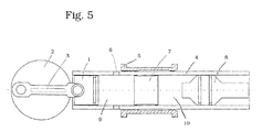
- FIG. 5 of the accompanying drawings illustrates the basic Principle of a conventional electro-pneumatic impact mechanism, as it used for example in drilling and / or chipping hammers.
- a Excitation piston 1 In the region of a drive-side end of a guide tube 4 is a Excitation piston 1 through a through an eccentric disc or shaft 2 by a connecting rod 3 cyclically, d. H. reciprocating, powered.
- FIG. 5 illustrates the rear or top dead center of the exciter piston 1.
- the excitation piston begins 1 its working stroke while compressing an air cushion or shock pad, hereinafter referred to as air spring 9, if previously Schnaufö Stamm 6, which are used in particular for idle shutdown of the striking mechanism, closed by an axially displaceable slide or valve sleeve 5 are.
- air spring 9 of the excitation piston 1 acts on a flying piston 7, which is greatly accelerated and its kinetic energy either via a shock pad 10 or optionally directly on an anvil 8 acts, the thereby generated shock wave on a (not shown) tool holder or so on a tool, in particular a chisel transfers.
- the flying piston 7 in a working stroke of the excitation piston 1 via the air spring 9 forward, ie accelerated in the direction of striker 8, so he meets with a terminal velocity v before on the striker 8 and is reflected at this.
- the shock generates a shock wave that propagates through the striker 8 to the tool tip and there performs the actual mining work.
- the flying mass 7 flies back at a reduced speed.
- a special problem is also caused by the high pressure peaks Vibrations, especially the hand-arm system of a device user strain.
- the invention is based on the object Pressure peaks in the electro-pneumatic impact mechanism of a hand-held power tool to reduce.
- a solution to this problem would not only be a reduction in vibration levels on the hand-arm system, but at the same time or higher impact performance open up the opportunity, the transmission elements Slimmer and thus make the device easier to build to be able to.
- This object is achieved procedurally according to the invention, that the characteristic of the force of the air spring during rebound of the intermediate piston, So of the flying piston or, if this is not present, then as an intermediate piston acting Döppers, by the action of a mechanical Compression spring is linearized.
- This method is particularly suitable for use with electropneumatic impactors in drilling and / or Chisel hammers.
- An electropneumatic percussion of a hand tool with an electric motor driven excitation piston the one in this during a working stroke compressed gas, in particular air spring on a hammer acting on the tool driving intermediate piston acts according to the invention characterized by a between the exciter piston and the intermediate piston acting additional mechanical elastic spring.
- This additional elastic compression spring can be on the excitation piston or be attached to the intermediate piston, in particular on the flying piston.
- FIG. 1 shows that shown in FIG. 5 corresponding neutral position; the excitation piston 1 is in the upper or rear dead center; the Schnaufö réelleen 6 are at forward or down shifted control sleeve 5 released.
- Fig. 2 illustrates an intermediate position of the excitation piston 1 at its backward stroke, at the time to which the subsequent Aero-piston 7 the protruding with relieved pressure spring 12 bounce sleeve 11 reaches, ie the time at which the elastic compression spring 12 to starts acting.
- the air spring 9 is now in the space within the above Prellhülse 11 caught.
- integrated elastic compression spring 12 is now parallel to Air spring 9 connected and is compressed. This will change the characteristic the air spring 9 linearized, which causes the pressure or force peaks smoothed and reduced.
- the acceleration phase on the backward stroke the exciter piston 1 is extended and more uniform and can be relatively close to the optimum of a constant acceleration phase come so that opposite to the spike-like accelerations through the compression of the air spring 9 alone achieved a significant improvement becomes.
- the air spring 9 is strongly compressed. simultaneously but is also due to the displacement of the baffle sleeve 11 to the rear elastic compression spring 12 compressed. Even before the compression spring 12th is completely compressed, the characteristic of the air spring 9 increases so much that the latter dominates the characteristic of the two parallel-acting springs.
- x 0 basically designates the position at which the pressure p 0 is measured. If the external pressure is applied for p 0 (1 bar), then x 0 denotes the mean percussion length, since a negative pressure is generated in the operating state at the maximum distance between excitation piston 1 and flying piston 7.
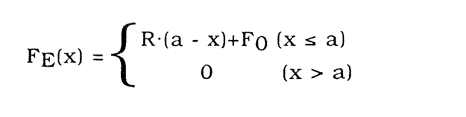
- the elastic compression spring 12 on the other hand has a more or less linear spring characteristic F E (x). From a certain distance a from the front surface 18 of the exciter piston 1 (see Fig. 2), it is used:
- the graph of Fig. 4 shows the force curve (top) of the combination of the air spring 9 and an elastic compression spring 12, designed for a pneumatic percussion of a drill and / or chisel hammer.
- the air spring 9 developed only at very small distances between flight and Exciter pistons of less than, for example, 7 mm relevant forces. This can be seen well from the characteristic of the percentage increase in strength as Function of the distance x between flying and exciter pistons.
- the curve c the cumulative curve from a and b leaves the function of the additional elastic Compression spring 12, namely the long range of the interaction force Detect between excitation piston 1 and flying piston 7. From one certain distance between exciter and flying piston dominates the elastic Compression spring 12 via the air spring 9. In this area, the behavior mainly determined by the elastic compression spring, d. h., the Force-displacement curve is linear to a good approximation, resulting from the cumulative curve c is clearly visible.
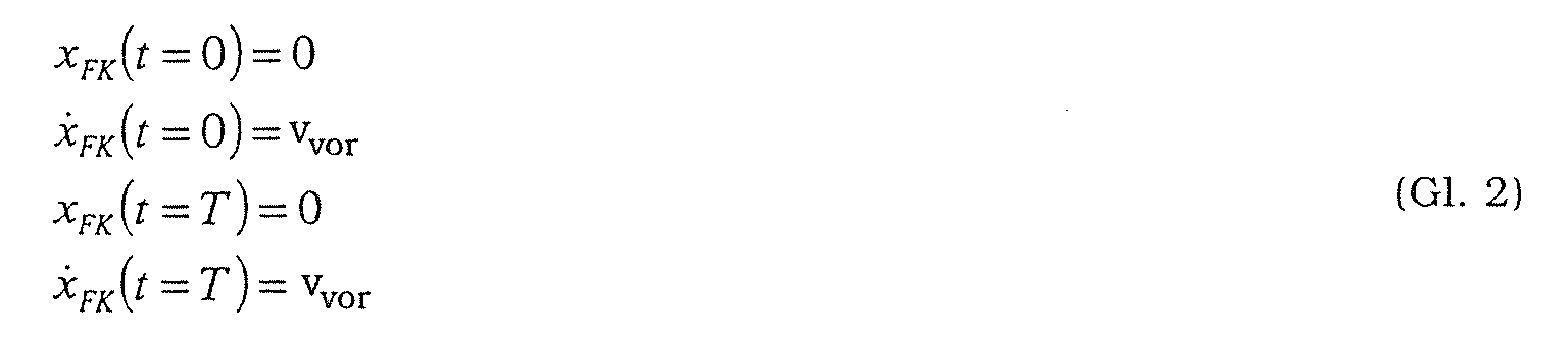
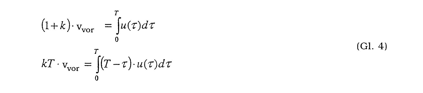
- x FK denotes the position of the flying mass 7, measured from the position of the impact in the direction of the striker 8, ie x FK is negative, when a movement towards the exciter piston 1 is assumed to be a positive speed.
- u (t) denotes the acceleration of the flying mass in [m / s 2 ] and m FK the mass of the flying mass in [kg].
- An advantageous result of the invention thus results in an optimization the aircraft piston acceleration also an optimization, so one Minimization of hand-arm vibration.
Landscapes
- Engineering & Computer Science (AREA)
- Mechanical Engineering (AREA)
- Percussive Tools And Related Accessories (AREA)
Abstract
Description
- Fig. 1
- in einer Schnittdarstellung den prinzipiellen Aufbau eines elektropneumatischen Schlagwerks mit parallel geschalteter, elastischer, mechanischer Druckfeder in hinterer Totpunktposition des Erregerkolbens;
- Fig. 2
- eine Zwischenposition im Arbeitshub des Erregerkolbens, bei der die elastische Druckfeder zu wirken beginnt, wenn der Flugkolben und eine Prellhülse am Erregerkolben aufeinander treffen;
- Fig. 3
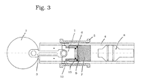
- eine Hubposition des Erregerkolbens, insbesondere den unteren oder vorderen Totpunkt, bei der die erfindungsgemäße elastische Druckfeder vollständig oder weitgehend vollständig komprimiert ist;
- Fig. 4
- die Zunahme der Kraft zwischen Flug- und Erregerkolben, d. h. die durch die Druckkraft der Luftfeder aufgebaute Kraft (oben) bzw. die Zunahme der Kraft (unten), beides aufgetragen über dem Abstand zwischen Flugkolben und Erregerkolben bei zurückfahrendem Erregerkolben und nachfolgendem Flugkolben.
- x:
- der variable Kompressionweg der Luftfeder oder der Abstand zwischen der Vorderfläche 18 des Erregerkolbens 1 und der Hinterfläche 17 des Flugkolbens 7;
- A:
- die Querschnittsfläche des Flugkolbens (bzw. Erregerkolbens);
- d:
- der Durchmesser des Flugkolbens (bzw. Erregerkolbens).

| Führungsrohrdurchmesser: | d = 30 mm |
| Maximaler Kompressionsweg der Luftfeder: | x0 = 35 mm |
| Außendruck: | p0 = 1 bar |
| Isotropenkoeffizient für Luft: | κ = 1.4 |
| Federkonstante der zusätzlichen Druckfeder: | R = 30 N/mm |
| Wirkabstand der zusätzlichen Druckfeder: | a = 25 mm |
| Vorspannung der zusätzlichen Druckfeder: | F0 = 10N. |






- Lit. [1]:
- Babitsky, V. I.: Theory of Vibro Impact Systems and Applications. Springer Verlag, Berlin 1998.
- Lit. [2]:
- Babitsky, V. I.: Handheld Percussion Machine as a discrete nonlinear converter. Journal of Sound and Vibration, 214(1): 165-182, 1998.
Claims (9)
- Verfahren zur Reduktion von Druckspitzen in einem elektropneumatischen Schlagwerk einer Handwerkzeugmaschine, bei dem ein elektromotorisch angetriebener Erregerkolben über eine von diesem komprimierte Gasfeder auf einen Zwischenkolben wirkt, der seinerseits ein Werkzeug schlagend antreibt, dadurch gekennzeichnet, dass die Kennlinie der Kraft der Luftfeder beim Rückprall des Zwischenkolbens durch die Wirkung einer mechanischen Druckfeder linearisiert wird.
- Elektropneumatisches Schlagwerk einer Handwerkzeugmaschine mit einem elektromotorisch angetriebenen Erregerkolben, der über eine von diesem bei einem Arbeitshub komprimierte Gasfeder auf einen ein Werkzeug schlagend antreibenden Zwischenkolben wirkt, gekennzeichnet durch eine zwischen dem Erregerkolben (1) und dem Zwischenkolben (7) wirkende zusätzliche, elastische, mechanische Druckfeder (12).
- Elektropneumatisches Schlagwerk nach Anspruch 2, dadurch gekennzeichnet, dass die elastische Druckfeder am Erregerkolben angebracht ist.
- Elektropneumatisches Schlagwerk nach Anspruch 2, dadurch gekennzeichnet, dass die elastische Druckfeder am Zwischenkolben angebracht ist.
- Elektropneumatisches Schlagwerk nach Anspruch 3 oder 4, dadurch gekennzeichnet, dass die am Erregerkolben oder am Zwischenkolben angebrachte Druckfeder über eine den Kolbenmantel umgebende, relativ zum Kolben (1 oder 7) axial verschiebliche Prellhülse (11) auf den Zwischenkolben (7) einerseits bzw. den Erregerkolben (1) andererseits wirkt.
- Elektropneumatisches Schlagwerk nach Anspruch 5, dadurch gekennzeichnet, dass die Federhärten bzw. Federkennlinien der Luftfeder (9) einerseits und der elastischen Druckfeder (12) andererseits so aufeinander abgestimmt sind, dass Druckspitzen auf den Antrieb des Erregerkolbens gegenüber einem druckfederlosen Schlagwerk deutlich reduziert sind.
- Elektropneumatisches Schlagwerk nach Anspruch 6, dadurch gekennzeichnet, dass die elastische Druckfeder so ausgelegt ist, dass sie bei maximaler Einzelhubkompression der Luftfeder, d. h. bei geringstem Abstand zwischen Erreger- und Zwischenkolben, weitgehend vollständig komprimiert ist.
- Elektropneumatisches Schlagwerk nach Anspruch 5, gekennzeichnet durch eine Umlaufdichtung (12, 13) zwischen der freien Umrandungsstirnfläche der Prellhülse (11) und der gegenüberstehenden Stirnfläche des Zwischen- bzw. des Erregerkolbens.
- Bohr- und/oder Meisselhammer, ausgerüstet mit einem elektropneumatischen Schlagwerk nach einem der vorstehenden Ansprüche 2 bis 8.
Priority Applications (2)
| Application Number | Priority Date | Filing Date | Title |
|---|---|---|---|
| DE502004008342T DE502004008342D1 (de) | 2004-04-07 | 2004-04-07 | Verfahren und Einrichtung zur Reduktion von Druckspitzen in einer Handwerkzeugmaschine mit elektropneumatischem Schlagwerk |
| EP04101433A EP1584422B1 (de) | 2004-04-07 | 2004-04-07 | Verfahren und Einrichtung zur Reduktion von Druckspitzen in einer Handwerkzeugmaschine mit elektropneumatischem Schlagwerk |
Applications Claiming Priority (1)
| Application Number | Priority Date | Filing Date | Title |
|---|---|---|---|
| EP04101433A EP1584422B1 (de) | 2004-04-07 | 2004-04-07 | Verfahren und Einrichtung zur Reduktion von Druckspitzen in einer Handwerkzeugmaschine mit elektropneumatischem Schlagwerk |
Publications (2)
| Publication Number | Publication Date |
|---|---|
| EP1584422A1 true EP1584422A1 (de) | 2005-10-12 |
| EP1584422B1 EP1584422B1 (de) | 2008-10-29 |
Family
ID=34896124
Family Applications (1)
| Application Number | Title | Priority Date | Filing Date |
|---|---|---|---|
| EP04101433A Expired - Lifetime EP1584422B1 (de) | 2004-04-07 | 2004-04-07 | Verfahren und Einrichtung zur Reduktion von Druckspitzen in einer Handwerkzeugmaschine mit elektropneumatischem Schlagwerk |
Country Status (2)
| Country | Link |
|---|---|
| EP (1) | EP1584422B1 (de) |
| DE (1) | DE502004008342D1 (de) |
Cited By (5)
| Publication number | Priority date | Publication date | Assignee | Title |
|---|---|---|---|---|
| EP1652629A1 (de) * | 2004-10-26 | 2006-05-03 | Matsushita Electric Works, Ltd. | Schlagwerkzeug |
| EP2017038A1 (de) | 2007-07-19 | 2009-01-21 | HILTI Aktiengesellschaft | Handwerkzeugmaschine mit pneumatischem Schlagwerk |
| EP3260239A1 (de) * | 2016-06-24 | 2017-12-27 | HILTI Aktiengesellschaft | Handwerkzeugmaschine |
| WO2018228829A1 (de) * | 2017-06-12 | 2018-12-20 | Robert Bosch Gmbh | Handwerkzeugmaschine |
| US20230191576A1 (en) * | 2021-12-20 | 2023-06-22 | Nanjing Chervon Industry Co., Ltd. | Power tool and hammer drill |
Families Citing this family (3)
| Publication number | Priority date | Publication date | Assignee | Title |
|---|---|---|---|---|
| US10149711B2 (en) | 2012-03-30 | 2018-12-11 | Depuy Mitek, Llc | Surgical impact tool |
| US10814468B2 (en) | 2017-10-20 | 2020-10-27 | Milwaukee Electric Tool Corporation | Percussion tool |
| CN214723936U (zh) | 2018-01-26 | 2021-11-16 | 米沃奇电动工具公司 | 冲击工具 |
Citations (1)
| Publication number | Priority date | Publication date | Assignee | Title |
|---|---|---|---|---|
| DE2726214A1 (de) * | 1977-06-10 | 1978-12-21 | Hilti Ag | Bohrhammer mit pneumatisch angetriebenem schlagkolben |
Family Cites Families (8)
| Publication number | Priority date | Publication date | Assignee | Title |
|---|---|---|---|---|
| DE319367C (de) * | 1918-06-18 | 1920-03-04 | Automaten Handels Ges M B H De | Mechanisches Schlagwerkzeug mit freischwingendem Baer |
| US2067886A (en) * | 1935-09-13 | 1937-01-19 | Byford Electric Hammer Co Inc | Free piston power hammer |
| DE746442C (de) * | 1937-03-13 | 1944-08-10 | Siemens Ag | Federhammer |
| DE1206817B (de) * | 1959-04-04 | 1965-12-09 | Bosch Gmbh Robert | Motorisch angetriebener Hammer |
| DE3304916A1 (de) * | 1983-02-12 | 1984-08-16 | Robert Bosch Gmbh, 7000 Stuttgart | Bohrhammer |
| JPS6195807A (ja) * | 1984-10-12 | 1986-05-14 | Matsushita Electric Works Ltd | 衝撃電動工具 |
| DE3717694A1 (de) * | 1987-05-26 | 1988-12-08 | Bosch Gmbh Robert | Bohrhammer |
| US6958443B2 (en) * | 2003-05-19 | 2005-10-25 | Applied Digital Solutions | Low power thermoelectric generator |
-
2004
- 2004-04-07 DE DE502004008342T patent/DE502004008342D1/de not_active Expired - Lifetime
- 2004-04-07 EP EP04101433A patent/EP1584422B1/de not_active Expired - Lifetime
Patent Citations (1)
| Publication number | Priority date | Publication date | Assignee | Title |
|---|---|---|---|---|
| DE2726214A1 (de) * | 1977-06-10 | 1978-12-21 | Hilti Ag | Bohrhammer mit pneumatisch angetriebenem schlagkolben |
Cited By (15)
| Publication number | Priority date | Publication date | Assignee | Title |
|---|---|---|---|---|
| EP1652629A1 (de) * | 2004-10-26 | 2006-05-03 | Matsushita Electric Works, Ltd. | Schlagwerkzeug |
| US7828072B2 (en) | 2004-10-26 | 2010-11-09 | Panasonic Electric Works Co., Ltd. | Impact tool |
| EP2017038A1 (de) | 2007-07-19 | 2009-01-21 | HILTI Aktiengesellschaft | Handwerkzeugmaschine mit pneumatischem Schlagwerk |
| DE102007000393A1 (de) | 2007-07-19 | 2009-01-22 | Hilti Aktiengesellschaft | Handwerkzeugmaschine mit pneumatischem Schlagwerk |
| US8267189B2 (en) | 2007-07-19 | 2012-09-18 | Hilti Aktiengesellschaft | Hand-held power tool with a pneumatic percussion mechanism |
| WO2017220561A1 (de) * | 2016-06-24 | 2017-12-28 | Hilti Aktiengesellschaft | Handwerkzeugmaschine |
| EP3260239A1 (de) * | 2016-06-24 | 2017-12-27 | HILTI Aktiengesellschaft | Handwerkzeugmaschine |
| EP3722048A1 (de) * | 2016-06-24 | 2020-10-14 | Hilti Aktiengesellschaft | Handwerkzeugmaschine |
| US11117250B2 (en) | 2016-06-24 | 2021-09-14 | Hilti Aktiengesellschaft | Hand-held machine tool |
| WO2018228829A1 (de) * | 2017-06-12 | 2018-12-20 | Robert Bosch Gmbh | Handwerkzeugmaschine |
| CN110785264A (zh) * | 2017-06-12 | 2020-02-11 | 罗伯特·博世有限公司 | 手持式工具机 |
| US11279016B2 (en) | 2017-06-12 | 2022-03-22 | Robert Bosch Gmbh | Hand-held power tool |
| US20230191576A1 (en) * | 2021-12-20 | 2023-06-22 | Nanjing Chervon Industry Co., Ltd. | Power tool and hammer drill |
| CN116352658A (zh) * | 2021-12-20 | 2023-06-30 | 南京泉峰科技有限公司 | 电动工具及锤钻 |
| US12318903B2 (en) * | 2021-12-20 | 2025-06-03 | Nanjing Chervon Industry Co., Ltd. | Power tool and hammer drill |
Also Published As
| Publication number | Publication date |
|---|---|
| DE502004008342D1 (de) | 2008-12-11 |
| EP1584422B1 (de) | 2008-10-29 |
Similar Documents
| Publication | Publication Date | Title |
|---|---|---|
| DE19851888C1 (de) | Bohrhammer | |
| EP2213423B1 (de) | Pneumatisches Schlagwerk | |
| EP2265420B1 (de) | Handwerkzeugmaschine für schlagend angetriebene einsatzwerkzeuge | |
| DE102007060636A1 (de) | Elektrohandwerkzeug, insbesondere ein Bohr- und/oder Meißelhammer, mit einer Tilgereinheit | |
| DE3304916A1 (de) | Bohrhammer | |
| EP2213422B1 (de) | Pneumatisches Schlagwerk | |
| EP2017038A1 (de) | Handwerkzeugmaschine mit pneumatischem Schlagwerk | |
| EP2653270A2 (de) | Handwerkzeugmaschine und Steuerungsverfahren | |
| EP1584422B1 (de) | Verfahren und Einrichtung zur Reduktion von Druckspitzen in einer Handwerkzeugmaschine mit elektropneumatischem Schlagwerk | |
| EP2269781A2 (de) | Vorrichtung zur Reduktion und/oder Kompensation von Vibrationen, insbesondere für eine Handwerkzeugmaschine, und zur Verwendung in Handwerkzeugmaschinen | |
| EP1716979A1 (de) | Bohr- oder Meisselhammer | |
| DE2437023A1 (de) | Schlag- oder drehschlaghammer | |
| EP0663270B1 (de) | Schlag- oder Drehschlaghammer | |
| EP1607187B1 (de) | Einrichtung zur Verbesserung des Abschaltverhaltens eines elektropneumatischen Abbaugeräts | |
| EP2331298B1 (de) | Arbeitsgerät mit überholkupplung | |
| DE102006059076A1 (de) | Schlagwerk einer Elektrohandwerkzeugmaschine | |
| EP2213421B1 (de) | Pneumatisches Schlagwerk und Steuerungsverfahren | |
| DE2933178C2 (de) | ||
| DE102007062246A1 (de) | Handwerkzeugmaschine | |
| EP2540452A1 (de) | Luftfederschlagwerk mit geteiltem Luftfedervolumen | |
| DE2726214A1 (de) | Bohrhammer mit pneumatisch angetriebenem schlagkolben | |
| EP2448719A1 (de) | Vorrichtung zur reduktion und/oder kompensation von vibrationen, insbesondere für eine handwerkzeugmaschine und zur verwendung in handwerkzeugmaschinen | |
| DE102008054976A1 (de) | Kolben für eine Schlageinheit, insbesondere eines Bohr- und/oder Schlaghammers, Elektrohandwerkzeug mit einer Schlageinheit sowie Verfahren zum Betreiben eines Elektrohandwerkzeugs | |
| AT404283B (de) | Einrichtung zum schlagantrieb von werkzeugen | |
| DE1944018C3 (de) | Durch Druckluft angetriebener Hammer |
Legal Events
| Date | Code | Title | Description |
|---|---|---|---|
| PUAI | Public reference made under article 153(3) epc to a published international application that has entered the european phase |
Free format text: ORIGINAL CODE: 0009012 |
|
| AK | Designated contracting states |
Kind code of ref document: A1 Designated state(s): AT BE BG CH CY CZ DE DK EE ES FI FR GB GR HU IE IT LI LU MC NL PL PT RO SE SI SK TR |
|
| AX | Request for extension of the european patent |
Extension state: AL HR LT LV MK |
|
| 17P | Request for examination filed |
Effective date: 20060412 |
|
| AKX | Designation fees paid |
Designated state(s): CH DE FR GB LI SE |
|
| 17Q | First examination report despatched |
Effective date: 20070112 |
|
| GRAP | Despatch of communication of intention to grant a patent |
Free format text: ORIGINAL CODE: EPIDOSNIGR1 |
|
| GRAS | Grant fee paid |
Free format text: ORIGINAL CODE: EPIDOSNIGR3 |
|
| GRAA | (expected) grant |
Free format text: ORIGINAL CODE: 0009210 |
|
| AK | Designated contracting states |
Kind code of ref document: B1 Designated state(s): CH DE FR GB LI SE |
|
| REG | Reference to a national code |
Ref country code: GB Ref legal event code: FG4D Free format text: NOT ENGLISH |
|
| REG | Reference to a national code |
Ref country code: CH Ref legal event code: EP |
|
| REF | Corresponds to: |
Ref document number: 502004008342 Country of ref document: DE Date of ref document: 20081211 Kind code of ref document: P |
|
| REG | Reference to a national code |
Ref country code: SE Ref legal event code: TRGR |
|
| PLBE | No opposition filed within time limit |
Free format text: ORIGINAL CODE: 0009261 |
|
| STAA | Information on the status of an ep patent application or granted ep patent |
Free format text: STATUS: NO OPPOSITION FILED WITHIN TIME LIMIT |
|
| 26N | No opposition filed |
Effective date: 20090730 |
|
| REG | Reference to a national code |
Ref country code: FR Ref legal event code: PLFP Year of fee payment: 13 |
|
| REG | Reference to a national code |
Ref country code: FR Ref legal event code: PLFP Year of fee payment: 14 |
|
| REG | Reference to a national code |
Ref country code: FR Ref legal event code: PLFP Year of fee payment: 15 |
|
| PGFP | Annual fee paid to national office [announced via postgrant information from national office to epo] |
Ref country code: DE Payment date: 20190418 Year of fee payment: 16 |
|
| PGFP | Annual fee paid to national office [announced via postgrant information from national office to epo] |
Ref country code: FR Payment date: 20190418 Year of fee payment: 16 Ref country code: SE Payment date: 20190418 Year of fee payment: 16 |
|
| PGFP | Annual fee paid to national office [announced via postgrant information from national office to epo] |
Ref country code: CH Payment date: 20190418 Year of fee payment: 16 |
|
| PGFP | Annual fee paid to national office [announced via postgrant information from national office to epo] |
Ref country code: GB Payment date: 20190418 Year of fee payment: 16 |
|
| REG | Reference to a national code |
Ref country code: DE Ref legal event code: R119 Ref document number: 502004008342 Country of ref document: DE |
|
| REG | Reference to a national code |
Ref country code: CH Ref legal event code: PL |
|
| PG25 | Lapsed in a contracting state [announced via postgrant information from national office to epo] |
Ref country code: LI Free format text: LAPSE BECAUSE OF NON-PAYMENT OF DUE FEES Effective date: 20200430 Ref country code: FR Free format text: LAPSE BECAUSE OF NON-PAYMENT OF DUE FEES Effective date: 20200430 Ref country code: CH Free format text: LAPSE BECAUSE OF NON-PAYMENT OF DUE FEES Effective date: 20200430 Ref country code: SE Free format text: LAPSE BECAUSE OF NON-PAYMENT OF DUE FEES Effective date: 20200408 Ref country code: DE Free format text: LAPSE BECAUSE OF NON-PAYMENT OF DUE FEES Effective date: 20201103 |
|
| GBPC | Gb: european patent ceased through non-payment of renewal fee |
Effective date: 20200407 |
|
| PG25 | Lapsed in a contracting state [announced via postgrant information from national office to epo] |
Ref country code: GB Free format text: LAPSE BECAUSE OF NON-PAYMENT OF DUE FEES Effective date: 20200407 |