EP1583203A2 - Turbo-générateur - Google Patents
Turbo-générateur Download PDFInfo
- Publication number
- EP1583203A2 EP1583203A2 EP05102081A EP05102081A EP1583203A2 EP 1583203 A2 EP1583203 A2 EP 1583203A2 EP 05102081 A EP05102081 A EP 05102081A EP 05102081 A EP05102081 A EP 05102081A EP 1583203 A2 EP1583203 A2 EP 1583203A2
- Authority
- EP
- European Patent Office
- Prior art keywords
- cold air
- air chambers
- turbogenerator
- base frame
- turbogenerator according
- Prior art date
- Legal status (The legal status is an assumption and is not a legal conclusion. Google has not performed a legal analysis and makes no representation as to the accuracy of the status listed.)
- Withdrawn
Links
Images



Classifications
-
- H—ELECTRICITY
- H02—GENERATION; CONVERSION OR DISTRIBUTION OF ELECTRIC POWER
- H02K—DYNAMO-ELECTRIC MACHINES
- H02K9/00—Arrangements for cooling or ventilating
- H02K9/10—Arrangements for cooling or ventilating by gaseous cooling medium flowing in closed circuit, a part of which is external to the machine casing
- H02K9/12—Arrangements for cooling or ventilating by gaseous cooling medium flowing in closed circuit, a part of which is external to the machine casing wherein the cooling medium circulates freely within the casing
-
- H—ELECTRICITY
- H02—GENERATION; CONVERSION OR DISTRIBUTION OF ELECTRIC POWER
- H02K—DYNAMO-ELECTRIC MACHINES
- H02K9/00—Arrangements for cooling or ventilating
- H02K9/14—Arrangements for cooling or ventilating wherein gaseous cooling medium circulates between the machine casing and a surrounding mantle
- H02K9/18—Arrangements for cooling or ventilating wherein gaseous cooling medium circulates between the machine casing and a surrounding mantle wherein the external part of the closed circuit comprises a heat exchanger structurally associated with the machine casing
Definitions
- the present invention relates to the field of turbogenerator technology. It relates to a turbogenerator according to the preamble of the claim 1.
- EP-A1-0 840 426 a turbogenerator with multi-chamber cooling is disclosed (See, for example, the local Fig. 1), in which the alternately arranged cold gas chambers and hot gas chambers directly into the generator or machine housing are installed, which completely encloses the stator.
- Base frames, chambers and housings form a unit that does not allow special wishes of the user when designing the machine casing to take into account.
- a preferred embodiment of the invention is characterized in that the cold air chambers along a horizontal middle plane each into a separate Upper part and a separate lower part are divided, that the lower part a integral part of the basic frame is that the upper part with the lower part is connected and forms a closed cold air chamber, and that the upper part and the lower part are releasably connected to each other. This will be the assembly generator and access to the generator considerably simplified.
- the cold air chambers are designed as boxes, which on the bottom be closed by the base frame.
- the distribution of cold air on the different chambers is simplified by the fact that the cold air chambers with each other by extending outside the stator in the axial direction of tubes are connected.
- Hot air chambers are preferably formed between the cold air chambers, via which the cooling air heated during operation is collected from the stator and removed becomes.
- Above the cold air chambers cooler are arranged through which flows the hot air collected in the hot air chambers and cooled becomes.
- the cooled air in the coolers is made by fans sitting on the rotor sucked and fed into the cold air chambers, the leadership of the cooled air from the coolers to the fans through a shell, which at least in sections the turbo-generator above the base frame encloses.
- the rotor is on both Ends rotatably mounted in associated bearings, the bearings are in the axial direction arranged outside the outer cold air chambers, the envelope encloses the Warehouse under formation of associated storage spaces with and is as a sound-absorbing Shell formed, preferably over one of the bearings, a medium-voltage space provided for the accommodation of medium voltage devices is, the medium voltage space is covered by the shell, and the medium-voltage space above the bearing at the non-driven end of the rotor bearing is arranged.
- An alternative development is characterized in that the rotor at both Ends in associated bearings is rotatably mounted, that the bearings in axial Direction outside the outer cold air chambers are arranged, and that the Shell in the axial direction before the camps ends and formed as a ventilation sheath is.
- a channel is preferred on opposite sides of the turbogenerator is formed, and are in the channels oil lines and instrumentation the turbogenerator belonging lines laid.
- the run Channels immediately above the base frame.
- a preferred development is characterized in that the cold chambers completed on the long sides of the turbogenerator by external walls are that the support rings are attached to the outer walls that the Cold air chambers along a horizontal middle plane each into a separate Upper part and a separate lower part are divided, that the lower part is an integral Part of the base frame is that the support rings on the outer walls the lower part are fastened, that the support rings with the outer walls of the Cold air chambers are resiliently connected, that on the support rings laterally vertical, elongated spring plates are welded with their ends, and that the middle the spring plates via connectors with the outer walls of the cold air chambers are firmly connected.
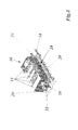
- Fig. 1 is a perspective view of a turbogenerator with in the Base frame integrated cooling air chambers according to a preferred embodiment represented the invention.
- the turbogenerator 10 is without the rotor rotatable about the rotor axis (11 in FIG. 6), without the rotor bearings (23, 24 in FIG Fig. 3) and without the outer shell shown.
- the turbogenerator 10 includes a stable, rectangular, in the direction of the rotor axis elongated base frame 14, on the several in the axial direction one behind the other, box-shaped cold air chambers 15 are arranged.
- the cold air chambers 15 enclose a hollow cylindrical or polygonal stator 12 (see also Figs.
- each other spaced cold air chambers 15 are interconnected by a plurality of axially extending tubes 19 connected (see also Fig. 6). But it is also conceivable, the cold air chambers 15 by integrated in the base frame 14 channels connect to. As can be seen from FIG. 5, cooled air is released from coolers 28 via inlets 33 by arranged on the ends of the rotor 32 fans Sucked 35 and pressed, inter alia, in the outer two cold air chambers 15, from where they are on the pipes 19 also to the internal cold air chambers arrives. In the outer cold air chambers flows around and cools the cold air Winding heads of the stator winding, which protrude from the laminated stator core.
- the cold air chambers 15 now form an integral part of the base frame 14.
- FIGS. 1, 2 and the representation of a Cross-section through a cold air chamber 15 of FIG. 6 shows the cold air chambers 15 along a horizontal middle plane each into a separate Upper part 15a and a separate lower part 15b divided.
- the lower part 15b is a integral to the basic framework and will be down to through the Base frame 14 completed (Fig. 6).
- the upper part 15a is connected to the lower part 15b is preferably detachably connected via a flange connection and forms together with the lower part 15b a closed cold air chamber 15th
- the base frame 14 Directly above the base frame 14 are on the long sides of the turbogenerator 10 outside two opposite axial channels 20, 20 'are provided, which connect the areas of the two rotor bearings (23, 24 in Fig. 3) with each other.
- These channels can be oil lines (26 in Fig. 4 and 8) for the oil supply of the Bearings 23, 24 and signal cables and power cables laid for instrumentation be without additional basic measures on the base frame 14 itself must be taken.
- the channels outside the base frame 14 they are separated from the actual machine, which in case Leakage in the oil lines prevents oil from entering the machine area immediately penetrates. Since the channels 20, 20 'are retracted inwards, they will - As Fig. 4 and Fig.
- the cold air chambers 15 integrated in the base frame 14 result in a standard configuration composed of base frames 14 and cold air chambers 15, which can be flexibly combined in a simple manner with different outer sheaths.
- a sound-absorbing or acoustic casing 21 is provided, which extends over the entire length of the base frame 14 and the Turbogenerator 10 fully enveloped above the base frame 14.
- the two bearings of the rotor 32 namely the DE bearing 23 at the driven end ( D riven E nd DE) of the rotor, and the NDE bearing 24 at the non-driven end ( N on D riven E nd NDE) of rotor.
- corresponding enclosed storage spaces 30, 31 are formed in the area of the bearings 23, 24, which are connected to one another in a pressure-compensating manner by means of the abovementioned channels 20, 20 '. Therefore, only one of these storage rooms 30, 31 must be in communication with the outside world.
- the exciter device 34 of the turbogenerator 10 is housed (Fig. 5).
- a medium-voltage space 25 is separated within the casing 21 in which medium-voltage devices can be accommodated.
- a cooler space 22 is formed, in which the coolers 28 (FIG. 5) can be accommodated.
- the cooler 28 may also be arranged below or laterally.
- the shell 27 terminates in the axial direction at both ends The provided for the rotor bearing sections of the base frame 14. It will be therefore no storage spaces provided by the shell 27.
- the shell 27 serves in this case exclusively the deflection of the circulating through the stator Cooling air by means of Umlenk memo 37 and is therefore used as a ventilation sheath.
- the radiator 28 sit in the same place as in Fig. 3 and 5.
- Channels 20, 20 ' are provided with the function already described above.
- the integrated into the base frame 14 cold air chambers 15 have in addition to the already described advantages in the flexible adaptation of envelopes yet another Another significant advantage:
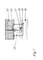
- the stable vertical outer walls 16 of the cold air chambers 15 on the longitudinal sides of the turbogenerator 10 can be used be resiliently to store the stator 12 (see Fig. 2, 6 and 7).
- At the carrying rings are laterally vertically standing, elongated spring plates 17 festgeschweisst end. Of the free middle section of the spring plates is over welded connectors 18 attached to an outer support wall.
- the invention results in a turbogenerator with a standardized Basic combination of base frame and integral cold air chambers, the can be provided in a flexible manner with different shells.
Landscapes
- Engineering & Computer Science (AREA)
- Power Engineering (AREA)
- Motor Or Generator Cooling System (AREA)
- Connection Of Motors, Electrical Generators, Mechanical Devices, And The Like (AREA)
Applications Claiming Priority (2)
| Application Number | Priority Date | Filing Date | Title |
|---|---|---|---|
| DE102004016451 | 2004-03-31 | ||
| DE200410016451 DE102004016451A1 (de) | 2004-03-31 | 2004-03-31 | Turbogenerator |
Publications (2)
| Publication Number | Publication Date |
|---|---|
| EP1583203A2 true EP1583203A2 (fr) | 2005-10-05 |
| EP1583203A3 EP1583203A3 (fr) | 2006-01-11 |
Family
ID=34877714
Family Applications (1)
| Application Number | Title | Priority Date | Filing Date |
|---|---|---|---|
| EP05102081A Withdrawn EP1583203A3 (fr) | 2004-03-31 | 2005-03-16 | Turbo-générateur |
Country Status (3)
| Country | Link |
|---|---|
| EP (1) | EP1583203A3 (fr) |
| CN (1) | CN1677800A (fr) |
| DE (1) | DE102004016451A1 (fr) |
Cited By (1)
| Publication number | Priority date | Publication date | Assignee | Title |
|---|---|---|---|---|
| EP2182611A1 (fr) * | 2008-10-28 | 2010-05-05 | Siemens Aktiengesellschaft | Agencement pour le refroidissement d'une machine électrique |
Citations (4)
| Publication number | Priority date | Publication date | Assignee | Title |
|---|---|---|---|---|
| BE646374A (fr) * | 1963-04-11 | 1964-10-12 | ||
| DE1922142A1 (de) * | 1969-04-23 | 1970-11-12 | Licentia Gmbh | Luftkuehlung einer Hilfsmaschine |
| JPH0591695A (ja) * | 1991-09-27 | 1993-04-09 | Toshiba Corp | ブラシレス回転電機 |
| DE19731313A1 (de) * | 1997-03-21 | 1998-09-24 | Siemens Ag | Großer Synchronmotor mit veränderbarer Drehzahl |
Family Cites Families (8)
| Publication number | Priority date | Publication date | Assignee | Title |
|---|---|---|---|---|
| DE532315C (de) * | 1927-06-20 | 1931-08-28 | Aeg | Staender fuer elektrische Maschinen von sehr grossen Aussenmassen, der zum Einhaltendes fuer den Eisenbahntransport vorgeschriebenen Ladeprofils zerlegt werden kann |
| US3652881A (en) * | 1970-10-15 | 1972-03-28 | Gen Electric | Generator ventilation dome and cooler casing construction |
| DE4322268A1 (de) * | 1993-07-05 | 1995-01-12 | Abb Management Ag | Horizontalachsige elektrische Maschine |
| DE19645272A1 (de) * | 1996-11-02 | 1998-05-07 | Asea Brown Boveri | Gasgekühlte elektrische Maschine |
| DE19843529A1 (de) * | 1998-09-23 | 2000-03-30 | Abb Patent Gmbh | Turbogenerator mit einem Generatorgehäuse und einem Einbaustator |
| WO2002071577A1 (fr) * | 2001-03-07 | 2002-09-12 | Hitachi, Ltd. | Machine electrique rotative |
| US6657357B2 (en) * | 2001-05-23 | 2003-12-02 | General Electric Company | Low pressure drop lattice area reinforcement for section plate support for cores of generators |
| JP4442070B2 (ja) * | 2001-09-21 | 2010-03-31 | 株式会社日立製作所 | 回転電機 |
-
2004
- 2004-03-31 DE DE200410016451 patent/DE102004016451A1/de not_active Withdrawn
-
2005
- 2005-03-16 EP EP05102081A patent/EP1583203A3/fr not_active Withdrawn
- 2005-03-31 CN CN 200510071633 patent/CN1677800A/zh active Pending
Patent Citations (4)
| Publication number | Priority date | Publication date | Assignee | Title |
|---|---|---|---|---|
| BE646374A (fr) * | 1963-04-11 | 1964-10-12 | ||
| DE1922142A1 (de) * | 1969-04-23 | 1970-11-12 | Licentia Gmbh | Luftkuehlung einer Hilfsmaschine |
| JPH0591695A (ja) * | 1991-09-27 | 1993-04-09 | Toshiba Corp | ブラシレス回転電機 |
| DE19731313A1 (de) * | 1997-03-21 | 1998-09-24 | Siemens Ag | Großer Synchronmotor mit veränderbarer Drehzahl |
Cited By (2)
| Publication number | Priority date | Publication date | Assignee | Title |
|---|---|---|---|---|
| EP2182611A1 (fr) * | 2008-10-28 | 2010-05-05 | Siemens Aktiengesellschaft | Agencement pour le refroidissement d'une machine électrique |
| US8129877B2 (en) | 2008-10-28 | 2012-03-06 | Siemens Aktiengesellschaft | Arrangement for cooling of an electrical machine |
Also Published As
| Publication number | Publication date |
|---|---|
| DE102004016451A1 (de) | 2005-11-03 |
| CN1677800A (zh) | 2005-10-05 |
| EP1583203A3 (fr) | 2006-01-11 |
Similar Documents
| Publication | Publication Date | Title |
|---|---|---|
| DE102010014649B4 (de) | Selbstfahrender Oberflächenfräser mit elektrischem Fräswalzenantrieb | |
| EP0643465B1 (fr) | Machine électrique rotative refroidi par air | |
| DE102011056007B4 (de) | Kühlsystem für eine rotierende elektrische Maschine höchster Leistungsdichte | |
| EP3108788B1 (fr) | Appareil de nettoyage par aspiration | |
| DE29724214U1 (de) | Gondelartig anzuordnender Schiffsantrieb mit Synchronmotor | |
| DE102004018758A1 (de) | Turmkopf einer Windenergieanlage | |
| EP0493704A1 (fr) | Moteur électrique | |
| CH391868A (de) | Elektrischer Generator mit direkter Leiterkühlung der Ständer-und Läuferwicklung | |
| EP0840426A1 (fr) | Machine électrique refroidie au gaz | |
| DE102010001437B4 (de) | Dynamoelektrische Maschine mit einem Schleifringläufer und geschlossener Schleifringanordnung | |
| EP0639883A1 (fr) | Machine électrique refroidie par un gaz | |
| DE1538797A1 (de) | Tauchfaehiger Elektromotor aus mehreren Einheiten | |
| EP1574714B1 (fr) | Unité de pompage | |
| CH372743A (de) | Elektrische Maschine mit waagrechter Welle | |
| DE3247888A1 (de) | Antrieb eines langsam laufenden ringfoermigen rotors einer arbeitsmaschine durch einen elektrischen motor | |
| DE19515260A1 (de) | Vertikalachsige elektrische Wasserkraftmaschine | |
| DE3424497C2 (fr) | ||
| EP1583203A2 (fr) | Turbo-générateur | |
| DE102016005380B4 (de) | Elektromaschine mit Wasser- und Luftkühlung | |
| DE1033322B (de) | Gaskuehlsystem fuer dynamoelektrische Maschinen | |
| DE19608286B4 (de) | Belüftungssystem für den Ringmotor einer Rohrmühle | |
| DE102006006839B4 (de) | Elektrische Maschine (Generator oder Motor) | |
| DE60013690T2 (de) | Brennkraftmaschine-Generator-Baueinheit | |
| DE60021471T2 (de) | Brennkraftmaschine-Generator-Baueinheit | |
| DE102006025487A1 (de) | Dynamoelektrische Maschine mit einem bürstenlosen Erreger |
Legal Events
| Date | Code | Title | Description |
|---|---|---|---|
| PUAI | Public reference made under article 153(3) epc to a published international application that has entered the european phase |
Free format text: ORIGINAL CODE: 0009012 |
|
| AK | Designated contracting states |
Kind code of ref document: A2 Designated state(s): AT BE BG CH CY CZ DE DK EE ES FI FR GB GR HU IE IS IT LI LT LU MC NL PL PT RO SE SI SK TR |
|
| AX | Request for extension of the european patent |
Extension state: AL BA HR LV MK YU |
|
| PUAL | Search report despatched |
Free format text: ORIGINAL CODE: 0009013 |
|
| AK | Designated contracting states |
Kind code of ref document: A3 Designated state(s): AT BE BG CH CY CZ DE DK EE ES FI FR GB GR HU IE IS IT LI LT LU MC NL PL PT RO SE SI SK TR |
|
| AX | Request for extension of the european patent |
Extension state: AL BA HR LV MK YU |
|
| 17P | Request for examination filed |
Effective date: 20060706 |
|
| AKX | Designation fees paid |
Designated state(s): DE FR IT |
|
| 17Q | First examination report despatched |
Effective date: 20070308 |
|
| GRAP | Despatch of communication of intention to grant a patent |
Free format text: ORIGINAL CODE: EPIDOSNIGR1 |
|
| STAA | Information on the status of an ep patent application or granted ep patent |
Free format text: STATUS: THE APPLICATION IS DEEMED TO BE WITHDRAWN |
|
| 18D | Application deemed to be withdrawn |
Effective date: 20110809 |