EP1582712A1 - Vorrichtung zum Einbringen von Kraftstoff in einen Abgasstrang - Google Patents
Vorrichtung zum Einbringen von Kraftstoff in einen Abgasstrang Download PDFInfo
- Publication number
- EP1582712A1 EP1582712A1 EP05101598A EP05101598A EP1582712A1 EP 1582712 A1 EP1582712 A1 EP 1582712A1 EP 05101598 A EP05101598 A EP 05101598A EP 05101598 A EP05101598 A EP 05101598A EP 1582712 A1 EP1582712 A1 EP 1582712A1
- Authority
- EP
- European Patent Office
- Prior art keywords
- nozzle
- injection nozzle
- injection
- nozzle carrier
- coolant circuit
- Prior art date
- Legal status (The legal status is an assumption and is not a legal conclusion. Google has not performed a legal analysis and makes no representation as to the accuracy of the status listed.)
- Granted
Links
Images


Classifications
-
- F—MECHANICAL ENGINEERING; LIGHTING; HEATING; WEAPONS; BLASTING
- F01—MACHINES OR ENGINES IN GENERAL; ENGINE PLANTS IN GENERAL; STEAM ENGINES
- F01N—GAS-FLOW SILENCERS OR EXHAUST APPARATUS FOR MACHINES OR ENGINES IN GENERAL; GAS-FLOW SILENCERS OR EXHAUST APPARATUS FOR INTERNAL-COMBUSTION ENGINES
- F01N3/00—Exhaust or silencing apparatus having means for purifying, rendering innocuous, or otherwise treating exhaust
- F01N3/08—Exhaust or silencing apparatus having means for purifying, rendering innocuous, or otherwise treating exhaust for rendering innocuous
- F01N3/10—Exhaust or silencing apparatus having means for purifying, rendering innocuous, or otherwise treating exhaust for rendering innocuous by thermal or catalytic conversion of noxious components of exhaust
- F01N3/18—Exhaust or silencing apparatus having means for purifying, rendering innocuous, or otherwise treating exhaust for rendering innocuous by thermal or catalytic conversion of noxious components of exhaust characterised by methods of operation; Control
- F01N3/20—Exhaust or silencing apparatus having means for purifying, rendering innocuous, or otherwise treating exhaust for rendering innocuous by thermal or catalytic conversion of noxious components of exhaust characterised by methods of operation; Control specially adapted for catalytic conversion
- F01N3/206—Adding periodically or continuously substances to exhaust gases for promoting purification, e.g. catalytic material in liquid form, NOx reducing agents
- F01N3/2066—Selective catalytic reduction [SCR]
-
- F—MECHANICAL ENGINEERING; LIGHTING; HEATING; WEAPONS; BLASTING
- F01—MACHINES OR ENGINES IN GENERAL; ENGINE PLANTS IN GENERAL; STEAM ENGINES
- F01N—GAS-FLOW SILENCERS OR EXHAUST APPARATUS FOR MACHINES OR ENGINES IN GENERAL; GAS-FLOW SILENCERS OR EXHAUST APPARATUS FOR INTERNAL-COMBUSTION ENGINES
- F01N3/00—Exhaust or silencing apparatus having means for purifying, rendering innocuous, or otherwise treating exhaust
- F01N3/02—Exhaust or silencing apparatus having means for purifying, rendering innocuous, or otherwise treating exhaust for cooling, or for removing solid constituents of, exhaust
- F01N3/021—Exhaust or silencing apparatus having means for purifying, rendering innocuous, or otherwise treating exhaust for cooling, or for removing solid constituents of, exhaust by means of filters
- F01N3/023—Exhaust or silencing apparatus having means for purifying, rendering innocuous, or otherwise treating exhaust for cooling, or for removing solid constituents of, exhaust by means of filters using means for regenerating the filters, e.g. by burning trapped particles
- F01N3/025—Exhaust or silencing apparatus having means for purifying, rendering innocuous, or otherwise treating exhaust for cooling, or for removing solid constituents of, exhaust by means of filters using means for regenerating the filters, e.g. by burning trapped particles using fuel burner or by adding fuel to exhaust
- F01N3/0253—Exhaust or silencing apparatus having means for purifying, rendering innocuous, or otherwise treating exhaust for cooling, or for removing solid constituents of, exhaust by means of filters using means for regenerating the filters, e.g. by burning trapped particles using fuel burner or by adding fuel to exhaust adding fuel to exhaust gases
-
- F—MECHANICAL ENGINEERING; LIGHTING; HEATING; WEAPONS; BLASTING
- F01—MACHINES OR ENGINES IN GENERAL; ENGINE PLANTS IN GENERAL; STEAM ENGINES
- F01N—GAS-FLOW SILENCERS OR EXHAUST APPARATUS FOR MACHINES OR ENGINES IN GENERAL; GAS-FLOW SILENCERS OR EXHAUST APPARATUS FOR INTERNAL-COMBUSTION ENGINES
- F01N3/00—Exhaust or silencing apparatus having means for purifying, rendering innocuous, or otherwise treating exhaust
- F01N3/02—Exhaust or silencing apparatus having means for purifying, rendering innocuous, or otherwise treating exhaust for cooling, or for removing solid constituents of, exhaust
- F01N3/021—Exhaust or silencing apparatus having means for purifying, rendering innocuous, or otherwise treating exhaust for cooling, or for removing solid constituents of, exhaust by means of filters
- F01N3/023—Exhaust or silencing apparatus having means for purifying, rendering innocuous, or otherwise treating exhaust for cooling, or for removing solid constituents of, exhaust by means of filters using means for regenerating the filters, e.g. by burning trapped particles
- F01N3/029—Exhaust or silencing apparatus having means for purifying, rendering innocuous, or otherwise treating exhaust for cooling, or for removing solid constituents of, exhaust by means of filters using means for regenerating the filters, e.g. by burning trapped particles by adding non-fuel substances to exhaust
-
- F—MECHANICAL ENGINEERING; LIGHTING; HEATING; WEAPONS; BLASTING
- F01—MACHINES OR ENGINES IN GENERAL; ENGINE PLANTS IN GENERAL; STEAM ENGINES
- F01N—GAS-FLOW SILENCERS OR EXHAUST APPARATUS FOR MACHINES OR ENGINES IN GENERAL; GAS-FLOW SILENCERS OR EXHAUST APPARATUS FOR INTERNAL-COMBUSTION ENGINES
- F01N3/00—Exhaust or silencing apparatus having means for purifying, rendering innocuous, or otherwise treating exhaust
- F01N3/08—Exhaust or silencing apparatus having means for purifying, rendering innocuous, or otherwise treating exhaust for rendering innocuous
- F01N3/10—Exhaust or silencing apparatus having means for purifying, rendering innocuous, or otherwise treating exhaust for rendering innocuous by thermal or catalytic conversion of noxious components of exhaust
- F01N3/105—General auxiliary catalysts, e.g. upstream or downstream of the main catalyst
- F01N3/106—Auxiliary oxidation catalysts
-
- F—MECHANICAL ENGINEERING; LIGHTING; HEATING; WEAPONS; BLASTING
- F01—MACHINES OR ENGINES IN GENERAL; ENGINE PLANTS IN GENERAL; STEAM ENGINES
- F01N—GAS-FLOW SILENCERS OR EXHAUST APPARATUS FOR MACHINES OR ENGINES IN GENERAL; GAS-FLOW SILENCERS OR EXHAUST APPARATUS FOR INTERNAL-COMBUSTION ENGINES
- F01N2260/00—Exhaust treating devices having provisions not otherwise provided for
- F01N2260/02—Exhaust treating devices having provisions not otherwise provided for for cooling the device
- F01N2260/024—Exhaust treating devices having provisions not otherwise provided for for cooling the device using a liquid
-
- F—MECHANICAL ENGINEERING; LIGHTING; HEATING; WEAPONS; BLASTING
- F01—MACHINES OR ENGINES IN GENERAL; ENGINE PLANTS IN GENERAL; STEAM ENGINES
- F01N—GAS-FLOW SILENCERS OR EXHAUST APPARATUS FOR MACHINES OR ENGINES IN GENERAL; GAS-FLOW SILENCERS OR EXHAUST APPARATUS FOR INTERNAL-COMBUSTION ENGINES
- F01N2530/00—Selection of materials for tubes, chambers or housings
- F01N2530/02—Corrosion resistive metals
- F01N2530/04—Steel alloys, e.g. stainless steel
-
- F—MECHANICAL ENGINEERING; LIGHTING; HEATING; WEAPONS; BLASTING
- F01—MACHINES OR ENGINES IN GENERAL; ENGINE PLANTS IN GENERAL; STEAM ENGINES
- F01N—GAS-FLOW SILENCERS OR EXHAUST APPARATUS FOR MACHINES OR ENGINES IN GENERAL; GAS-FLOW SILENCERS OR EXHAUST APPARATUS FOR INTERNAL-COMBUSTION ENGINES
- F01N2610/00—Adding substances to exhaust gases
- F01N2610/03—Adding substances to exhaust gases the substance being hydrocarbons, e.g. engine fuel
-
- F—MECHANICAL ENGINEERING; LIGHTING; HEATING; WEAPONS; BLASTING
- F01—MACHINES OR ENGINES IN GENERAL; ENGINE PLANTS IN GENERAL; STEAM ENGINES
- F01N—GAS-FLOW SILENCERS OR EXHAUST APPARATUS FOR MACHINES OR ENGINES IN GENERAL; GAS-FLOW SILENCERS OR EXHAUST APPARATUS FOR INTERNAL-COMBUSTION ENGINES
- F01N2610/00—Adding substances to exhaust gases
- F01N2610/11—Adding substances to exhaust gases the substance or part of the dosing system being cooled
-
- F—MECHANICAL ENGINEERING; LIGHTING; HEATING; WEAPONS; BLASTING
- F01—MACHINES OR ENGINES IN GENERAL; ENGINE PLANTS IN GENERAL; STEAM ENGINES
- F01N—GAS-FLOW SILENCERS OR EXHAUST APPARATUS FOR MACHINES OR ENGINES IN GENERAL; GAS-FLOW SILENCERS OR EXHAUST APPARATUS FOR INTERNAL-COMBUSTION ENGINES
- F01N2610/00—Adding substances to exhaust gases
- F01N2610/14—Arrangements for the supply of substances, e.g. conduits
- F01N2610/1453—Sprayers or atomisers; Arrangement thereof in the exhaust apparatus
-
- F—MECHANICAL ENGINEERING; LIGHTING; HEATING; WEAPONS; BLASTING
- F02—COMBUSTION ENGINES; HOT-GAS OR COMBUSTION-PRODUCT ENGINE PLANTS
- F02M—SUPPLYING COMBUSTION ENGINES IN GENERAL WITH COMBUSTIBLE MIXTURES OR CONSTITUENTS THEREOF
- F02M63/00—Other fuel-injection apparatus having pertinent characteristics not provided for in groups F02M39/00 - F02M57/00 or F02M67/00; Details, component parts, or accessories of fuel-injection apparatus, not provided for in, or of interest apart from, the apparatus of groups F02M39/00 - F02M61/00 or F02M67/00; Combination of fuel pump with other devices, e.g. lubricating oil pump
- F02M63/02—Fuel-injection apparatus having several injectors fed by a common pumping element, or having several pumping elements feeding a common injector; Fuel-injection apparatus having provisions for cutting-out pumps, pumping elements, or injectors; Fuel-injection apparatus having provisions for variably interconnecting pumping elements and injectors alternatively
- F02M63/0225—Fuel-injection apparatus having a common rail feeding several injectors ; Means for varying pressure in common rails; Pumps feeding common rails
-
- Y—GENERAL TAGGING OF NEW TECHNOLOGICAL DEVELOPMENTS; GENERAL TAGGING OF CROSS-SECTIONAL TECHNOLOGIES SPANNING OVER SEVERAL SECTIONS OF THE IPC; TECHNICAL SUBJECTS COVERED BY FORMER USPC CROSS-REFERENCE ART COLLECTIONS [XRACs] AND DIGESTS
- Y02—TECHNOLOGIES OR APPLICATIONS FOR MITIGATION OR ADAPTATION AGAINST CLIMATE CHANGE
- Y02A—TECHNOLOGIES FOR ADAPTATION TO CLIMATE CHANGE
- Y02A50/00—TECHNOLOGIES FOR ADAPTATION TO CLIMATE CHANGE in human health protection, e.g. against extreme weather
- Y02A50/20—Air quality improvement or preservation, e.g. vehicle emission control or emission reduction by using catalytic converters
-
- Y—GENERAL TAGGING OF NEW TECHNOLOGICAL DEVELOPMENTS; GENERAL TAGGING OF CROSS-SECTIONAL TECHNOLOGIES SPANNING OVER SEVERAL SECTIONS OF THE IPC; TECHNICAL SUBJECTS COVERED BY FORMER USPC CROSS-REFERENCE ART COLLECTIONS [XRACs] AND DIGESTS
- Y02—TECHNOLOGIES OR APPLICATIONS FOR MITIGATION OR ADAPTATION AGAINST CLIMATE CHANGE
- Y02T—CLIMATE CHANGE MITIGATION TECHNOLOGIES RELATED TO TRANSPORTATION
- Y02T10/00—Road transport of goods or passengers
- Y02T10/10—Internal combustion engine [ICE] based vehicles
- Y02T10/12—Improving ICE efficiencies
Definitions
- the present invention relates to a device for Introducing fuel into an exhaust line of a Internal combustion engine, in particular in a motor vehicle, with the features of the preamble of claim 1.
- Such a device is for example from the DE 30 46 258 Al known and comprises an injection nozzle for Injecting fuel under injection pressure in the exhaust line through a radial opening in one Pipe section of the exhaust system.
- a particle filter to arrange.
- Such a particle filter is usually Also referred to as soot filter, since it is in the exhaust entrained particles, especially in diesel engines, predominantly is soot.
- soot filter In operation of the internal combustion engine the filtered out particles accumulate in the respective one Particle filter, which gradually to a back pressure increase at the flow through the particulate filter leads. Accordingly, it is common for the particulate filter to be regular subjecting it to a regeneration process in which the deposited particles are burned off. To such a Combustion reaction for regeneration of the particulate filter To be able to initiate the temperature in the particle filter or increased in the exhaust gas supplied to the particulate filter become.
- such a temperature increase in Exhaust gas can be realized by engine-side measures.
- additional fuel so late in the combustion chambers of the Internal combustion engine to be injected, that this is not burns more, leaving unburned fuel in the Exhaust line arrives.
- Upstream of the particulate filter is then expediently arranged an oxidation catalyst having a Implementation of the additionally injected fuel quantity causes. This results in a highly exothermic Reaction, what the desired temperature increase in the exhaust gas causes.
- the present invention deals with the problem for a device of the type mentioned a to provide improved embodiment, in particular characterized by an increased life.
- the invention is based on the general idea that To cool the injection nozzle.
- By cooling the injector may be that of the injector during operation of the internal combustion engine heat dissipated via the exhaust gas line, causing the injector at a temperature level can be operated, which is considerably below the Temperature levels of the exhaust system is.
- This has many advantages.
- the Material stress within the injector thereby reduced, giving it an increased life.
- To the others are at risk of self - ignition Fuel within the injector significantly reduced.
- a valve may be relatively close to the injector at a nozzle head having at least one injection hole be positioned, resulting in a dead volume Fuel that is between the at least one Spray hole and said valve is reduced.
- At uncooled injectors must be a relatively large distance between the at least one spray hole and said Valve to be respected by the high temperatures not impairing the functionality of the valve.
- the dead volume of fuel In the sequence increases in an uncooled Injector the dead volume of fuel. The bigger this one Dead volume is, the more inaccurate is the additional Feed the fuel feed into the exhaust line. Accordingly, the cooled injector ultimately leads also to an improved metering of the additional injected fuel.
- the cooling of the injection nozzle according to the invention with the help a coolant circuit causes, which in a suitable manner with the injection nozzle is coupled to transmit heat.
- expedient can a section of this coolant circuit in the Injector be integrated. This way a can realized particularly intensive cooling of the injection nozzle become.
- the Injector be attached to a nozzle carrier, the in turn attached to the pipe section, in which case the Nozzle carrier with the coolant circuit heat transfer is coupled, so that the injector indirectly through or via the nozzle carrier with the coolant circuit is coupled heat-transmitting.
- this construction is thus the nozzle carrier directly through the coolant circuit cooled, while the attached injector only indirectly via the nozzle carrier through the coolant circuit is cooled.
- This construction has the advantage that a conventional, so inexpensive injector can be used can, so that the nozzle carrier quasi a kind of adapter for Realization of a cooling of the injection nozzle represents.
- the nozzle carrier intensive cooling for the Injection nozzle can be realized.
- the Nozzle holder containing a nozzle holder, the Nozzle carrier penetrated at least radially and in the Radial opening of the pipe section opens open, in which case the injector is inserted into this nozzle holder, so that contains at least one injection hole Nozzle head of the injection nozzle in the area of the radial opening located.
- the injection nozzle within the nozzle receptacle transverse to its longitudinal direction completely enclosed by the nozzle holder, up to her nozzle head. In this way can be an intensive cooling the injection nozzle can be realized, since the nozzle carrier along a relatively large surface with the Injection nozzle is contactable.
- Also preferred here is a variant in which a Section of the coolant circuit in the nozzle carrier integrated, resulting in a particularly effective Cooling of the nozzle carrier and thus of the injection nozzle can achieve.
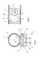
- an inventive Device 1 an injection nozzle 2 and is so on a Pipe section 3 of an exhaust line 4 one in Fig. 4th shown internal combustion engine 5 arranged that the Injector 2 fuel through a radial opening 5 in the Inject or squirt exhaust system 4, which in the Pipe section 3 is formed.
- Fig. 1 is a with help the injection nozzle 2 producible spray or spray jet indicated and designated 6.
- the injection nozzle 2 is electrically controllable and adjustable designed.
- the injection nozzle 2 is cooled.
- a coolant circuit 7 with which the injection nozzle 2 is coupled heat transfer.
- a suitable cooling medium preferably a cooling liquid.
- the injection nozzle 2 directly with to couple the coolant circuit 7 heat transfer. Especially it is then advantageous to use a section of the Integrate coolant circuit 7 in the injection nozzle 2.
- the embodiment shown here is preferred which the injection nozzle 2 indirectly with the coolant circuit 7 is coupled heat transfer.
- the Device 1 a nozzle carrier 8, which is on the pipe section 3 is attached.
- this nozzle carrier 8 is on the pipe section 3 welded.
- Appropriate welds can be seen in Fig. 2 and designated 9.
- the injection nozzle 2 is now attached.
- the coolant circuit 7 for direct cooling of the nozzle carrier. 8 and thus for indirect cooling of the injection nozzle 2 via or through the nozzle carrier 8.
- the coolant circuit 7 heat-transmitting with the nozzle carrier. 8 coupled.
- the injection nozzle 2 is on Nozzle holder 8 attached, that also a possible can set intense heat transfer.
- the nozzle carrier 8 has a nozzle holder 10, which is substantially complementary to the injection nozzle. 2 is formed and which passes through the nozzle carrier 8 radially.
- the injection nozzle 2 is now in this nozzle holder 10th used, in particular inserted or screwed.
- the Nozzle holder 10 is designed so that a Nozzle head 12 of the inserted into the nozzle holder 10 Injector 2 is located in the region of the radial opening 5.
- the means, the nozzle head 12 is located within the Mouth end 11 or protrudes above it, as in FIG. 1.
- This nozzle head 12 includes at least one injection hole, through the fuel in the interior of the pipe section. 3 can be injected or injected.
- the complementary complementary is formed to the outer contour with the injection nozzle 2, can a particularly large contact between Injector 2 and nozzle carrier 8 can be achieved, which the Heat transfer between injector 2 and nozzle carrier 8 improved.
- a nozzle holder leads 10 in which the injection nozzle 2 with a substantial Longitudinal section is used, inevitably to the fact that the Nozzle carrier 8, the injection nozzle 2 in the in the Nozzle holder 10 inserted longitudinal section circumferentially completely encloses, which is a particularly intense Thermal coupling allows.
- the nozzle carrier 8 made of a material be prepared, which has a relatively high thermal conductivity has.
- the nozzle carrier 8 is made of steel manufactured to easily the relatively high temperatures the exhaust line 4 to be able to withstand.
- the nozzle holder 8 made of a stainless steel to the aggressive, especially corrosive, environment of Exhaust system 4. It is the same basically possible, the nozzle carrier 8 from another reactorleitmaterial, such as. As copper or brass, manufacture.
- the nozzle carrier 8 is also an integral construction, in which the nozzle carrier 8 is made in one piece. This allows insulating transition zones, which in a built nozzle carrier 8 can be avoided.
- Coolant circuit 7 in the nozzle carrier. 8 integrated. This partial integration of the Coolant circuit 7 in the nozzle carrier 8 leads to a particularly effective cooling of the nozzle carrier 8 and thus the heat transfer coupled injection nozzle. 2
- the nozzle carrier is the eighth on a side facing the pipe section 3 preferably equipped with a plug-in section 16 in the Radial opening 5 of the pipe section 3 penetrates or is used.
- the plug-in section 16 is expedient shaped circumferentially complementary to the radial opening 5, whereby the plug portion 16 in the installed state the Radial opening 5 more or less fills.
- this Plug portion 16 is the mouth end 11 of the nozzle holder 10 arranged. Due to the selected inclination of the nozzle holder 10 with respect to a radial plane receives the mouth end 11 at the interior of the pipe section 3 facing end face the plug section the shape of a slot, which is shown in FIG. 3 is removable.
- the device 1 according to the invention serves for introducing Fuel in the exhaust line 4 of the internal combustion engine 5, which may be arranged in particular in a motor vehicle can.
- the pipe section 3, on in which the device 1 is attached to the exhaust line 4 be arranged upstream of an oxidation catalyst 17, which in turn upstream of a particulate filter 18th located.
- the particle filter 18 serves to particles, which be carried in the exhaust gases of the internal combustion engine 5, to filter out of these exhaust gases.
- This fuel gets into the Oxidation catalyst 17, in which it is reacted. in this connection Heat is released, which increases the temperature of the exhaust gas. As a result, it comes in the particulate filter 18 to a Temperature increase. At a sufficiently high temperature is in the particulate filter 18, a burning of the particles, at which are preferably soot particles, initiated. The initiated burning process can then continue to run independently, as he also under delivery of Heat expires. This means that after the initiation of the Burning process the injection of the fuel with the help of Device 1 can be stopped.
- Fig. 4 shows a preferred embodiment in which the coolant circuit 7, with the aid of the injection nozzle. 2 is cooled, to a cooling circuit 19 of the internal combustion engine. 5 connected.
- This cooling circuit 19 serves to cool the Internal combustion engine 5 and includes a corresponding radiator 20, which can be acted upon by a blower 21 in the rule is. The effort to realize the cooling of Injector 2 is thereby significantly reduced because so far no completely independent cooling system is required.
- a modern internal combustion engine 5, in particular a Diesel engine is usually with one Fuel supply system 22 equipped after the so-called “common rail principle” works. Includes the fuel supply system 22 at least one common Fuel high-pressure line 23, the parallel several, Preferably, all, injectors 24 of the Internal combustion engine 5 with high pressure standing Fuel supplied.
- the high pressure line 23 in turn fed by an injection pump 25 which is connected to a Fuel reservoir 26, so to a fuel tank, connected.
- the injectors 24 of the Internal combustion engine 5 are used in a conventional manner for Injecting fuel into the combustion chambers of the Internal combustion engine 5.
- the injection nozzle 2 of the Device 1 according to the invention to an additional fuel supply system 27 connected by the Fuel supply system 22 of the internal combustion engine 5 is independent.
- such contains Additional fuel supply system 27 a suitable pump 28, which generates the required injection pressure.
- the additional fuel supply system 27 and its Pump 28 also to the fuel reservoir 26th connected.
- the Injector 2 of the device 1 according to the invention also the high pressure line 23 of the fuel supply system 22nd be connected to the internal combustion engine 5.
- a conventional To use injection nozzle 2 e.g. a Gasoline direct injection nozzle, which is normally in the Combustion chamber protrudes.
- a can also Injection nozzle 2 are used, the otherwise to Injecting fuel into a combustion chamber of the Internal combustion engine 5 is used.
- the Injector 2 of the device 1 thus identical to a the injection nozzles 24 of the internal combustion engine 5 be.
Landscapes
- Engineering & Computer Science (AREA)
- Chemical & Material Sciences (AREA)
- Combustion & Propulsion (AREA)
- Mechanical Engineering (AREA)
- General Engineering & Computer Science (AREA)
- Chemical Kinetics & Catalysis (AREA)
- Materials Engineering (AREA)
- Health & Medical Sciences (AREA)
- Toxicology (AREA)
- Fuel-Injection Apparatus (AREA)
Abstract
Description
- Fig. 1
- einen stark vereinfachten Längsschnitt durch eine Vorrichtung nach der Erfindung,
- Fig. 2
- einen Querschnitt der Vorrichtung entsprechend Schnittlinien II in Fig. 1,
- Fig. 3
- eine geschnittene Draufsicht entsprechend Schnittlinien III in Fig. 1,
- Fig. 4
- eine schaltplanartige Prinzipdarstellung für eine Anordnung der erfindungsgemäßen Vorrichtung bei einer Brennkraftmaschine.
Claims (12)
- Vorrichtung zum Einbringen von Kraftstoff in einen Abgasstrang (4) einer Brennkraftmaschine (5), insbesondere in einem Kraftfahrzeug, mit einer Einspritzdüse (2) zum Einspritzen von unter Einspritzdruck stehendem Kraftstoff in den Abgasstrang (4) durch eine Radialöffnung (5) in einem Rohrabschnitt (3) des Abgasstrangs (4),
dadurch gekennzeichnet, dass die Einspritzdüse (2) mit einem Kühlmittelkreis (7) wärmeübertragend gekoppelt ist. - Vorrichtung nach Anspruch 1,
dadurch gekennzeichnet, dass ein Abschnitt des Kühlmittelkreises (7) in die Einspritzdüse (2) integriert ist. - Vorrichtung nach Anspruch 1,
dadurch gekennzeichnet,dass die Einspritzdüse (2) an einem Düsenträger (8) befestigt ist, der seinerseits am Rohrabschnitt (3) befestigt ist,dass der Düsenträger (8) mit dem Kühlmittelkreis (7) wärmeübertragend gekoppelt ist, so dass die Einspritzdüse (2) mittelbar durch oder über den Düsenträger (8) mit dem Kühlmittelkreis (7) wärmeübertragend gekoppelt ist. - Vorrichtung nach Anspruch 3,
dadurch gekennzeichnet,dass der Düsenträger (8) eine Düsenaufnahme (10) enthält, die den Düsenträger (8) radial durchsetzt und in der Radialöffnung (5) des Rohrabschnitts (3) offen mündet,dass die Einspritzdüse (2) in die Düsenaufnahme (10) eingesetzt ist, so dass sich ein Düsenkopf (12) der Einspritzdüse (2) im Bereich der Radialöffnung (5) befindet. - Vorrichtung nach Anspruch 4,
dadurch gekennzeichnet, dass der Düsenträger (8) einen Steckabschnitt (16) aufweist, der in die Radialöffnung (5) des Rohrabschnitts (3) eingesetzt ist und in dem sich ein Mündungsende (11) der Düsenaufnahme (10) befindet. - Vorrichtung nach einem der Ansprüche 3 bis 5,
dadurch gekennzeichnet, dass zumindest ein Abschnitt (13) des Kühlmittelkreises (7) in den Düsenträger (8) integriert ist. - Vorrichtung nach einem der Ansprüche 3 bis 6,
dadurch gekennzeichnet, dass der Düsenträger (8) aus einem Material mit relativ hoher Wärmeleitfähigkeit hergestellt ist. - Vorrichtung nach Anspruch 7,
dadurch gekennzeichnet, dass der Düsenträger (8) aus Stahl oder Edelstahl hergestellt ist. - Vorrichtung nach einem der Ansprüche 3 bis 8,
dadurch gekennzeichnet, dass der Düsenträger (8) aus einem Stück hergestellt ist. - Vorrichtung nach einem der Ansprüche 3 bis 9,
dadurch gekennzeichnet, dass der Düsenträger (8) an den Rohrabschnitt (3) angeschweißt ist. - Vorrichtung nach einem der Ansprüche 1 bis 10,
dadurch gekennzeichnet, dass der Kühlmittelkreis (7) an einen Kühlkreis (19) der Brennkraftmaschine (5) angeschlossen ist. - Vorrichtung nach einem der Ansprüche 1 bis 11,
dadurch gekennzeichnet,dass die Einspritzdüse (2) an ein Kraftstoffversorgungssystem (22) der Brennkraftmaschine (5) angeschlossen ist, insbesondere an eine gemeinsame Kraftstoff-Hochdruckleitung (23) eines Common-Rail-Systems, oderdass die Einspritzdüse (2) an ein von einem Kraftstoffversorgungssystem (22) der Brennkraftmaschine (5) unabhängiges Zusatz-Kraftstoffversorgungssystem (27) angeschlossen ist.
Priority Applications (1)
| Application Number | Priority Date | Filing Date | Title |
|---|---|---|---|
| EP06127194A EP1775434A1 (de) | 2004-03-29 | 2005-03-02 | Abgasstrang einer Brennkraftmaschine |
Applications Claiming Priority (2)
| Application Number | Priority Date | Filing Date | Title |
|---|---|---|---|
| DE102004015805A DE102004015805B4 (de) | 2004-03-29 | 2004-03-29 | Vorrichtung zum Einbringen einer Flüssigkeit in einen Abgasstrang |
| DE102004015805 | 2004-03-29 |
Related Child Applications (1)
| Application Number | Title | Priority Date | Filing Date |
|---|---|---|---|
| EP06127194A Division EP1775434A1 (de) | 2004-03-29 | 2005-03-02 | Abgasstrang einer Brennkraftmaschine |
Publications (2)
| Publication Number | Publication Date |
|---|---|
| EP1582712A1 true EP1582712A1 (de) | 2005-10-05 |
| EP1582712B1 EP1582712B1 (de) | 2007-12-12 |
Family
ID=34877670
Family Applications (2)
| Application Number | Title | Priority Date | Filing Date |
|---|---|---|---|
| EP05101598A Ceased EP1582712B1 (de) | 2004-03-29 | 2005-03-02 | Vorrichtung zum Einbringen von Kraftstoff in einen Abgasstrang |
| EP06127194A Withdrawn EP1775434A1 (de) | 2004-03-29 | 2005-03-02 | Abgasstrang einer Brennkraftmaschine |
Family Applications After (1)
| Application Number | Title | Priority Date | Filing Date |
|---|---|---|---|
| EP06127194A Withdrawn EP1775434A1 (de) | 2004-03-29 | 2005-03-02 | Abgasstrang einer Brennkraftmaschine |
Country Status (3)
| Country | Link |
|---|---|
| US (1) | US7168241B2 (de) |
| EP (2) | EP1582712B1 (de) |
| DE (2) | DE102004015805B4 (de) |
Cited By (7)
| Publication number | Priority date | Publication date | Assignee | Title |
|---|---|---|---|---|
| WO2007078662A1 (en) * | 2005-12-29 | 2007-07-12 | Caterpillar Inc. | Nozzle assembly |
| FR2897642A1 (fr) * | 2006-02-20 | 2007-08-24 | Renault Sas | Procede et dispositif de regeneration du filtre a particules de l'echappement d'un moteur a combustion interne |
| FR2900961A1 (fr) * | 2006-05-10 | 2007-11-16 | Renault Sas | Support d'injecteur de carburant pourvu d'un noyau d'eau simplifie et ligne d'echappement comportant un tel support d'injecteur de carburant |
| EP1925790A1 (de) * | 2006-11-17 | 2008-05-28 | J. Eberspächer GmbH & Co. KG | Brennkraftmaschinensystem |
| WO2008121319A3 (en) * | 2007-03-30 | 2008-12-18 | Continental Automotive Systems | Reductant delivery unit for selective catalytic reduction |
| FR2948968A1 (fr) * | 2009-08-07 | 2011-02-11 | Peugeot Citroen Automobiles Sa | Dispositif d'injection de carburant dans une ligne d'echappement pour la regeneration d'un filtre a particules |
| EP2664760A1 (de) * | 2012-05-15 | 2013-11-20 | Toyota Jidosha Kabushiki Kaisha | Wärmeableitende Struktur eines Einspritzventils |
Families Citing this family (50)
| Publication number | Priority date | Publication date | Assignee | Title |
|---|---|---|---|---|
| BRPI0411322A (pt) * | 2003-06-12 | 2006-07-18 | Donaldson Co Inc | método de distribuir combustìvel em fluxo transiente de um sistema de descarga |
| WO2005028827A1 (ja) * | 2003-09-19 | 2005-03-31 | Nissan Diesel Motor Co., Ltd. | エンジンの排気浄化装置 |
| JP2005207289A (ja) * | 2004-01-22 | 2005-08-04 | Hino Motors Ltd | ディーゼルエンジンの排気管燃料添加方式 |
| DE102004048336A1 (de) * | 2004-10-01 | 2006-04-13 | J. Eberspächer GmbH & Co. KG | Abgasanlage für eine Brennkraftmaschine |
| DE102004056791B4 (de) * | 2004-11-24 | 2007-04-19 | J. Eberspächer GmbH & Co. KG | Abgasanlage |
| US8109076B2 (en) * | 2006-02-17 | 2012-02-07 | Renault S.A.S. | Method and device for purging an injector in a fuel injector system of use in the regeneration of a particulate filter |
| FR2897649B1 (fr) * | 2006-02-17 | 2008-05-09 | Renault Sas | Procede et dispositif de purge d'un injecteur d'un systeme d'injection de carburant d'aide a la regeneration d'un filtre a particules |
| US20070235556A1 (en) * | 2006-03-31 | 2007-10-11 | Harmon Michael P | Nozzle assembly |
| US8678300B2 (en) * | 2006-06-19 | 2014-03-25 | Continental Automotive Systems, Inc. | Automotive diesel exhaust water cooled HC dosing |
| EP2060758B1 (de) * | 2006-07-12 | 2010-10-13 | Delphi Technologies Holding S.à.r.l. | Isolierte Reagenzdosiervorrichtung |
| FR2904363A1 (fr) * | 2006-07-25 | 2008-02-01 | Renault Sas | Dispositif de depollution des gaz d'echappement d'un moteur a combustion interne |
| DE102006044080B4 (de) * | 2006-09-20 | 2023-10-12 | Robert Bosch Gmbh | Verfahren zum Betreiben eines Reagenzmittel-Dosierventils und Vorrichtung zur Durchführung des Verfahrens |
| JP4656039B2 (ja) * | 2006-10-19 | 2011-03-23 | 株式会社デンソー | エンジンの排気浄化装置 |
| WO2008052361A1 (en) * | 2006-11-03 | 2008-05-08 | Nxtgen Emission Controls Inc. | Fuel processor |
| WO2008052359A1 (en) * | 2006-11-03 | 2008-05-08 | Nxtgen Emission Controls Inc. | Liquid fuel introduction device for fuel processor |
| DE102006059507B4 (de) * | 2006-12-14 | 2016-08-25 | Eberspächer Exhaust Technology GmbH & Co. KG | Abgasanlage mit Injektor |
| DE102006062491A1 (de) * | 2006-12-28 | 2008-07-03 | Robert Bosch Gmbh | Vorrichtung zur Dosierung von Kraftstoff zum Abgassystem eines Verbrennungsmotors |
| US8453436B2 (en) * | 2007-03-08 | 2013-06-04 | Mack Trucks, Inc. | Aftertreatment injector anti-fouling device |
| WO2008144385A2 (en) * | 2007-05-15 | 2008-11-27 | Donaldson Company, Inc. | Exhaust gas flow device |
| US8056326B2 (en) * | 2007-05-31 | 2011-11-15 | Caterpillar Inc. | Regeneration device having cooled injection housing |
| JP2009097479A (ja) * | 2007-10-19 | 2009-05-07 | Bosch Corp | 還元剤供給装置の制御装置及び制御方法 |
| KR100999614B1 (ko) * | 2007-12-14 | 2010-12-08 | 기아자동차주식회사 | 배기 가스 내의 질소산화물 저감 장치 |
| DE102008052757B4 (de) * | 2008-10-22 | 2014-02-20 | Eberspächer Exhaust Technology GmbH & Co. KG | Vorrichtung zum Einbringen einer Flüssigkeit in eine Abgasströmung |
| DE102008052988B4 (de) * | 2008-10-23 | 2012-09-27 | Continental Automotive Gmbh | Verfahren und Vorrichtung zum Steuern einer Abgasnachbehandlung |
| EP2366063B1 (de) * | 2008-11-13 | 2018-09-12 | Donaldson Company, Inc. | Einspritzventilbefestigungskonfiguration für ein abgasbehandlungssystem |
| CA2684513A1 (en) * | 2008-11-17 | 2010-05-17 | X6D Limited | Improved performance 3d glasses |
| US8171722B2 (en) * | 2008-12-05 | 2012-05-08 | Caterpillar Inc. | Fluid delivery system |
| EP2358982B1 (de) * | 2008-12-17 | 2017-11-08 | Donaldson Company, Inc. | Flussvorrichtung für ein abgassystem |
| US8393154B2 (en) * | 2009-02-12 | 2013-03-12 | Pratt & Whitney Canada Corp. | Fuel delivery system with reduced heat transfer to fuel manifold seal |
| DE102009028030A1 (de) * | 2009-07-27 | 2011-02-03 | Robert Bosch Gmbh | Montageeinheit zur Befestigung eines Einspritzorgans an einem Abgasstrang und Abgasnachbehandlungsanordnung |
| JP2011080397A (ja) * | 2009-10-06 | 2011-04-21 | Bosch Corp | 内燃機関の排気浄化装置 |
| WO2011087527A1 (en) * | 2010-01-12 | 2011-07-21 | Donaldson Company, Inc. | Flow device for exhaust treatment system |
| US9670811B2 (en) | 2010-06-22 | 2017-06-06 | Donaldson Company, Inc. | Dosing and mixing arrangement for use in exhaust aftertreatment |
| US20140013728A1 (en) * | 2011-04-04 | 2014-01-16 | Mack Trucks ,Inc. | Fluid cooled injector and exhaust aftertreatment system, vehicle, and method using a fluid cooled injector |
| DE102011103119B4 (de) * | 2011-06-01 | 2024-10-10 | Mercedes-Benz Group AG | Anordnung einer Abgasanlage an einer Verbrennungskraftmaschine eines Kraftwagens und Abgasanlage |
| US8938954B2 (en) | 2012-04-19 | 2015-01-27 | Donaldson Company, Inc. | Integrated exhaust treatment device having compact configuration |
| DE102012206563A1 (de) * | 2012-04-20 | 2013-10-24 | Bayerische Motoren Werke Aktiengesellschaft | SCR-Anordnung mit kühlmittelgekühltem Dosiermodul |
| US9188084B2 (en) | 2012-10-31 | 2015-11-17 | Electro-Motive Diesel, Inc. | Fuel system having a cooled injector |
| US9188085B2 (en) | 2012-10-31 | 2015-11-17 | Electro-Motive Diesel, Inc. | Fuel system having multiple gaseous fuel injectors |
| US9500168B2 (en) * | 2012-10-31 | 2016-11-22 | Electro-Motive Diesel, Inc. | Fuel system having a fuel-cooled injector |
| US9046068B2 (en) | 2012-10-31 | 2015-06-02 | Electro-Motive Diesel, Inc. | Fuel system for a dual-fuel engine |
| US9103600B2 (en) | 2012-12-21 | 2015-08-11 | Caterpillar Inc. | Injector cooling apparatus and method |
| WO2014115461A1 (ja) * | 2013-01-25 | 2014-07-31 | フタバ産業株式会社 | 排ガス浄化装置 |
| US9334813B2 (en) | 2013-01-31 | 2016-05-10 | Electro-Motive Diesel, Inc. | Control system for a dual-fuel engine |
| EP2956233B1 (de) | 2013-02-15 | 2016-12-21 | Donaldson Company, Inc. | Dosier- und mischanordnung zur verwendung bei der abgasnachbehandlung |
| US8973355B2 (en) | 2013-03-15 | 2015-03-10 | Tenneco Automotive Operating Company Inc. | Multi-layer liquid-cooled mount |
| US9441529B2 (en) | 2013-06-27 | 2016-09-13 | Electro-Motive Diesel, Inc. | Fuel system having sealed injection port |
| EP3436752B1 (de) | 2016-03-30 | 2021-06-30 | Marine Canada Acquisition Inc. | Fahrzeugheizgerät und steuerungen dafür |
| DE102020126775B3 (de) | 2020-10-13 | 2022-01-27 | Dr. Ing. H.C. F. Porsche Aktiengesellschaft | Haltevorrichtung für ein Einspritzventil eines Abgasbrenners und Abgasbrenner |
| JP7444101B2 (ja) * | 2021-02-19 | 2024-03-06 | 株式会社豊田自動織機 | 冷却システムおよび冷却システムの制御方法 |
Citations (7)
| Publication number | Priority date | Publication date | Assignee | Title |
|---|---|---|---|---|
| DE349770C (de) * | 1922-03-07 | Eugene Henri Tartrais | Ventilzerstaeuber fuer Motoren mit Einspritzung fluessigen Brennstoffs, bei dem die Einspritzung in Form einer breiten Flaeche durch einen ringfoermigen Schlitz stattfindet | |
| DE4436397A1 (de) * | 1994-10-12 | 1996-04-18 | Bosch Gmbh Robert | Einrichtung zum Nachbehandeln von Abgasen |
| DE19581135T1 (de) * | 1994-08-23 | 1996-11-21 | Caterpillar Inc | Verbrennungsabgasreinigungssystem und Verfahren |
| JPH0996212A (ja) * | 1995-10-03 | 1997-04-08 | Mitsubishi Motors Corp | ディーゼルエンジンの排気浄化装置 |
| WO1999041492A2 (de) * | 1998-02-16 | 1999-08-19 | Siemens Aktiengesellschaft | Dosiersystem |
| WO2000066885A1 (de) * | 1999-04-28 | 2000-11-09 | Siemens Aktiengesellschaft | Ventilaufnahmevorrichtung für ein dosierventil einer abgasnachbehandlungsanlage |
| WO2003084647A1 (en) * | 2002-04-03 | 2003-10-16 | Cleaire Advanced Emission Controls, Llc. | Fluid-cooled mount for an injector |
Family Cites Families (8)
| Publication number | Priority date | Publication date | Assignee | Title |
|---|---|---|---|---|
| CH152348A (de) * | 1930-12-20 | 1932-01-31 | Dinner Heinrich | Brennstoffeinspritzvorrichtung mit gekühltem Einspritzorgan. |
| GB2064983B (en) * | 1979-12-13 | 1984-01-04 | Texaco Development Corp | Rejuvenation of an exhaust gas particulate filter |
| US6279603B1 (en) * | 1998-10-01 | 2001-08-28 | Ambac International | Fluid-cooled injector |
| DE19856366C1 (de) * | 1998-12-07 | 2000-04-20 | Siemens Ag | Vorrichtung und Verfahren zum Nachbehandeln von Abgasen einer mit Luftüberschuß arbeitenden Brennkraftmaschine |
| JP2000291429A (ja) * | 1999-04-01 | 2000-10-17 | Nippon Soken Inc | 排気系炭化水素添加装置 |
| US6615580B1 (en) * | 1999-06-23 | 2003-09-09 | Southwest Research Institute | Integrated system for controlling diesel engine emissions |
| JP2002030919A (ja) * | 2000-07-19 | 2002-01-31 | Hino Motors Ltd | 排気浄化装置 |
| KR20030096939A (ko) * | 2002-06-18 | 2003-12-31 | 현대자동차주식회사 | 디젤 엔진의 입자상 물질 제거용 필터의 재생 장치 |
-
2004
- 2004-03-29 DE DE102004015805A patent/DE102004015805B4/de not_active Expired - Fee Related
-
2005
- 2005-03-02 DE DE502005002183T patent/DE502005002183D1/de not_active Expired - Lifetime
- 2005-03-02 EP EP05101598A patent/EP1582712B1/de not_active Ceased
- 2005-03-02 EP EP06127194A patent/EP1775434A1/de not_active Withdrawn
- 2005-03-28 US US11/091,174 patent/US7168241B2/en not_active Expired - Lifetime
Patent Citations (7)
| Publication number | Priority date | Publication date | Assignee | Title |
|---|---|---|---|---|
| DE349770C (de) * | 1922-03-07 | Eugene Henri Tartrais | Ventilzerstaeuber fuer Motoren mit Einspritzung fluessigen Brennstoffs, bei dem die Einspritzung in Form einer breiten Flaeche durch einen ringfoermigen Schlitz stattfindet | |
| DE19581135T1 (de) * | 1994-08-23 | 1996-11-21 | Caterpillar Inc | Verbrennungsabgasreinigungssystem und Verfahren |
| DE4436397A1 (de) * | 1994-10-12 | 1996-04-18 | Bosch Gmbh Robert | Einrichtung zum Nachbehandeln von Abgasen |
| JPH0996212A (ja) * | 1995-10-03 | 1997-04-08 | Mitsubishi Motors Corp | ディーゼルエンジンの排気浄化装置 |
| WO1999041492A2 (de) * | 1998-02-16 | 1999-08-19 | Siemens Aktiengesellschaft | Dosiersystem |
| WO2000066885A1 (de) * | 1999-04-28 | 2000-11-09 | Siemens Aktiengesellschaft | Ventilaufnahmevorrichtung für ein dosierventil einer abgasnachbehandlungsanlage |
| WO2003084647A1 (en) * | 2002-04-03 | 2003-10-16 | Cleaire Advanced Emission Controls, Llc. | Fluid-cooled mount for an injector |
Non-Patent Citations (1)
| Title |
|---|
| PATENT ABSTRACTS OF JAPAN vol. 1997, no. 08 29 August 1997 (1997-08-29) * |
Cited By (8)
| Publication number | Priority date | Publication date | Assignee | Title |
|---|---|---|---|---|
| WO2007078662A1 (en) * | 2005-12-29 | 2007-07-12 | Caterpillar Inc. | Nozzle assembly |
| FR2897642A1 (fr) * | 2006-02-20 | 2007-08-24 | Renault Sas | Procede et dispositif de regeneration du filtre a particules de l'echappement d'un moteur a combustion interne |
| FR2900961A1 (fr) * | 2006-05-10 | 2007-11-16 | Renault Sas | Support d'injecteur de carburant pourvu d'un noyau d'eau simplifie et ligne d'echappement comportant un tel support d'injecteur de carburant |
| EP1925790A1 (de) * | 2006-11-17 | 2008-05-28 | J. Eberspächer GmbH & Co. KG | Brennkraftmaschinensystem |
| WO2008121319A3 (en) * | 2007-03-30 | 2008-12-18 | Continental Automotive Systems | Reductant delivery unit for selective catalytic reduction |
| US8024922B2 (en) | 2007-03-30 | 2011-09-27 | Continental Automotive Systems Us, Inc. | Reductant delivery unit for selective catalytic reduction |
| FR2948968A1 (fr) * | 2009-08-07 | 2011-02-11 | Peugeot Citroen Automobiles Sa | Dispositif d'injection de carburant dans une ligne d'echappement pour la regeneration d'un filtre a particules |
| EP2664760A1 (de) * | 2012-05-15 | 2013-11-20 | Toyota Jidosha Kabushiki Kaisha | Wärmeableitende Struktur eines Einspritzventils |
Also Published As
| Publication number | Publication date |
|---|---|
| US7168241B2 (en) | 2007-01-30 |
| DE102004015805B4 (de) | 2007-07-26 |
| US20050210869A1 (en) | 2005-09-29 |
| EP1582712B1 (de) | 2007-12-12 |
| EP1775434A1 (de) | 2007-04-18 |
| DE102004015805A1 (de) | 2005-11-10 |
| DE502005002183D1 (de) | 2008-01-24 |
Similar Documents
| Publication | Publication Date | Title |
|---|---|---|
| EP1582712B1 (de) | Vorrichtung zum Einbringen von Kraftstoff in einen Abgasstrang | |
| DE69737838T2 (de) | Abgasrückführung in Brennkraftmaschinen | |
| EP2106496B1 (de) | Vorrichtung zur dosierung von kraftstoff zum abgassystem eines verbrennungsmotors | |
| DE112012003626B4 (de) | Elektromagnetisch gesteuerter Injektor mit Fließbrücke und Fließunterbrechung | |
| DE102008055190B4 (de) | Montageaufbau für ein Einspritzventil | |
| DE102010052534A1 (de) | Luftunterstützter Injektor sowie Injektionssystem und Abgasbehandlungssystem, die diesen enthalten | |
| DE112008000856T5 (de) | Verbrennungsmotor und Betriebsverfahren dafür | |
| DE112019003691T5 (de) | Injektor mit Einfrierschutz | |
| EP1369557B1 (de) | Kraftfahrzeug mit einem Diesel-Antriebsmotor mit mittels Kraftstoffdampfeindüsung diskontinuierlich regenerierbarem Abgasreinigungssystem | |
| DE112008003550T5 (de) | Systeme und Verfahren zum Filtern von Kraftstoff | |
| DE102007062347A1 (de) | Brennkraftmaschine | |
| DE102014217259A1 (de) | Fluidgekühlte Reduktionsmittelzufuhreinheit für selektive katalytische Fahrzeug-Reduktionssysteme | |
| DE102018222512A1 (de) | Verfahren zum Betreiben einer Antriebseinrichtung sowie entsprechende Antriebseinrichtung | |
| DE112007000787T5 (de) | Düsenanordnung | |
| EP3408528B1 (de) | Emulgiersystem und emulgierverfahren | |
| DE112019003700T5 (de) | Reagensinjektor | |
| DE102023005071B3 (de) | Brenner für ein Kraftfahrzeug sowie Kraftfahrzeug | |
| DE102009028077A1 (de) | Mit einer Kraftstoffaufbereitungsvorrichtung ausgerüstete Einspritzanlage | |
| DE112008001111T5 (de) | Regenerationsvorrichtung, die eine luftunterstützte Treibstoffdüse aufweist | |
| DE102004048338B4 (de) | Brennkraftmaschine | |
| DE60210631T2 (de) | Verfahren zur Regenerierung einer Abgasfiltervorrichtung für Dieselmotoren und Vorrichtung dafür | |
| DE102013108922B4 (de) | Kühlmantel für ein Einspritzventil eines Motorsystems | |
| DE10337893A1 (de) | Brennstoffeinspritzanlage und Verfahren zum Einspritzen von Brennstoff | |
| DE102011013184A1 (de) | Abgasrückführeinrichtung für eine Verbrennungskraftmaschine | |
| DE102017005162A1 (de) | Injektor zum Einbringen von Kraftstoff in eine Verbrennungskraftmaschine, insbesondere eines Kraftfahrzeugs |
Legal Events
| Date | Code | Title | Description |
|---|---|---|---|
| PUAI | Public reference made under article 153(3) epc to a published international application that has entered the european phase |
Free format text: ORIGINAL CODE: 0009012 |
|
| AK | Designated contracting states |
Kind code of ref document: A1 Designated state(s): AT BE BG CH CY CZ DE DK EE ES FI FR GB GR HU IE IS IT LI LT LU MC NL PL PT RO SE SI SK TR |
|
| AX | Request for extension of the european patent |
Extension state: AL BA HR LV MK YU |
|
| 17P | Request for examination filed |
Effective date: 20060330 |
|
| AKX | Designation fees paid |
Designated state(s): DE FR IT |
|
| 17Q | First examination report despatched |
Effective date: 20060511 |
|
| 17Q | First examination report despatched |
Effective date: 20060511 |
|
| 17Q | First examination report despatched |
Effective date: 20060511 |
|
| 17Q | First examination report despatched |
Effective date: 20060511 |
|
| GRAP | Despatch of communication of intention to grant a patent |
Free format text: ORIGINAL CODE: EPIDOSNIGR1 |
|
| GRAS | Grant fee paid |
Free format text: ORIGINAL CODE: EPIDOSNIGR3 |
|
| GRAA | (expected) grant |
Free format text: ORIGINAL CODE: 0009210 |
|
| AK | Designated contracting states |
Kind code of ref document: B1 Designated state(s): DE FR IT |
|
| REF | Corresponds to: |
Ref document number: 502005002183 Country of ref document: DE Date of ref document: 20080124 Kind code of ref document: P |
|
| ET | Fr: translation filed | ||
| PLBI | Opposition filed |
Free format text: ORIGINAL CODE: 0009260 |
|
| 26 | Opposition filed |
Opponent name: ROBERT BOSCH GMBH Effective date: 20080820 |
|
| PLAX | Notice of opposition and request to file observation + time limit sent |
Free format text: ORIGINAL CODE: EPIDOSNOBS2 |
|
| PLBB | Reply of patent proprietor to notice(s) of opposition received |
Free format text: ORIGINAL CODE: EPIDOSNOBS3 |
|
| PLBP | Opposition withdrawn |
Free format text: ORIGINAL CODE: 0009264 |
|
| PLBD | Termination of opposition procedure: decision despatched |
Free format text: ORIGINAL CODE: EPIDOSNOPC1 |
|
| PLBM | Termination of opposition procedure: date of legal effect published |
Free format text: ORIGINAL CODE: 0009276 |
|
| STAA | Information on the status of an ep patent application or granted ep patent |
Free format text: STATUS: OPPOSITION PROCEDURE CLOSED |
|
| 27C | Opposition proceedings terminated |
Effective date: 20100815 |
|
| REG | Reference to a national code |
Ref country code: DE Ref legal event code: R082 Ref document number: 502005002183 Country of ref document: DE Representative=s name: BRP RENAUD & PARTNER, DE |
|
| REG | Reference to a national code |
Ref country code: DE Ref legal event code: R082 Ref document number: 502005002183 Country of ref document: DE Representative=s name: BRP RENAUD UND PARTNER MBB RECHTSANWAELTE PATE, DE Effective date: 20131022 Ref country code: DE Ref legal event code: R082 Ref document number: 502005002183 Country of ref document: DE Representative=s name: BRP RENAUD UND PARTNER MBB, DE Effective date: 20131022 Ref country code: DE Ref legal event code: R081 Ref document number: 502005002183 Country of ref document: DE Owner name: EBERSPAECHER EXHAUST TECHNOLOGY GMBH & CO. KG, DE Free format text: FORMER OWNER: J. EBERSPAECHER GMBH & CO. KG, 73730 ESSLINGEN, DE Effective date: 20131022 Ref country code: DE Ref legal event code: R082 Ref document number: 502005002183 Country of ref document: DE Representative=s name: BRP RENAUD & PARTNER, DE Effective date: 20131022 |
|
| REG | Reference to a national code |
Ref country code: FR Ref legal event code: CD Owner name: EBERSPACHER CLIMATE CONTROL SYSTEMS GMBH & CO. KG Effective date: 20131129 |
|
| REG | Reference to a national code |
Ref country code: FR Ref legal event code: TP Owner name: EBERSPACHER EXHAUST TECHNOLOGY GMBH & CO. KG, DE Effective date: 20140204 |
|
| REG | Reference to a national code |
Ref country code: FR Ref legal event code: PLFP Year of fee payment: 12 |
|
| REG | Reference to a national code |
Ref country code: FR Ref legal event code: PLFP Year of fee payment: 13 |
|
| REG | Reference to a national code |
Ref country code: FR Ref legal event code: PLFP Year of fee payment: 14 |
|
| PGFP | Annual fee paid to national office [announced via postgrant information from national office to epo] |
Ref country code: IT Payment date: 20180322 Year of fee payment: 14 |
|
| PG25 | Lapsed in a contracting state [announced via postgrant information from national office to epo] |
Ref country code: IT Free format text: LAPSE BECAUSE OF NON-PAYMENT OF DUE FEES Effective date: 20190302 |
|
| PGFP | Annual fee paid to national office [announced via postgrant information from national office to epo] |
Ref country code: FR Payment date: 20210322 Year of fee payment: 17 |
|
| PGFP | Annual fee paid to national office [announced via postgrant information from national office to epo] |
Ref country code: DE Payment date: 20210323 Year of fee payment: 17 |
|
| REG | Reference to a national code |
Ref country code: DE Ref legal event code: R081 Ref document number: 502005002183 Country of ref document: DE Owner name: PUREM GMBH, DE Free format text: FORMER OWNER: EBERSPAECHER EXHAUST TECHNOLOGY GMBH & CO. KG, 66539 NEUNKIRCHEN, DE |
|
| REG | Reference to a national code |
Ref country code: DE Ref legal event code: R119 Ref document number: 502005002183 Country of ref document: DE |
|
| PG25 | Lapsed in a contracting state [announced via postgrant information from national office to epo] |
Ref country code: FR Free format text: LAPSE BECAUSE OF NON-PAYMENT OF DUE FEES Effective date: 20220331 Ref country code: DE Free format text: LAPSE BECAUSE OF NON-PAYMENT OF DUE FEES Effective date: 20221001 |