EP1582425A1 - Méthode pour essuyer le pare-brise d'un véhicule et dispositif pour celle-ci - Google Patents
Méthode pour essuyer le pare-brise d'un véhicule et dispositif pour celle-ci Download PDFInfo
- Publication number
- EP1582425A1 EP1582425A1 EP04008014A EP04008014A EP1582425A1 EP 1582425 A1 EP1582425 A1 EP 1582425A1 EP 04008014 A EP04008014 A EP 04008014A EP 04008014 A EP04008014 A EP 04008014A EP 1582425 A1 EP1582425 A1 EP 1582425A1
- Authority
- EP
- European Patent Office
- Prior art keywords
- wiper
- disc
- wiper blade
- lip
- movement
- Prior art date
- Legal status (The legal status is an assumption and is not a legal conclusion. Google has not performed a legal analysis and makes no representation as to the accuracy of the status listed.)
- Granted
Links
- 238000000034 method Methods 0.000 title claims description 14
- 230000000284 resting effect Effects 0.000 claims description 4
- 230000008878 coupling Effects 0.000 claims description 3
- 238000010168 coupling process Methods 0.000 claims description 3
- 238000005859 coupling reaction Methods 0.000 claims description 3
- 230000000694 effects Effects 0.000 claims description 2
- XLYOFNOQVPJJNP-UHFFFAOYSA-N water Substances O XLYOFNOQVPJJNP-UHFFFAOYSA-N 0.000 description 5
- 230000015572 biosynthetic process Effects 0.000 description 2
- 238000011161 development Methods 0.000 description 1
- 230000018109 developmental process Effects 0.000 description 1
- 239000012535 impurity Substances 0.000 description 1
- 125000006850 spacer group Chemical group 0.000 description 1
- 230000001360 synchronised effect Effects 0.000 description 1
Images

Classifications
-
- B—PERFORMING OPERATIONS; TRANSPORTING
- B60—VEHICLES IN GENERAL
- B60S—SERVICING, CLEANING, REPAIRING, SUPPORTING, LIFTING, OR MANOEUVRING OF VEHICLES, NOT OTHERWISE PROVIDED FOR
- B60S1/00—Cleaning of vehicles
- B60S1/02—Cleaning windscreens, windows or optical devices
- B60S1/04—Wipers or the like, e.g. scrapers
- B60S1/32—Wipers or the like, e.g. scrapers characterised by constructional features of wiper blade arms or blades
- B60S1/34—Wiper arms; Mountings therefor
- B60S1/3411—Wiper arms; Mountings therefor with means for varying wiper-blade pressure on windshield during operation
Definitions
- the present invention relates to a method for wiping a disk a motor vehicle and a corresponding windscreen wiper device for wiping a window of a motor vehicle.
- Windscreen wiper devices for motor vehicles are known in principle. They serve to water and from windows of a motor vehicle Remove impurities and often have one or more Wiper arms with wiper blades held on it and a drive for moving the wiper arms between two end positions. In the Movement of the wiper arms between the two end positions results often the problem that when moving the wiper blades of a End position into the other end position Water is essentially free of streaks or completely removed from the disc, however, that at Moving in the opposite direction stripes or water coverings on remain behind the disc, which affect the driver's view can.
- the present invention is therefore based on the object, a method for wiping a window of a motor vehicle to provide wiping the disk substantially without the formation of streaks allows, as well as a corresponding windshield wiper device for To create a wiper of a motor vehicle.
- the object is achieved by a method for wiping a pane of a motor vehicle with the features of claim 1.
- a wiper blade between a first and a second end position reciprocated, wherein a wiper lip of the Wiper blade during the movement from the first to the second end position continuously rests on the disc during the entire movement but not in the opposite direction.
- the end positions of the wiper blade result from the Wischerarmendlagen and the geometry of the wiper arm.
- the first and the second end position or Wischerarmendlage are selected so that when driving forward of the motor vehicle and at least half of the trajectory of the Wischblatts the movement of the wiper lip resting on the disc has a running in the direction of the windward component. On This way you can avoid wiping water by the wind between the wiper lip and the disc is pressed, resulting in a Strips or Wasserbelags realise could result.
- the wiper lip can in different ways with the disc be brought into contact or removed from this.
- the Wiper blade about one to a longitudinal axis of the wiper blade substantially parallel axis is rotated or pivoted to the To bring the wiper lip into contact with the disk or to remove it from the To move the disc away.
- the wiper blade adjusting a Rotary or pivoting means, by means of which the wiper arm and / or the wiper blade about one to a longitudinal axis of the wiper blade in Is substantially parallel aligned axis rotatable or pivotable to to bring the wiper lip into contact with the disk or around it by the disc away.
- the Rotation or pivoting of the wiper arm and / or the wiper blade can do this via a corresponding gear and the drive to move the wiper arm done.
- the wiper blade or the Wischarm can continue to spacers, such as wheels, to the wiper arm and the wiper blade of the disc keep spaced if the wiper lip does not rest on the disc.
- the wiper blade relative to the surface of the disc is lowered or raised to the To bring the wiper lip in contact with the disc or these of the Lift off the disc.
- the wiper blade adjusting device is formed is that the wiper arm relative to the surface of the disc is lowered or raised to the wiper lip in contact with the disc to bring or lift them from the disc.
- the wiper blade adjusting device Areas comprises, by means of which by aerodynamic effects of Forward wind the wiper arm from the surface of the disc liftable is.
- the wiper blade adjusting device Areas comprises, by means of which by aerodynamic effects of Forward wind the wiper arm from the surface of the disc liftable is.
- this way can also be alone with mechanical Means can be achieved that lifting the wiper arm only takes place at correspondingly high speeds of the motor vehicle.
- the wiper blade adjusting device one on the wiper arm parallel to the direction of movement of the Wiper blade pivotally held between two rotor end positions, on the disc or a guide involves running runners, and that the Wiper and / or the rotor are designed so that the wiper lip rests on the disc when the runner occupies the one runner end position, and the disc is not touched when the runner is the other runner end position occupies.
- This can be achieved in particular by that the runner in the rotor end layers each have a different Has pivot angle against a normal to the disc.
- the Runner end layers can in particular by simple, in the wiper arm be given integrated attacks.
- the guide in this case at the rotor end positions corresponding sections facilities in which the runner is temporary when reversing movement is held so that the runner from one runner end position to the other Rotor end position is brought.
- the wiper arm by means of a drive of the windscreen wiper device and the wiper arm connected coupling gear can be raised or lowered.
- the coupling gear a corresponding shaft or Have disc with a cam, by means of which the wiper arm is liftable.
- the wiper blade adjusting device comprises an electrical Drive, by means of which the wiper arm and / or the wiper blade adjustable is.
- the removal of the wiper lip of the disc during wiping regardless of the speed of the motor vehicle respectively.
- the wiper blade adjusting device over
- the inventive Windscreen wiper device preferably has a control device for this purpose for controlling the wiper blade adjusting device, the one a speed of the motor vehicle reproducing signal fed is and by means of which the wiper blade adjusting device is so controllable, during wiping, removing the wiper lip from the disk only happens when the speed is within a given interval lies.
- the given interval for speeds can be be chosen so that the removal of the wiper lip of the Disc only at high speeds.
- the wiper arm in any way between the end positions are moved back and forth. However, it is preferred that the wiper blade is pivoted back and forth between the end positions. at the wiper device, it is preferable that the wiper arm between his Wischerarmendlagen back and is swingable. On This way can with the least possible mechanical effort large area to be wiped on a disk.
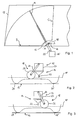
- Fig. 1 is partially a disc 10 of a motor vehicle and a windshield wiper device for wiping the disc 10 after a first preferred embodiment of the invention shown.
- the windscreen wiper device comprises two identically formed, synchronous moving wiper arms with wiper blades held thereon, of which in Fig. 1, only the wiper arm 12 with a wiper blade held thereon 14, and a drive shown only very schematically in FIG 15, by means of which the wiper arms between respective Wischarmendlagen and accordingly the wiper blades between corresponding end positions swinging back and forth.
- Fig. 1 only the first end position B and the second end position C of the wiper blade 14.
- the windscreen wiper device further includes a guide 16 for one on the wiper arm 12 held runner 18.
- the drive 15 drives the wiper arms via drive shafts, of which in Fig. 1, only the drive shaft 20 is shown.
- the wiper arms are in a conventional manner to the drive shafts in a corresponding plane through the respective longitudinal axis of the drive shaft 16 pivotally mounted and are not by in Fig. 1 shown elastic elements in the direction of the disc 10 is pressed.
- the wiper blades are in a conventional manner to the wiper arms held pivotally, but the pivoting range so limited is that when lifting the wiper arms while wiping not with their ends can tilt on the disc.
- the wiper blades are conventionally constructed and one each Wiper lip, in Figs. 2 and 3, the wiper lip 22, which are the wiper arms compared to conventional wiper arms in two ways changed. Since the wiper arms have the same structure, it is sufficient to know the differences only to be explained by the example of the wiper arm 12.
- the rotor 18 is held on the wiper arm 12, which is around a parallel to a longitudinal axis of the wiper arm 12 and thus of the wiper blade 14 extending axis is pivotable.
- the rotor has a pivotally held on the wiper arm 12, U-shaped holder 24, between the free ends of a rotor wheel 26th is rotatably mounted.
- the impeller 26 moves in the groove-like Leadership 16.
- the guide 16 is formed as a circular segment-shaped groove in the Longitudinal section shown in more detail in Figs. 2 and 3 is shown. Each at the ends the guide 16 are depressions 28, 28 'are provided, in which the Rotor wheel 26 briefly engages when the wiper arm 12, the corresponding Wischerarmendlagen or the wiper blade 14, the corresponding End positions B and C has reached.
- the asymmetrical, U-shaped profile 27 of the wiper arm 12 in the area of the rotor 18, the length of the free legs of the U-shaped holder 20, the diameter of the rotor wheel 16 and the distance of the wiper arm 12 of the guide 16 are chosen so that upon movement of the Wiper blade 14 from the end position B in the end position C or a corresponding Movement of the wiper arm 14, the impeller 26 only from the Dead weight of the rotor 18 is pressed onto the guide 16, so that the wiper blade 14 with the normal contact pressure with its wiper lip 22 rests on the disc 10.
- the wiper blade is rotated to the wiper lip of to lift the disc. Since the windscreen wiper device differs from the Windscreen wiper device of the first embodiment only in the Training the wiper arm differs, be different for the other parts the same reference numerals are used and the same explanations apply.
- the wiper arm 12 ' in contrast to the wiper arm in the Section between the drive shaft 14 and the rotor 18 a hinge 30, by means of which a free end 32 of the wiper arm 12 'opposite the portion 34 connected to the drive shaft 20 is rotatable is.
- the rotor 18 Upon reaching the second end position C and reversal of the movement in the direction the first end position B, the rotor 18 is in the in Fig. 3 shown Läuferendlage folded, now the free end 32 of the wiper arm 12 ' and thus the wiper blade 14 is rotated in Fig. 3 counterclockwise or is pivoted, so that the wiper lip 22, but not the wiper arm 12 'is lifted off the disc.
Landscapes
- Engineering & Computer Science (AREA)
- Mechanical Engineering (AREA)
- Transmission Devices (AREA)
- Window Of Vehicle (AREA)
Priority Applications (3)
| Application Number | Priority Date | Filing Date | Title |
|---|---|---|---|
| DE502004000238T DE502004000238D1 (de) | 2004-04-01 | 2004-04-01 | Verfahren zum Wischen einer Scheibe eines Kraftahrzeugs und Scheibenwischvorrichtung |
| AT04008014T ATE315505T1 (de) | 2004-04-01 | 2004-04-01 | Verfahren zum wischen einer scheibe eines kraftahrzeugs und scheibenwischvorrichtung |
| EP04008014A EP1582425B1 (fr) | 2004-04-01 | 2004-04-01 | Méthode pour essuyer le pare-brise d'un véhicule et dispositif pour celle-ci |
Applications Claiming Priority (1)
| Application Number | Priority Date | Filing Date | Title |
|---|---|---|---|
| EP04008014A EP1582425B1 (fr) | 2004-04-01 | 2004-04-01 | Méthode pour essuyer le pare-brise d'un véhicule et dispositif pour celle-ci |
Publications (2)
| Publication Number | Publication Date |
|---|---|
| EP1582425A1 true EP1582425A1 (fr) | 2005-10-05 |
| EP1582425B1 EP1582425B1 (fr) | 2006-01-11 |
Family
ID=34878242
Family Applications (1)
| Application Number | Title | Priority Date | Filing Date |
|---|---|---|---|
| EP04008014A Expired - Lifetime EP1582425B1 (fr) | 2004-04-01 | 2004-04-01 | Méthode pour essuyer le pare-brise d'un véhicule et dispositif pour celle-ci |
Country Status (3)
| Country | Link |
|---|---|
| EP (1) | EP1582425B1 (fr) |
| AT (1) | ATE315505T1 (fr) |
| DE (1) | DE502004000238D1 (fr) |
Citations (2)
| Publication number | Priority date | Publication date | Assignee | Title |
|---|---|---|---|---|
| DE1246442B (de) * | 1963-02-19 | 1967-08-03 | Marian Trzebinski | Abhebevorrichtung fuer einen Kraftfahrzeugscheibenwischer |
| DE1480726A1 (de) * | 1965-09-15 | 1970-04-23 | Zuse Dipl Ing Dr Konrad | Verfahren und Vorrichtung zum selbsttaetigen Scheibenwischen,insbesondere an Kraftfahrzeugen |
-
2004
- 2004-04-01 DE DE502004000238T patent/DE502004000238D1/de not_active Expired - Lifetime
- 2004-04-01 AT AT04008014T patent/ATE315505T1/de not_active IP Right Cessation
- 2004-04-01 EP EP04008014A patent/EP1582425B1/fr not_active Expired - Lifetime
Patent Citations (2)
| Publication number | Priority date | Publication date | Assignee | Title |
|---|---|---|---|---|
| DE1246442B (de) * | 1963-02-19 | 1967-08-03 | Marian Trzebinski | Abhebevorrichtung fuer einen Kraftfahrzeugscheibenwischer |
| DE1480726A1 (de) * | 1965-09-15 | 1970-04-23 | Zuse Dipl Ing Dr Konrad | Verfahren und Vorrichtung zum selbsttaetigen Scheibenwischen,insbesondere an Kraftfahrzeugen |
Also Published As
| Publication number | Publication date |
|---|---|
| EP1582425B1 (fr) | 2006-01-11 |
| DE502004000238D1 (de) | 2006-04-06 |
| ATE315505T1 (de) | 2006-02-15 |
Similar Documents
| Publication | Publication Date | Title |
|---|---|---|
| DE10159052A1 (de) | Scheibenwischvorrichtung, insbesondere für ein Kraftfahrzeug | |
| DE4028494C2 (de) | Scheibenwischer für Kraftfahrzeuge | |
| EP0708205B1 (fr) | Procédé et dispositif de traitement des surfaces de roulement de rails par rectification tangentielle | |
| EP2002060B1 (fr) | Dispositif de meulage des rails d'une voie | |
| DE202016101927U1 (de) | Bürstenschwenkvorrichtung, Seitenwaschbürste und damit ausgestattete Fahrzeugwaschanlage | |
| EP3256351B1 (fr) | Entraînement d'essuie-glace muni d'un moyen d'arrêt mécanique | |
| EP3096987B1 (fr) | Systeme d'essuie glace et procede d'essuyage | |
| EP2775035B1 (fr) | Balayeuse | |
| EP1582425B1 (fr) | Méthode pour essuyer le pare-brise d'un véhicule et dispositif pour celle-ci | |
| DE202017106396U1 (de) | Ausziehbares Scheibenwischersystem | |
| DE2203269A1 (de) | Scheibenwischanlage fuer trapezfoermige scheiben | |
| DE69301333T2 (de) | Scheibenwischeranlage mit aktivem, längenverstellbarem Wischerarm | |
| DE2413290A1 (de) | Scheibenwischeinrichtung fuer scheinwerfer von kraftfahrzeugen | |
| EP1238874A1 (fr) | Essuie-vitre | |
| DE69102123T2 (de) | Scheibenwischer mit variabler Schwenkbewegung. | |
| DE19949446C2 (de) | Scheibenwischeranordnung für eine Windschutzscheibe | |
| DE102010008211A1 (de) | Antriebseinrichtung für eine Wischanlage eines Kraftfahrzeugs | |
| DE102011108911A1 (de) | Scheibenwischeranlage | |
| EP0911233B1 (fr) | Dispositif de lavage et de polissage de véhicules | |
| DE102004056676B4 (de) | Wischanlage für Fahrzeugscheiben | |
| DE102010055738A1 (de) | Borsten-Schleifvorrichtung zum Abrunden von Borstenenden und Verfahren zum Schleifen von Borstenenden | |
| DE3931520C2 (de) | Insektenreinigungsvorrichtung für Fahrzeugscheiben | |
| DE2547661C2 (fr) | ||
| AT501251B1 (de) | Vorrichtung zur behandlung und strukturierung der lauffläche von schiern oder dgl. | |
| DE3921313C2 (fr) |
Legal Events
| Date | Code | Title | Description |
|---|---|---|---|
| GRAP | Despatch of communication of intention to grant a patent |
Free format text: ORIGINAL CODE: EPIDOSNIGR1 |
|
| GRAS | Grant fee paid |
Free format text: ORIGINAL CODE: EPIDOSNIGR3 |
|
| PUAI | Public reference made under article 153(3) epc to a published international application that has entered the european phase |
Free format text: ORIGINAL CODE: 0009012 |
|
| 17P | Request for examination filed |
Effective date: 20041208 |
|
| AK | Designated contracting states |
Kind code of ref document: A1 Designated state(s): AT BE BG CH CY CZ DE DK EE ES FI FR GB GR HU IE IT LI LU MC NL PL PT RO SE SI SK TR |
|
| AX | Request for extension of the european patent |
Extension state: AL HR LT LV MK |
|
| GRAA | (expected) grant |
Free format text: ORIGINAL CODE: 0009210 |
|
| AK | Designated contracting states |
Kind code of ref document: B1 Designated state(s): AT BE BG CH CY CZ DE DK EE ES FI FR GB GR HU IE IT LI LU MC NL PL PT RO SE SI SK TR |
|
| PG25 | Lapsed in a contracting state [announced via postgrant information from national office to epo] |
Ref country code: RO Free format text: LAPSE BECAUSE OF FAILURE TO SUBMIT A TRANSLATION OF THE DESCRIPTION OR TO PAY THE FEE WITHIN THE PRESCRIBED TIME-LIMIT Effective date: 20060111 Ref country code: SI Free format text: LAPSE BECAUSE OF FAILURE TO SUBMIT A TRANSLATION OF THE DESCRIPTION OR TO PAY THE FEE WITHIN THE PRESCRIBED TIME-LIMIT Effective date: 20060111 Ref country code: FI Free format text: LAPSE BECAUSE OF FAILURE TO SUBMIT A TRANSLATION OF THE DESCRIPTION OR TO PAY THE FEE WITHIN THE PRESCRIBED TIME-LIMIT Effective date: 20060111 Ref country code: GB Free format text: LAPSE BECAUSE OF FAILURE TO SUBMIT A TRANSLATION OF THE DESCRIPTION OR TO PAY THE FEE WITHIN THE PRESCRIBED TIME-LIMIT Effective date: 20060111 Ref country code: PL Free format text: LAPSE BECAUSE OF FAILURE TO SUBMIT A TRANSLATION OF THE DESCRIPTION OR TO PAY THE FEE WITHIN THE PRESCRIBED TIME-LIMIT Effective date: 20060111 Ref country code: SK Free format text: LAPSE BECAUSE OF FAILURE TO SUBMIT A TRANSLATION OF THE DESCRIPTION OR TO PAY THE FEE WITHIN THE PRESCRIBED TIME-LIMIT Effective date: 20060111 Ref country code: IE Free format text: LAPSE BECAUSE OF FAILURE TO SUBMIT A TRANSLATION OF THE DESCRIPTION OR TO PAY THE FEE WITHIN THE PRESCRIBED TIME-LIMIT Effective date: 20060111 Ref country code: NL Free format text: LAPSE BECAUSE OF FAILURE TO SUBMIT A TRANSLATION OF THE DESCRIPTION OR TO PAY THE FEE WITHIN THE PRESCRIBED TIME-LIMIT Effective date: 20060111 |
|
| REG | Reference to a national code |
Ref country code: CH Ref legal event code: EP |
|
| REG | Reference to a national code |
Ref country code: IE Ref legal event code: FG4D Free format text: LANGUAGE OF EP DOCUMENT: GERMAN |
|
| PG25 | Lapsed in a contracting state [announced via postgrant information from national office to epo] |
Ref country code: AT Free format text: LAPSE BECAUSE OF NON-PAYMENT OF DUE FEES Effective date: 20060401 |
|
| REF | Corresponds to: |
Ref document number: 502004000238 Country of ref document: DE Date of ref document: 20060406 Kind code of ref document: P |
|
| PG25 | Lapsed in a contracting state [announced via postgrant information from national office to epo] |
Ref country code: SE Free format text: LAPSE BECAUSE OF FAILURE TO SUBMIT A TRANSLATION OF THE DESCRIPTION OR TO PAY THE FEE WITHIN THE PRESCRIBED TIME-LIMIT Effective date: 20060411 Ref country code: BG Free format text: LAPSE BECAUSE OF FAILURE TO SUBMIT A TRANSLATION OF THE DESCRIPTION OR TO PAY THE FEE WITHIN THE PRESCRIBED TIME-LIMIT Effective date: 20060411 Ref country code: DK Free format text: LAPSE BECAUSE OF FAILURE TO SUBMIT A TRANSLATION OF THE DESCRIPTION OR TO PAY THE FEE WITHIN THE PRESCRIBED TIME-LIMIT Effective date: 20060411 |
|
| PG25 | Lapsed in a contracting state [announced via postgrant information from national office to epo] |
Ref country code: ES Free format text: LAPSE BECAUSE OF FAILURE TO SUBMIT A TRANSLATION OF THE DESCRIPTION OR TO PAY THE FEE WITHIN THE PRESCRIBED TIME-LIMIT Effective date: 20060422 |
|
| PG25 | Lapsed in a contracting state [announced via postgrant information from national office to epo] |
Ref country code: MC Free format text: LAPSE BECAUSE OF NON-PAYMENT OF DUE FEES Effective date: 20060430 Ref country code: BE Free format text: LAPSE BECAUSE OF NON-PAYMENT OF DUE FEES Effective date: 20060430 |
|
| PG25 | Lapsed in a contracting state [announced via postgrant information from national office to epo] |
Ref country code: PT Free format text: LAPSE BECAUSE OF FAILURE TO SUBMIT A TRANSLATION OF THE DESCRIPTION OR TO PAY THE FEE WITHIN THE PRESCRIBED TIME-LIMIT Effective date: 20060612 |
|
| AKX | Designation fees paid |
Designated state(s): AT BE BG CH CY CZ DE DK EE ES FI FR GB GR HU IE IT LI LU MC NL PL PT RO SE SI SK TR |
|
| NLV1 | Nl: lapsed or annulled due to failure to fulfill the requirements of art. 29p and 29m of the patents act | ||
| GBV | Gb: ep patent (uk) treated as always having been void in accordance with gb section 77(7)/1977 [no translation filed] |
Effective date: 20060111 |
|
| ET | Fr: translation filed | ||
| REG | Reference to a national code |
Ref country code: IE Ref legal event code: FD4D |
|
| PLBE | No opposition filed within time limit |
Free format text: ORIGINAL CODE: 0009261 |
|
| STAA | Information on the status of an ep patent application or granted ep patent |
Free format text: STATUS: NO OPPOSITION FILED WITHIN TIME LIMIT |
|
| 26N | No opposition filed |
Effective date: 20061012 |
|
| BERE | Be: lapsed |
Owner name: DELPHI TECHNOLOGIES, INC. Effective date: 20060430 |
|
| PG25 | Lapsed in a contracting state [announced via postgrant information from national office to epo] |
Ref country code: CZ Free format text: LAPSE BECAUSE OF FAILURE TO SUBMIT A TRANSLATION OF THE DESCRIPTION OR TO PAY THE FEE WITHIN THE PRESCRIBED TIME-LIMIT Effective date: 20060111 Ref country code: GR Free format text: LAPSE BECAUSE OF FAILURE TO SUBMIT A TRANSLATION OF THE DESCRIPTION OR TO PAY THE FEE WITHIN THE PRESCRIBED TIME-LIMIT Effective date: 20060412 |
|
| PG25 | Lapsed in a contracting state [announced via postgrant information from national office to epo] |
Ref country code: EE Free format text: LAPSE BECAUSE OF FAILURE TO SUBMIT A TRANSLATION OF THE DESCRIPTION OR TO PAY THE FEE WITHIN THE PRESCRIBED TIME-LIMIT Effective date: 20060111 |
|
| PG25 | Lapsed in a contracting state [announced via postgrant information from national office to epo] |
Ref country code: TR Free format text: LAPSE BECAUSE OF FAILURE TO SUBMIT A TRANSLATION OF THE DESCRIPTION OR TO PAY THE FEE WITHIN THE PRESCRIBED TIME-LIMIT Effective date: 20060111 Ref country code: LU Free format text: LAPSE BECAUSE OF NON-PAYMENT OF DUE FEES Effective date: 20060401 Ref country code: HU Free format text: LAPSE BECAUSE OF FAILURE TO SUBMIT A TRANSLATION OF THE DESCRIPTION OR TO PAY THE FEE WITHIN THE PRESCRIBED TIME-LIMIT Effective date: 20060712 |
|
| PG25 | Lapsed in a contracting state [announced via postgrant information from national office to epo] |
Ref country code: CY Free format text: LAPSE BECAUSE OF FAILURE TO SUBMIT A TRANSLATION OF THE DESCRIPTION OR TO PAY THE FEE WITHIN THE PRESCRIBED TIME-LIMIT Effective date: 20060111 |
|
| REG | Reference to a national code |
Ref country code: CH Ref legal event code: PL |
|
| PG25 | Lapsed in a contracting state [announced via postgrant information from national office to epo] |
Ref country code: LI Free format text: LAPSE BECAUSE OF NON-PAYMENT OF DUE FEES Effective date: 20080430 Ref country code: CH Free format text: LAPSE BECAUSE OF NON-PAYMENT OF DUE FEES Effective date: 20080430 |
|
| REG | Reference to a national code |
Ref country code: FR Ref legal event code: PLFP Year of fee payment: 13 |
|
| REG | Reference to a national code |
Ref country code: FR Ref legal event code: PLFP Year of fee payment: 14 |
|
| REG | Reference to a national code |
Ref country code: FR Ref legal event code: PLFP Year of fee payment: 15 |
|
| REG | Reference to a national code |
Ref country code: DE Ref legal event code: R082 Ref document number: 502004000238 Country of ref document: DE Representative=s name: MANITZ FINSTERWALD PATENT- UND RECHTSANWALTSPA, DE Ref country code: DE Ref legal event code: R082 Ref document number: 502004000238 Country of ref document: DE Representative=s name: MANITZ FINSTERWALD PATENTANWAELTE PARTMBB, DE Ref country code: DE Ref legal event code: R081 Ref document number: 502004000238 Country of ref document: DE Owner name: APTIV TECHNOLOGIES LIMITED, BB Free format text: FORMER OWNER: DELPHI TECHNOLOGIES, INC., TROY, MICH., US |
|
| PGFP | Annual fee paid to national office [announced via postgrant information from national office to epo] |
Ref country code: IT Payment date: 20190423 Year of fee payment: 16 |
|
| PGFP | Annual fee paid to national office [announced via postgrant information from national office to epo] |
Ref country code: FR Payment date: 20190425 Year of fee payment: 16 |
|
| PG25 | Lapsed in a contracting state [announced via postgrant information from national office to epo] |
Ref country code: FR Free format text: LAPSE BECAUSE OF NON-PAYMENT OF DUE FEES Effective date: 20200430 |
|
| PG25 | Lapsed in a contracting state [announced via postgrant information from national office to epo] |
Ref country code: IT Free format text: LAPSE BECAUSE OF NON-PAYMENT OF DUE FEES Effective date: 20200401 |
|
| P01 | Opt-out of the competence of the unified patent court (upc) registered |
Effective date: 20230425 |
|
| PGFP | Annual fee paid to national office [announced via postgrant information from national office to epo] |
Ref country code: DE Payment date: 20230426 Year of fee payment: 20 |
|
| REG | Reference to a national code |
Ref country code: DE Ref legal event code: R071 Ref document number: 502004000238 Country of ref document: DE |