EP1580974B1 - Internet-Fernsprechanrufsystem und entsprechendes Verfahren - Google Patents
Internet-Fernsprechanrufsystem und entsprechendes Verfahren Download PDFInfo
- Publication number
- EP1580974B1 EP1580974B1 EP05006165A EP05006165A EP1580974B1 EP 1580974 B1 EP1580974 B1 EP 1580974B1 EP 05006165 A EP05006165 A EP 05006165A EP 05006165 A EP05006165 A EP 05006165A EP 1580974 B1 EP1580974 B1 EP 1580974B1
- Authority
- EP
- European Patent Office
- Prior art keywords
- telephone
- uris
- uri
- server apparatus
- internet
- Prior art date
- Legal status (The legal status is an assumption and is not a legal conclusion. Google has not performed a legal analysis and makes no representation as to the accuracy of the status listed.)
- Expired - Fee Related
Links
- 238000000034 method Methods 0.000 title claims description 183
- 230000006854 communication Effects 0.000 claims description 45
- 238000004891 communication Methods 0.000 claims description 35
- 230000004044 response Effects 0.000 claims description 11
- 230000000977 initiatory effect Effects 0.000 claims description 7
- 238000013507 mapping Methods 0.000 claims description 3
- 230000006870 function Effects 0.000 description 19
- 238000010586 diagram Methods 0.000 description 8
- 230000005540 biological transmission Effects 0.000 description 2
- 238000006243 chemical reaction Methods 0.000 description 2
- 230000000694 effects Effects 0.000 description 2
- 238000004458 analytical method Methods 0.000 description 1
- 238000005516 engineering process Methods 0.000 description 1
- 239000004973 liquid crystal related substance Substances 0.000 description 1
- 239000000463 material Substances 0.000 description 1
- 238000012986 modification Methods 0.000 description 1
- 230000004048 modification Effects 0.000 description 1
- 238000013519 translation Methods 0.000 description 1
Images


Classifications
-
- H—ELECTRICITY
- H04—ELECTRIC COMMUNICATION TECHNIQUE
- H04M—TELEPHONIC COMMUNICATION
- H04M7/00—Arrangements for interconnection between switching centres
- H04M7/006—Networks other than PSTN/ISDN providing telephone service, e.g. Voice over Internet Protocol (VoIP), including next generation networks with a packet-switched transport layer
- H04M7/0066—Details of access arrangements to the networks
- H04M7/0069—Details of access arrangements to the networks comprising a residential gateway, e.g. those which provide an adapter for POTS or ISDN terminals
-
- H—ELECTRICITY
- H04—ELECTRIC COMMUNICATION TECHNIQUE
- H04M—TELEPHONIC COMMUNICATION
- H04M3/00—Automatic or semi-automatic exchanges
- H04M3/42—Systems providing special services or facilities to subscribers
- H04M3/42314—Systems providing special services or facilities to subscribers in private branch exchanges
-
- H—ELECTRICITY
- H04—ELECTRIC COMMUNICATION TECHNIQUE
- H04M—TELEPHONIC COMMUNICATION
- H04M3/00—Automatic or semi-automatic exchanges
- H04M3/42—Systems providing special services or facilities to subscribers
- H04M3/46—Arrangements for calling a number of substations in a predetermined sequence until an answer is obtained
- H04M3/465—Arrangements for simultaneously calling a number of substations until an answer is obtained
-
- H—ELECTRICITY
- H04—ELECTRIC COMMUNICATION TECHNIQUE
- H04M—TELEPHONIC COMMUNICATION
- H04M3/00—Automatic or semi-automatic exchanges
- H04M3/42—Systems providing special services or facilities to subscribers
- H04M3/487—Arrangements for providing information services, e.g. recorded voice services or time announcements
- H04M3/493—Interactive information services, e.g. directory enquiries ; Arrangements therefor, e.g. interactive voice response [IVR] systems or voice portals
- H04M3/4931—Directory assistance systems
-
- H—ELECTRICITY
- H04—ELECTRIC COMMUNICATION TECHNIQUE
- H04M—TELEPHONIC COMMUNICATION
- H04M7/00—Arrangements for interconnection between switching centres
- H04M7/006—Networks other than PSTN/ISDN providing telephone service, e.g. Voice over Internet Protocol (VoIP), including next generation networks with a packet-switched transport layer
-
- H—ELECTRICITY
- H04—ELECTRIC COMMUNICATION TECHNIQUE
- H04M—TELEPHONIC COMMUNICATION
- H04M1/00—Substation equipment, e.g. for use by subscribers
- H04M1/253—Telephone sets using digital voice transmission
- H04M1/2535—Telephone sets using digital voice transmission adapted for voice communication over an Internet Protocol [IP] network
-
- H—ELECTRICITY
- H04—ELECTRIC COMMUNICATION TECHNIQUE
- H04M—TELEPHONIC COMMUNICATION
- H04M2203/00—Aspects of automatic or semi-automatic exchanges
- H04M2203/20—Aspects of automatic or semi-automatic exchanges related to features of supplementary services
- H04M2203/2044—Group features, e.g. closed user group
-
- Y—GENERAL TAGGING OF NEW TECHNOLOGICAL DEVELOPMENTS; GENERAL TAGGING OF CROSS-SECTIONAL TECHNOLOGIES SPANNING OVER SEVERAL SECTIONS OF THE IPC; TECHNICAL SUBJECTS COVERED BY FORMER USPC CROSS-REFERENCE ART COLLECTIONS [XRACs] AND DIGESTS
- Y10—TECHNICAL SUBJECTS COVERED BY FORMER USPC
- Y10S—TECHNICAL SUBJECTS COVERED BY FORMER USPC CROSS-REFERENCE ART COLLECTIONS [XRACs] AND DIGESTS
- Y10S379/00—Telephonic communications
- Y10S379/90—Internet, e.g. Internet phone, webphone, internet-based telephony
Definitions
- the present invention relates to an Internet telephone, a server apparatus, and an Internet telephone system that perform a telephone call via the Internet, and relates to a calling method via an Internet network.
- a conventional network that is used by so-called Internet telephone has been configured as follows.
- a calling management server (known as gatekeeper) is provided within an Internet telephone network.
- This gatekeeper has functions to receive a destination phone number from each telephone, to convert the phone number into a corresponding IP address, and to return the telephone number back to the originating telephone.
- the telephone number When an operator inputs the desired telephone number, the telephone number is called to the gate keeper.
- the telephone receives, from the gatekeeper, an IP address that corresponds to the telephone number, an originating telephone can access, based on the IP address, a destination telephone via the gatekeeper, or directly access the destination telephone without involving the gatekeeper. Accordingly, a telephone call becomes available via the Internet (see Related Art 1).
- a router is normally involved between the gatekeeper and each telephone.
- a plurality of Internet telephones, configuring a group in a network, are connected to such a router.
- Telephones within the same group have IP addresses having a common network address.
- telephones within the same department are configured as the same group in the network.
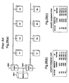
- Fig. 28 (a) illustrates a network configuration of a general Internet telephone system.
- router A 2802 and router B 2803 are connected to call management server (server) 2801.
- Internet telephones A1 - A4, configuring group (A) are connected to router A 2802, while Internet telephones B1 - B4, configuring group (B) are connected to router B 2803.
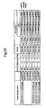
- Fig. 28 (b) and (c) illustrate management charts that register telephone numbers assigned to each Internet telephone and the corresponding IP addresses.
- Fig. 28 (b) and (c) respectively illustrate management charts of group (A) and group (B).
- telephone numbers are extension numbers used in a corporate office setting.
- telephone numbers 1001 - 1004 are respectively assigned to Internet telephones (terminals) A1 - A4, and have IP addresses of (192. 168. 1. 1) - (192. 168. 1. 4).
- Network address (192. 168. 1) is commonly used for the above IP addresses of group (A) terminals.
- telephone numbers 2001 - 2004 are respectively assigned to Internet telephones (terminals) B1 - B4, and have IP addresses of (192. 168. 2. 1) - (192. 168. 2. 4).
- Network address (192. 168. 2) is commonly used for the above IP addresses of group (B) terminals.
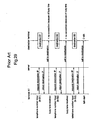
- Fig. 29 is a sequence diagram illustrating an operation of a conventional Internet telephone system.
- terminal A1 when terminal A1 places a call to terminal B1, the caller first inputs telephone number (2001) of terminal B1. Upon obtaining the telephone number, terminal A1 transmits, to server 2801, a request for the IP address of terminal B1. Then, server 2801 provides the IP address of terminal B1. Based on the obtained IP address, terminal A1 places a call to terminal B1.
- terminal B1 is busy, thus the connection to terminal B1 is unsuccessful, and terminal A1 receives a busy tone.
- the caller hangs up the telephone, and inputs telephone number (2002) of terminal B2.
- terminal B2 is called when terminal A1 obtains the IP address of terminal B2 from server 2801.
- terminal B2 is also busy, thus the connection to terminal B2 is unsuccessful, and terminal A1 receives a busy tone.
- the caller hangs up the telephone, and inputs telephone number (2003) of an adjacent terminal B3.
- terminal B3 is called when terminal A1 obtains the IP address of terminal B3 from server 2801.
- terminal B3 is not busy, thus the connection between terminal A1 and terminal B3 is successful. Then, a message to the operator of terminal B1 is delivered to the operator of terminal B3. As described above, when one terminal in a department is busy, the operator needs to dial a different number of an adjacent terminal.
- US 6,442,268 B1 relates to a method of implementing a line group function in a communications network based on ITU-T standard H.323.
- the document describes that the line group function is provided by implementing a Proxy function as a central call control.
- a Proxy server knows the transport addresses of all members of a line group for which the Proxy server can be contacted via a group address. When a call for this group address is received by the Proxy server, same attempts to set-up a connection to one of the line group members. If no response message has been transmitted to the Proxy server from the one group end point within a predetermined time, the Proxy function transmits a connection set-up message to another one of the group end points. This procedure, also referred to as hunting group line function, is repeated until one of the group end points transmits a response message.
- the present invention is provided to address the above-described problems.
- the purpose of the invention is to provide an Internet telephone, a network server, a calling method, and an Internet telephone system that automatically redial a different number within the same network group, in a case where a destination telephone line is unavailable.
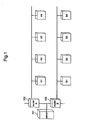
- Fig. 1 illustrates a configuration of a network that connects Internet telephones according to the first embodiment of the present invention.
- router A 102 and router B 103 are connected to a call management server (hereafter referred to as "server") 101.
- server 101 Internet telephones A1 - A4 configuring group (A) are connected to router A 102, while Internet telephones B1 - B4 configuring group (B) are connected to router B103.
- Each group within the network of Fig. 1 can be considered as a department of a corporation.
- the setting of the Internet telephones in a department is illustrated in Fig. 1 .
- FIG. 1 illustrates a situation where Internet telephones are connected to a router
- the configuration can be made such that each ordinary telephone (without the Internet telephone functions) is connected to a control apparatus that facilitates the Internet telephone functions (hereafter referred to as "control adaptor").
- control adaptor a control apparatus that facilitates the Internet telephone functions
- ordinary telephones are connected to such a control adaptor in order to function as Internet telephones.
- Fig. 2 illustrates charts describing the telephone numbers and IP addresses assigned to the Internet telephones connected to the network shown in Fig. 1 .
- Fig. 2 (a) shows the telephone numbers and IP addresses assigned to the Internet telephones configuring group (A).
- Fig. 2 (b) shows the telephone numbers and IP addresses assigned to the Internet telephones configuring group (B).
- Internet telephones (terminals) A1 - A4 respectively have assigned telephone numbers 0310000000 - 0310000003 and IP addresses 192.168.1.1 - 192.168.1.4.
- Internet telephones (terminals) B 1 - B4 respectively have assigned telephone numbers 0310001000 - 0310001003 and IP addresses 192.168.2.1 - 192.168.2.4.
- telephone numbers assigned to terminal A1 and terminal B1 are main numbers of group (A) and group (B) respectively.
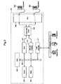
- Fig. 3 is a block diagram illustrating a configuration of the Internet telephone according to the first embodiment of the present invention.
- the Internet telephone is configured to connect ordinary telephone 302 with control adaptor 301.
- Control adaptor 301 according to the present invention can connect two ordinary telephones 302 in order to facilitate each telephone to function as an Internet telephone.
- a configuration can also be made such that more than three telephones can be connected to control adaptor 301.
- Control adaptor 301 is provided with CPU 303 that controls the entire operation of the Internet telephone.
- ROM 305 and RAM 306 are connected to CPU 303 via control bus 304.
- ROM 305 stores a control program for control adaptor 301.
- CPU 303 retrieves and executes the control program.
- RAM 306 functions as a work memory when CPU 303 executes the control program.
- a flash ROM is used as ROM 305, while an SDRAM is used as RAM 306.
- Crosspoint mixer 308 is also connected to CPU 303 via port 307.
- Crosspoint mixer 308 has switching and mixing functions of talk lines for the two telephones connected via an NCU (Network Control Unit), which is later described.
- NCU Network Control Unit
- NCU 309 is connected to crosspoint mixer 308.
- NCU 309 controls telephone lines connected to control adaptor 301 and connects/cuts a line to an opposing side.
- A/D•D/ACODEC 310 and LAN controller 311 are connected to CPU 303 via control bus 304.
- A/D•D/ACODEC 310 performs an analog/digital conversion of voice data, which is input from telephone 302, and compresses the converted data.
- A/D•D/ACODEC 310 also receives the compressed data via LAN controller 311, decompresses the data, and performs the digital/analog conversion.
- LAN controller 311 controls signals exchanged with an Ethernet (R) that configures the network to which control adaptor 301 is connected. LAN controller 311 also assembles and analyses packet data transmitted on the network.
- R Ethernet
- control adaptor 301 When an Internet telephone is used for the above configuration, instead of connecting an ordinary telephone to control adaptor 301, a control board having a function of control adaptor 301 is installed to an Internet telephone.
- Fig. 4 is a block diagram illustrating a general configuration of server 101 according to the first embodiment of the present invention.
- Server 101 according to the first embodiment has a function of a DNS (Domain Name System) server that provides an IP address in response to a request for a host name.
- server 101 has a function of an ENUM (Telephone Number Mapping) server that employs the ENUM technology which specifies a host name with a telephone number.
- DNS Domain Name System
- ENUM Telephone Number Mapping
- server 101 includes CPU 401 that controls the entire operation of server 101.
- Memory 403, network interface (I/F) 404, and input/output apparatus 405 are connected to CPU 401 via control bus 402.
- Memory 403 has a function of a ROM that stores a control program for server 101.
- CPU 401 retrieves and executes the control program.
- Memory 403 also has a function of a RAM that functions as a work memory when CPU 401 executes the control program.
- Memory 403 stores a database necessary to convert the assigned telephone numbers into URIs (Uniform Resource Identifier). Data are described as a resource record called NAPTR (The Naming Authority Pointer) (hereafter referred to as NAPTR resource record). NAPTR resource record describes a single or a plurality of NAPTR resource records. Memory 403 stores IP addresses corresponding to URIs converted from telephone numbers.
- Network I/F 404 controls signals exchanged with the Ethernet, the Ethernet configuring the network to which server 101 is connected.
- Input/output apparatus 405 includes an input device such as a keyboard and a mouse, and an output device such as a liquid crystal display monitor. Input/output apparatus 405 receives an input from an operator, while outputting a status of an operation at server 101.
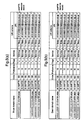
- Fig. 5 illustrates an example of the NAPTR resource record stored in memory 403 of server 101 according to the first embodiment of the present invention.
- Fig. 5 (a) shows the NAPTR resource record corresponding to group (A) shown in Fig. 1
- Fig. 5 (b) shows the NAPTR resource record corresponding to group (B) shown in Fig.1 .
- URIs 81310000000@tokyo.sip.jp
- (81310000003@tokyo.sip.jp) correspond to domain name (0.0.0.0.0.0.0.1.3.1.8.e164.arpa) obtained from the main telephone number of terminal A1 (0310000000).
- URIs (81310000001@tokyo.sip.jp), (81310000002@tokyo.sip.jp) and (81310000003@tokyo.sip.jp) are respectively corresponded to domain name (1.0.0.0.0.0.0. 1.3.1.8.el64.arpa), (2.0.0.0.0.0.0.1.3.1.8. e 164. arpa) and (3.0.0.0.0.0.0.1.3.1.8. e 164. arpa) obtained respectively from the telephone numbers of terminal A2 (0310000001), terminal A3 (0310000002) and terminal A4 (0310000003).
- the domain name obtained from the telephone number of terminal A1 has the corresponding URI of terminal A1, as well as the corresponding URIs of terminal A2, A3 and A4.
- URIs 81310001000@tokyo.sip.jp
- (81310001003@tokyo.sip.jp) correspond to domain name (0.0.0.1.0.0.0.1.3.1.8.e164.arpa) obtained from the main telephone number of terminal B1 (0310010000).
- URIs (81310001001@tokyo.sip.jp), (81310001002@tokyo.sip.jp) and (81310001003@tokyo.sip.jp) are respectively corresponded to domain name (1.0.0.1.0.0.0.1.3.1.8.e164.arpa), (2.0.0.1.0.0.0.1.3.1.8.e164.arpa) and (3.0.0.1.0.0.0.1.3.1.8.e164.arpa) obtained respectively from the telephone numbers of terminal B2 (0310001001), terminal B3 (0310001002) and terminal B4 (0310001003).
- the domain name obtained from the telephone number of terminal B 1 has the corresponding URI of terminal B1, as well as the corresponding URIs of terminal B2, B3 and B4.
- Fig. 6 illustrates charts describing examples of URIs and their corresponding IP addresses stored in memory 403 of server 101 according to the first embodiment of the present invention.
- Fig. 6 (a) shows the URIs and IP addresses that correspond to group (A) shown in Fig. 1 .
- Fig. 6 (b) shows the URIs and IP addresses that correspond to group (B) shown in Fig. 1 .
- URIs 81310000000@tokyo.sip.jp
- (81310000002@tokyo.sip.jp) and (81310000003@tokyo.sip.jp) respectively correspond to IP addresses (192.168.1.1), (192.168.1.2), (192.168.1.3) and (192.168.1.4).
- URIs (81310001000@tokyo.sip.jp), (81310001001@tokyo.sip.jp), (81310001002@tokyo.sip.jp) and (81310001003@tokyo.sip.jp) respectively correspond to IP addresses (192.168.2.1), (192.168.2.2), (192.168.2.3) and (192.168.2.4).
- a calling process between the Internet telephones connected to sever 101 that comprises the above-described embodiment is described with reference to Fig. 7 .
- a calling process from terminal B1 to a terminal within group (A) is described.
- the contrast charts shown in Fig. 6 and the NAPTR resource record shown in Fig. 5 are stored in Memory 403 of server 101.
- terminal B1 When placing a call to a terminal within group (A), terminal B1 obtains one of the input telephone numbers of terminals A1 - A4 from the operator of terminal B1 (ST 701). For example, when placing a call to terminal A1, "0310000000” or “10000000” with "03"("03” means the area code for Tokyo) omitted is input by the operator.
- terminal B 1 Upon obtaining the input telephone number, terminal B 1 transmits, to server 101, a request for URI(s) that correspond(s) to the telephone number (ST 702).
- terminal B1 converts the operator's input number "0310000000” into "+81-3-1-10000000” including the country code according to standard E. 164. Then, "+81310000000” is obtained, with + at the beginning, followed by the numbers. Then, non numerical symbols are deleted, and dots are inserted between the numbers, resulting in "8.1.3.1.0.0.0.0.0.0.0". Finally, the numbers are reversed, and a data string e164.arpa is added at the end, obtaining domain name "0.0.0.0.0.0.0.1.3.1.8. e 164. arpa". Terminal B1 then transmits, to server 101, a request for URI(s) that correspond(s) to the data string.
- server 101 Upon receiving the URI request, server 101 returns corresponding URI (s) according to the NAPTR resource record stored in memory 403, and terminal B1 receives the URI(s) (ST 703).
- URI Identities assigned to the above-noted data string, "81310000000@tokyo.sip.jp", "81310000001@tokyo.sip.jp", "81310000002@tokyo.sip.jp" and "81310000003@tokyo.sip.jp" are returned.
- terminal B1 Upon receiving URI(s), terminal B1 determines whether there are a plurality of URIs (ST 704) in order to determine whether to perform a normal calling process or a group calling process, which is later described.
- the normal calling process starts at ST 705.
- the group calling process starts at ST 706.
- a call is placed to a single destination, while in the group calling process, calls are placed to a plurality of destinations.
- the group calling process is performed since there are four URIs. A detailed description of the normal calling process and the group calling process is provided later.
- terminal B1 determines whether the result of a call (hereafter referred to as "calling result") is "OK to talk". There are at least three kinds of calling result: "OK to talk”, “not OK to talk” and "waiting". One of the results is stored in a predetermined area on RAM 306.
- a communication process starts at ST 708.
- the calling result is other than "OK to talk”
- a disconnection process starts at ST 709.
- the calling process performed by terminal B1 is completed when the communication between the operator of terminal B1 and the operator of the destination is finished.
- the disconnection process the calling process is terminated after proceeding to the disconnection process.
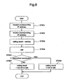
- Fig. 8 is a flow chart describing the normal calling process according to the first embodiment of the present invention.
- terminal B1 transmits, to server 101, a request for an IP address that corresponds to the received URI (ST 801). For example, when URI "81310000001@tokyo.sip.jp" is received, terminal B1 transmits, to server 101, a request for the IP address that corresponds to the URI.
- server 101 Upon receiving the IP request, server 101 returns a corresponding IP address according to the contract chart stored in memory 403, and terminal B1 receives the IP address (ST 802). In the above-noted example, server 101 returns IP address "192.168.1.2" according to the contract chart shown in Fig. 6 (a) .
- terminal B1 Upon receiving the IP address, terminal B1 initializes the calling result (ST 803). More specifically, terminal B1 initializes the calling result by setting it to "waiting".
- terminal B1 places a call to the received IP address (ST 804).
- a call is placed to "192.168.1.2", performing the calling process to terminal A2.
- terminal B1 determines whether terminal B1 has been successfully connected to the destination (ST 805). When the connection has been successful, terminal B1 switches the calling result to "OK to talk" (ST 806) and terminates the normal calling process. On the other hand, when terminal B1 has not been successfully connected to the destination, terminal B1 switched the calling result to "not OK to talk" (ST 807) and terminates the normal calling process. Accordingly, in the normal calling process, a call is placed to a single destination, and the calling result changes according to whether terminal B1 has been successfully connected to the destination.
- the reason includes cases where the line is busy, or the operator of the destination is not available and there is no response over a predetermined time (in case of no response). In case of no response, and when the destination outputs a signal representing a ring back tone continuously for the predetermined time as counted by the timer, it is usually determined that no connection is possible.
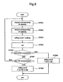
- Fig. 9 is a flow chart describing the group calling process according to the first embodiment of the present invention.
- terminal B1 transmits, to server 101, requests for IP addresses that correspond to the received URIs (ST 901).
- a plurality of URIs are received, thus terminal B1 transmits, to server 101, a request for an IP address that corresponds to one of these URIs.
- terminal B1 transmits, to server 101, a request for an IP address that corresponds to one of these URIs.
- server 101 Upon receiving the IP address request, server 101 returns a corresponding IP address in the same way as described in the normal calling process, and terminal B1 receives the IP address (ST 902).
- terminal B1 Upon receiving the IP address, terminal B1 initializes the calling result (ST 903) and places a call to the IP address (ST 904).
- Terminal B1 determines whether terminal B1 has been successfully connected to the destination (ST 905). When the connection has been successful, terminal B1 switches the calling result to "OK to talk" (ST 906) and terminates the group calling process.
- terminal B1 determines whether there is any URI with an IP address that has not been requested (ST 907). When such a URI exists, terminal B1 returns the process to ST 901 and repeats ST 901 - ST 907 until IP addresses corresponding to all URIs have been requested. When four URIs are received, ST 901 - ST 907 are repeated up to four times.
- terminal B1 switches the calling result to "not OK to talk" (ST 908) and terminates the group calling process. Accordingly, in the group calling process, calls are placed to a plurality of destinations. When terminal B1 has not been successfully connected to any of the destinations, terminal B1 sets the calling result to "not OK to tallc".
- URIs can be randomly selected for their corresponding IP addresses with no particular priority. After IP addresses corresponding to all URIs have been tried, the calling result is switched to "not OK to talk" (ST 908).
- Fig. 10 is a sequence diagram illustrating a situation where terminal B 1 places a call to the main telephone number "0310000000" assigned to terminal A1.
- terminal B1 Upon obtaining input telephone number "0310000000" from the operator of terminal B1, terminal B1 requests URIs that correspond to the telephone number (ST 1001). In response, terminal B1 receives, from server 101, URIs that correspond to the telephone number (ST 1002). In this example, terminal B1 receives four URIs "81310000000@tokyo.sip.jp", "81310000001@tokyo.sip.jp", "81310000002@tokyo.sip.jp" and "81310000003@tokyo.sip.jp".
- terminal B transmits, to server 101, a request for an IP address that corresponds to one of these URIs (ST 1003) and receives an IP address that corresponds to the specified URI (ST 1004).
- terminal B1 requests the IP address that corresponds to URI "81310000000@tokyo.sip.jp" and receives IP address "192.168.1.1 ".
- terminal B1 places a call to the IP address (ST 1005), performing the calling process to terminal A1.
- terminal B1 has not been successfully connected to terminal A1 because of a busy line or other reasons.
- terminal B1 requests an IP address that corresponds to a URI other than the one with the IP address that has been requested (ST 1006) and receives, from server 101, an IP address that corresponds to the specified URI (ST 1007).
- terminal B1 requests the IP address that corresponds to URI "81310000001 @tokyo.sip.jp" and receives IP address "192.168.1.2".
- terminal B1 places a call to the IP address (ST 1008), performing the calling process to terminal A2.
- terminal B1 has not been successfully connected to terminal A2 because of a busy line or other reasons.
- terminal B1 requests an IP address that corresponds to a URI other than those with the IP addresses that have been requested (ST 1009) and receives, from server 101, an IP address that corresponds to the specified URI (ST 1010).
- terminal B1 requests the IP address that corresponds to URI "81310000002@tokyo.sip.jp" and receives IP address "192.168.1.3".
- terminal B1 places a call to the IP address (ST 1011), performing the calling process to terminal A3.
- terminal B1 has no connection problems such as a busy line, and has been successfully connected to terminal A3. Therefore, terminal B1 becomes able to talk with the operator of terminal A3.
- the IP addresses that correspond to the URIs are requested in the order of terminal A1, terminal A2 and terminal A3.
- the destination telephone line is busy or there is continuously no response over a predetermined time
- a different URI is selected, and another call is placed to a destination that corresponds to the different URI. Therefore, the operator does not have to go through the trouble of hanging up the phone and inputting different telephone numbers adjacent to the initial telephone number. This can save significant time and effort during the calling process. The same effect can be expected for the below-described embodiment of the present invention.
- the Internet telephone according to the first embodiment of the present invention when a plurality of URIs are received from server 101, URIs are randomly selected, and their corresponding IP addresses are requested. Then a call is placed to a destination that corresponds to the specified IP address.
- the Internet telephone according to the second embodiment of the present invention sets a priority for selecting URIs, requests a corresponding IP address based on the priority and places a call to a destination that corresponds to the specified IP address.
- the Internet telephone according to the second embodiment of the present invention uses preference field value (hereafter referred to as "preference value”) stored in the NAPTR resource record.
- the preference value is used as a parameter to determine a priority for selecting URIs.
- the preference value serves to determine the order of calls when there are a plurality of NAPTR resource records having the same value in the order field.
- the Internet telephone according to the second embodiment of the present invention uses the preference value as a parameter to determine a priority for selecting URIs so that calls are placed to a plurality of destinations based on the priority.
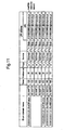
- Fig. 11 is a chart illustrating an example of the NAPTR resource record stored in memory 403 of server 101 according to the second embodiment of the present invention.
- Fig. 11 shows the NAPTR resource record corresponding to group (A) shown in Fig. 1 .
- the NAPTR resource record described in Fig. 11 is the same as described in Fig. 5 (a) expect the preference value; therefore, a detailed description is omitted.
- the NAPTR resource record shown in Fig. 11 is different from the NAPTR resource record shown in Fig. 5 (a) in that different preference values are set in the NAPTR resource record shown in Fig. 11 .
- URIs correspond to domain name "0.0.0.0.0.0.0.1.3.1.8.e164.arpa" obtained from the main telephone number of terminal A1 "0310000000".
- the NAPTR resource record including "81310000000@tokyo.sip.jp” has a preference value of "10”
- the NAPTR resource record including "81310000001 @tokyo.sip.jp” has a preference value of "20”.
- the NAPTR resource record including "81310000002@tokyo.sip.jp” has a preference value of "30”
- the NAPTR resource record including "81310000003@tokyo.sip.jp” has a preference value of "40”.
- Fig. 12 the calling process between the Internet telephones connected to server 101 comprising the above-described embodiment is described with reference to Fig. 12 . Particularly, the calling process from terminal B1 to a terminal within group (A) is described. Information described in Fig. 11 and Fig. 6 is stored in Memory 403 of server 101.
- terminal B1 When placing a call to a terminal within group (A), terminal B1 obtains one of the input telephone numbers of terminals A1 - A4 from the operator (ST 1201). For example, when placing a call to terminal A1, terminal B1 obtains "0310000000” or "10000000” with "03" omitted from the operator.
- terminal B1 Upon obtaining the input telephone number, terminal B1 transmits, to server 101, a request for URI(s) and preference value(s) that correspond to the telephone number (ST 1202).
- terminal B1 obtains a data string "0.0.0.0.0.0.0.1.3.1.8.e164.arpa" from telephone number "0310000000(10000000)”.
- Terminal B1 requests URI(s) and preference value(s) that correspond to the data string.
- server 101 Upon receiving the request for URI(s) and preference value(s), server 101 returns corresponding URI(s) and preference value(s) according to the NAPTR resource record stored in memory 403, and terminal B1 receives the URI(s) and the preference value(s) (ST 1203).
- server 101 returns four URIs and four preference values that correspond to the data string according to the NAPTR resource record shown in Fig. 11 .
- terminal B1 Upon receiving URI(s) and other information, terminal B1 determines whether there are a plurality of URIs (ST 1204). When there are not a plurality of URIs, the normal calling process starts at ST 1205. On the other hand, when there are a plurality of URIs, the group calling process starts at ST 1206.
- the normal calling process according to the second embodiment of the present invention is the same as described in Fig. 8 ; therefore, their description is omitted. The group calling process according to the second embodiment of the present invention is later described.
- terminal B 1 determines whether the calling result is "OK to talk" (ST 1207). When the calling result is "OK to talk”, the communication process starts at ST 1208. When the calling result is other than "OK to talk”, the disconnection process starts at ST 1209. In the communication process, the calling process performed by terminal B1 is completed when the communication between the operator of terminal B1 and the operator of the destination is finished. In the disconnection process, the calling process performed by terminal B1 is terminated after proceeding to the disconnection process.
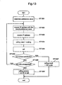
- Fig. 13 is a flow chart describing the group calling process according to the second embodiment of the present invention.
- terminal B1 determines the order of the received preference values (ST 1301). Terminal B1 then transmits, to server 101, a request for an IP address that corresponds to a URI having the lowest preference value (ST 1302).
- terminal B1 Upon receiving the request for an IP address that corresponds to the URI from terminal B1, server 101 returns a corresponding IP address, and terminal B1 receives the IP address (ST 1303). Upon receiving the IP address, terminal B1 initializes the calling result (ST 1304) and places a call to the received IP address (ST 1305). Terminal B1 then determines whether terminal B1 has been successfully connected to the destination (ST 1306). When the connection has been successful, terminal B1 switches the calling result to "OK to talk" (ST 1307) and terminates the group calling process.
- terminal B1 determines whether there is any URI with an IP address that has not been requested (ST 1308). When such a URI exists, terminal B1 returns the process to ST 1302. Terminal B1 then repeats ST 1302 - ST 1308 on a URI having the lowest preference value among such URIs with IP addresses that have not requested. For example, when four URIs are received, ST 1302 - ST 1308 are repeated up to four times.
- terminal B1 switches the calling result to "not OK to talk" (ST 1309) and terminates the group calling process.
- the Internet telephone system when a plurality of URIs are received, when these URIs have different preference values and when terminal B1 has not been successfully connected to a destination corresponding to one of these URIs, a different URI is selected, and another call is placed to a destination corresponding to the different URI. Accordingly, the operator only needs to input one telephone number. Even when no connection can be established with the destination, additional calls are automatically and sequentially placed to different destinations within the same group. Therefore, the operator does not have to go through the trouble of hanging up the phone and inputting different telephone numbers adjacent to the initial telephone number, when no connection can be established with one destination within the same group. This can save significant time and effort during the calling process.
- the Internet telephone according to the second embodiment of the present invention places calls according to the order of the preference values. Accordingly, the order of calls is determined based on the preference values, enabling to specify the order of calls. Particularly, it is possible to place the first call to a destination having the lowest preference value. Therefore, the order of calls can be specified by setting the preference values to accommodate the desired order of calls.
- the preference value stored in the NAPTR resource record is used as a parameter, and calls are placed to a plurality of destinations based on a priority.
- the method for placing calls to a plurality of destinations by using the preference value as a parameter is not limited to a case when calls are placed by setting a priority.
- the same preference value For example, it is also possible to set the same preference value and to place calls simultaneously to all destinations corresponding to URIs having the same preference value.
- the preference values stored in the NAPTR resource record shown in Fig. 5 (a) are all set to "10". Therefore, at ST 1302 shown in Fig. 13 , IP addresses that correspond to all URIs are requested, and calls are placed to all destination terminals (A1 - A4) at ST 1305.
- the Internet telephone according to the second embodiment of the present invention places calls simultaneously to destinations corresponding to all URIs, when the same preference value is set. Therefore, all adjacent telephones can be called simultaneously. This can save time and effort in case of emergency when placing calls without specifying an operator.
- the Internet telephone can be set to receive an instruction to disregard the preference value. Even when different preference values are set, and when the Internet telephone receives an instruction to disregard the preference values, it is possible to disregard the preference values and to place calls simultaneously to destinations corresponding to all URIs. In this case, calls can be placed simultaneously to all adjacent telephones even when different preference values are set. This can save time and effort in case of emergency when placing calls without specifying an operator.
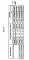
- Fig. 14 illustrates an example of the NAPTR resource record stored in memory 403 of server 101.
- the NAPTR resource record described in Fig. 14 is the same as described in Fig 11 except the preference value; therefore, a detailed description is omitted.
- the NAPTR resource record described in Fig. 14 is different from that of Fig. 11 in that Fig. 14 has groups with the same preference.
- URIs correspond to domain name "0.0.0.0.0.0.0.1.3.1.8.e164.arpa" obtained from the main telephone number of terminal A1 "0310000000".
- the NAPTR resource records including these URIs include "81310000000@tokyo.sip.jp" and "81310000001@tokyo.sip.jp” have a preference value of "10".
- the NAPTR resource records including "81310000002@tokyo.sip.jp" and "81310000003@tokyo.sip.jp” have a preference value of "20". Therefore, for the first time around at ST 1302 shown in Fig.
- the IP addresses corresponding to "81310000000@tokyo.sip.jp" and "81310000001 @tokyo.sip.jp” are requested.
- calls are placed simultaneously to terminal A1 and terminal A2 for the first time around at ST 1305.
- the IP addresses corresponding to "81310000002@tokyo.sip.jp” and "81310000003@tokyo.sip.jp” are requested.
- calls are placed simultaneously to terminal A3 and terminal A4 for the second time around at ST 1305.
- the order of calls can be specified by creating groups which accommodate the desired order of calls.
- Two different calling processes have been described above: a process where different preference values are set, and calls are placed to a plurality of destinations based on the priority set by the preference values; and a process where the same preference value is set, and calls are placed simultaneously to a plurality of destinations.
- configurations can also be made such that where the above two processes operate concurrently. For example, such a configuration is possible by adding a new telephone number to the above-noted telephone numbers (0310000000 - 0310000003). In this example, telephone number "0310000004" is added and is set to make a plurality of calls simultaneously (hereafter referred to as "simultaneous calling number").
- Fig. 15 illustrates an example of the NAPTR resource record stored in memory 403 of server 101.
- the NAPTR resource record described in Fig. 15 is the same as described in Fig. 11 except Fig. 15 has additional NAPTR resource records in the bottom row; therefore a detailed description is omitted.
- URIs "81310000000@tokyo.sip.jp”, "81310000001@tokyo.sip.jp”, "81310000002@tokyo.sip.jp” and "81310000003@tokyo.sip.jp” correspond to domain name "4.0.0.0.0.0.0.1.3.1.8.e164.atpa” obtained from telephone number "0310000004".
- the NAPTR resource records including these URIs have the same preference value "10". Therefore, when telephone number "031000000” is input, calls are placed to a plurality of destinations based on a priority set specified by different preference values. On the other hand, when simultaneous calling telephone number "0310000004" is input, calls are placed simultaneously to a plurality of destinations based on the same preference value.
- the Internet telephone system when a plurality of URIs are received from server 101, when different preference values are set (when the above-noted telephone number 0310000000 is input) and when terminal B1 has not been successfully connected to a URI having the highest priority, another call is placed to a URI with the second highest priority. Accordingly, the operator needs only to input one telephone number. Even when no connection can be established with the destination, additional calls are automatically and sequentially placed to different destinations within the same group. Therefore, even when no connection is possible with one telephone within the same group, the operator does not have to go through the trouble of hanging up the phone and inputting different telephone numbers adjacent to the initial telephone number. This can save significant time and effort during the calling process.
- the Internet telephone system places calls to a plurality of destinations based on a priority specified by the preference values stored in the NAPTR resource record, and uses only sip (Session Initiation Protocol) as a service protocol (communication type).
- sip Session Initiation Protocol
- the Internet telephone according to the third embodiment of the present invention differs in that it combines sip with other service protocols.
- the Internet telephone according to the third embodiment of the present invention uses, for example, e-mail and FAX via telephone as service protocols to be combined with sip.
- service protocols are not limited to these, and the Internet telephone can surely be configured to use H. 323, telephone using H. 323, FAX via the Internet, conventional telephone and the web as service protocols.
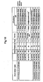
- Fig. 16 illustrates an example of the NAPTR resource record stored in memory 403 of server 101 according to the third embodiment of the present invention.
- the NAPTR resource record described in Fig. 16 is the same as described in Fig. 11 except the bottom two NAPTR resource records of the group of six on top have been added in Fig. 16 ; therefore, a detailed description is omitted.
- URIs correspond to domain name "0.0.0.0.0.0.0.1.3.1.8.e164.arpa" obtained from telephone number "0310000000”.
- the NAPTR resource records including the top four URIs are the same as those in Fig. 11 ; therefore, their description is omitted.
- the upper NAPTR resource record is set to "E2U+message:mailto" in the service field and specifies email as a service protocol (communication type).
- Email address "info@panasonic.co.jp" is specified as a URI.
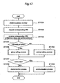
- Fig. 17 the calling process between the Internet telephones connected to server 101 configuring the above-described embodiment is described with reference to Fig. 17 . Particularly, the calling process from terminal B1 to a terminal within group (A) is described. Information described in Fig. 16 and Fig. 6 is stored in memory 403 of server 101.
- terminal B1 When placing a call to a terminal within group (A), terminal B1 obtains one of the input telephone numbers of terminals A1 - A 4 from the operator (ST 1701). For example, when placing a call to terminal A1, terminal B1 obtains "0310000000” or "10000000” with "03"omitted from the operator.
- terminal B1 Upon obtaining the input telephone number, terminal B1 transmits, to server 101, a request for URI(s), preference value(s) and service protocol(s) that correspond to the telephone number (ST 1702).
- terminal B1 obtains a data string "0.0.0.0.0.0.0.1.3.1.8.e164.arpa” from "0310000000(10000000)” and requests URI(s), preference value(s) and service protocol(s) that correspond to the data string.
- server 101 Upon receiving the request for URI(s), preference value(s) and service protocol(s) from tenninal B1, server 101 returns corresponding URI(s), preference value(s) and service protocol(s), and terminal B1 receives the URI(s), the preference value(s) and the service protocol(s) (ST 1703).
- server 101 returns six URIs, six preference values and six service protocols according to the NAPTR resource record shown in Fig. 16 .
- terminal B1 Upon receiving URI (s) and other information, terminal B1 determines whether there are a plurality of URIs (ST 1704). When there are not a plurality of URIs, the normal calling process starts at ST 1705. On the other hand, when there are a plurality of URIs, the group calling process starts at ST 1706.
- the normal calling process according to the third embodiment of the present invention is the same as described in Fig. 8 ; therefore, its description is omitted. The group calling process according to the third embodiment of the present invention is later described.
- terminal B1 determines whether the calling result is "OK to talk" (ST 1707). When the calling result is "OK to talk”, the communication process starts at ST 1708. On the other hand, when the calling result is other than "OK to talk", the disconnection process starts at ST 1709. In the communication process, the calling process performed by terminal B1 is completed when the communication between the operator of terminal B1 and the operator of the destination is finished. In the disconnection process, the calling process performed by terminal B1 is terminated after proceeding to the disconnection process.
- Fig. 18 illustrates a flow chart describing the group calling process according to the third embodiment of the present invention.
- the same ST numbers are used for Fig. 18 , and their detailed description is omitted.
- terminal B1 determines the types of the received service protocols (ST 1801). Terminal B1 then determines whether any service protocol other than sip is included (ST 1802). When no service protocol other than sip is included, ST 1301 - ST 1306 and ST 1308 shown in Fig. 13 are performed. At the same time, terminal B1 switches the calling result to "OK to talk" or "not OK to talk” at ST 1809 and ST 1815, which are later described, and terminates the group calling process.
- terminal B1 first determines the order of the received preference values based on the NAPTR resource records with the sip service protocol (ST 1803). Terminal B1 then transmits, to server 101, a request for an IP address that corresponds to a URI having the lowest preference value (ST 1804).
- server 101 Upon receiving the request for an IP address that corresponds to the URI from terminal B1, server 101 returns a corresponding IP address, and terminal B1 receives the IP address (ST 1805).
- termmal B1 Upon receiving the IP address, termmal B1 initializes the calling result (ST 1806) and places a call to the IP address (ST 1807).
- Terminal B1 determines whether terminal B1 has been successfully connected to the destination (ST 1808). When the connection has been successful, terminal B1 switches the calling result to "OK to talk" (ST 1809) and terminates the group calling process.
- terminal B1 determines whether there is any URI corresponding to sip with an IP address that has not been requested (ST 1810). When such a URI exists, terminal B1 returns the process to ST 1804. Terminal B1 then repeats ST 1804 - ST 1810 on a URI having the lowest preference value among such URIs with IP addresses that have not been requested. For example, when four URIs with the sip protocol are received, ST 1804 - ST 1810 are repeated up to four times.
- terminal B1 After IP addresses that correspond to all URIs with the sip protocol have been requested while repeating ST 1804 - ST 1810, terminal B1 then determines the order of the preference values based on the NAPTR resource records with service protocols other than sip (ST 1811). Terminal B1 then transmits a predetermined template message to a destination that corresponds to a URI having the lowest preference value (ST 1812).
- a template message is sent by email to email address "info@panasonic.co.jp".
- Such a template message can indicate, for instance, "I called Mr. XX, but you seemed to be out of the office. Please return my call.”
- such template messages are not limited to this type and can contain any other information.
- Terminal B1 determines whether the email has been successfully sent (ST 1813). When the email transmission has been successful, terminal B1 switches the calling result to "OK to talk" (ST 1809) and terminates the group calling process. On the other hand, when the email transmission has not been successful, terminal B1 determines whether there is any URI with an IP address that has not been tried (ST 1814). When such a URI exits, terminal B1 returns the process to ST 1812. Terminal B1 then repeats ST 1812 on a URI having the lowest preference value among such URIs with IP addresses that have not been requested. In the example shown in Fig. 16 , a template message is transmitted as a fax message to telephone number "+81310000010". The template message is the same as the one used for email.
- terminal B1 switches the calling result to "not OK to talk" (ST 1815) and terminates the group calling process.
- terminal B1 When terminal B1 has not been successfully connected to destinations corresponding to all URIs that have the sip protocol in the service field, calls are placed to URIs with service protocols other than sip, following processes appropriate for such protocols. Accordingly, even when terminal B1 has not been successfully connected to destinations corresponding to all URIs with sip, it is possible to deliver some message to destinations to which no successful connection has been made by registering processes that use service protocols other than sip.
- the Internet telephone according to the third embodiment of the present invention transmits a predetermined template message to a URI with email or FAX via telephone as a service protocol, when terminal B1 has not been successfully connected to destinations corresponding to all URIs with the sip protocol in the service field. Accordingly, for example, a message can be delivered to ask for returning a call to destinations to which no successful call has been made, by setting a template message to ask for returning a call.
- the Internet telephone according to the second embodiment of the present invention places calls to a plurality of destinations based on the priority specified by the preference values stored in the NAPTR resource record.
- the Internet telephone according to the fourth embodiment of the present invention places calls to a plurality of destinations based on the priority specified by the operator.
- the Internet telephone stores, in memory 403 of server 101, identifications regarding the operators of the destination terminals, and returns URI(s) and identification(s) in response to a URI request from the originating Internet telephone.
- the operator of the originating telephone specifies, by a dial key or the like, the priority for placing calls.
- the Internet telephone places calls according to the instructions from the operator.
- Identifications regarding the operators of the destination terminals can be stored in any form in memory 403 of server 101 according to the fourth embodiment of the present invention. However, it is desirable to store identifications by corresponding them to URIs, since identifications are returned in response to a URI request from the originating Internet telephone.
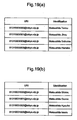
- Fig. 19 illustrates an example of identifications stored in memory 403 of server 101 according to the fourth embodiment of the present invention.
- Fig. 19 (a) shows the URIs and the identifications corresponding to group (A).
- Fig. 19 (b) shows the URIs and the identifications corresponding to group (B).
- Fig. 20 the calling process between the Internet telephones connected to sever 101 that comprises the above-described embodiment is described with reference to Fig. 20 . Particularly, the calling process from terminal B1 to a terminal within group (A) is described. Information described in Fig. 5 , Fig. 6 and Fig. 19 are stored in memory 403 of server 101.
- terminal B1 When placing a call to a terminal within group (A), terminal B1 obtains one of the input telephone numbers of terminals A1 - A4 from the operator (ST 2001). For example, when placing a call to terminal A1, "0310000000” or “10000000” with "03" omitted is obtained from the operator.
- terminal B1 Upon obtaining the input telephone number, terminal B1 transmits, to server 101, a request for URI(s) and identification(s) that correspond to the telephone number (ST 2002). In the above-noted example, terminal B1 obtains a data string "0.0.0.0.0.0.0.1.3.1.8. e164.arpa" from "0310000000(10000000)”. Terminal B1 then requests URI(s) and identification(s) that correspond to the data string.
- server 101 Upon receiving the request for URI(s) and identification(s), server 101 returns corresponding URI(s) according to the NAPTR resource record stored in memory 403, and returns identification(s) that correspond to the URI(s), and terminal B1 receives the URI(s) and the identification(s) (ST 2003).
- server 101 returns four URIs that correspond to the above-noted data string according to the NAPTR resource record shown in Fig. 5 , and returns four identifications that correspond to the URIs according to the contract chart shown in Fig. 19 .
- terminal B1 Upon receiving URI(s) and other information, terminal B1 determines whether there are a plurality of URIs (ST 2004). When there are not a plurality of URIs, the normal calling process starts at ST 2005. On the other hand, when there are a plurality of URIs, the group calling process starts at ST 2006.
- the normal calling process according to the forth embodiment is the same as described in Fig. 8 ; therefore, its description is omitted.
- the group calling process according to the fourth embodiment of the present invention is later described.
- terminal B1 determines whether the calling result is "OK to talk” (ST 2007). When the calling result is "OK to talk”, the communication process starts at ST 2008. On the other hand, when the calling process is other than "OK to talk", the disconnection process starts at ST 2009. In the communication process, the calling process performed by terminal B1 is completed when the communication between the operator of terminal B1 and the operator of the destination is finished. In the disconnection process, the calling process performed by terminal B1 is terminated after proceeding to the disconnection process.
- Fig. 21 illustrates a flow chart describing the group calling process according to the fourth embodiment of the present invention.
- terminal B1 obtains the priority for placing calls, which means the order of calls, from the operator (ST 2101).
- the group calling process starts, all identifications received at ST 2003 shown in Fig. 20 appear on the display of terminal B1.
- the operator of terminal B1 specifies the desired order to call the operators of the destination terminals based on the identifications, and terminal B1 obtains the instructions. For example, the operator of terminal B1 specifies the order of calls descending from the top row to the bottom row of the identifications shown in Fig. 19 (a) .
- terminal B1 Upon obtaining the order of calls, terminal B1 determines the specified order of calls (ST 2102). Terminal B1 then identifies the order of destinations to call in the group calling process. In the above-noted example, it is determined that calls should be placed in the order of "Matsushita Tarou”, “Matsushita Jirou", “Matsushita Saburou” and “Matsushita Hanako”.
- terminal B1 transmits, to server 101, a request for an IP address that corresponds to a URI with an identification that should be called first (ST 2103).
- the IP address that corresponds to "813100000000@tokyo.sip.jp" with identification "Matsushita Tarou” is requested.
- terminal B1 Upon receiving the request for an IP address that corresponds to the URI from terminal B1, server 101 returns a corresponding IP, and terminal B1 receives the IP address (ST 2104). Upon receiving the IP address, terminal B1 initializes the calling result (ST 2105) and places a call to the IP address (ST 2106). Terminal B1 then determines whether terminal B1 has been successfully connected to the destination (ST 2107). When the connection has been successful, terminal B1 switches the calling result to "OK to talk" (ST 2108) and terminates the group calling process.
- terminal B1 determines whether there is any URI with an IP address that has not been requested (ST 2109). When such a URI exits, terminal B1 returns the process to ST 2103. Terminal B1 then repeats ST 2103 - ST 2109 on a URI specified as the highest priority for placing calls among such URIs with IP addresses that have not been requested. For example, when four URIs are received, ST 2103 - ST 2109 are repeated up to four times.
- terminal B1 switches the calling result to "not OK to talk" (ST 2110) and terminates the group calling process.
- calls are placed based on the order of calls specified by the operator. Accordingly, the operator of the originating telephone can specify the operator of the destination to which a message is directed. As a result, it is possible to prevent situations where operators who are not concerned with the message may be interrupted by the call.
- its application may be limited when the Internet telephone is set on a network such as an in-house LAN and cannot be directly accessed from an external network.
- its application is limited when a private IP address is assigned to the Internet telephone on an in-house LAN, and when communication with an external network is made via a router having a function of a NAT (Network Address Translation) (hereafter referred to as NAT router).
- NAT router Network Address Translation
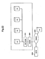
- Fig. 22 illustrates a configuration of a network that connects the Internet telephones according to the fifth embodiment of the present invention.
- Fig. 22 Internet telephones (terminals) A1 - A4 are set on an in-house LAN, and terminal B1 is set on an external network.
- telephone numbers 0310000000 - 0310000003 are respectively assigned to terminals A1 - A4.
- private IP addresses local IP addresses
- 192.168.1.100 -192.168.1.103 are assigned as IP addresses.
- Global IP address 2.2.2.2 is assigned to NAT router 2201.
- Terminal B1 is an Internet telephone set on an external network, configurations are not limited to this.
- Terminal B1 can be a terminal connected via an in-house LAN such as terminals A1 - A4.
- Sever 2204 has the same configuration as described in Fig. 4 except network I/F 404 controls signals with the Internet.
- Memory 403 of server 2204 according to the fifth embodiment of the present invention stores a database (NAPTR resource record) necessary to convert the telephone numbers assigned to terminals A1 - A4 into their corresponding URIs, and stores IP addresses that correspond to the URIs converted from the telephone numbers.
- NAPTR resource record a database necessary to convert the telephone numbers assigned to terminals A1 - A4 into their corresponding URIs
- IP addresses that correspond to the URIs converted from the telephone numbers.
- private IP addresses are assigned to terminals A1 - A4. Therefore, the global IP address of NAT router 2201 corresponds to all of the converted URIs.
- Fig. 23 is a chart illustrating an example of the NAPTR resource record stored in memory 403 of server 2204 according to the fifth embodiment of the present invention.
- Fig. 23 shows the NAPTR resource records corresponding to terminals A1 - A4.
- URIs 81310000000@tokyo.sip.jp:5060
- (81310000001@tokyo.sip.jp:60001) correspond to domain name (0.0.0.0.0.0.0.1.3.1.8.e164.arpa) obtained from the main telephone number of terminal A1 (0310000000).
- URIs (81310000000@tokyo;sip.jp:60001), (81310000000@tokyo.sipjp:60002) and (81310000000@tokyo.sip.jp:60003) respectively correspond to domain names (1.0.0.0.0.0.0.1.3.1.8.e164.arpa), (2.0.0.0.0.0.0.1.3.1.8. e 164. arpa) and (3.0.0.0.0.0.0.1.3.1.8. e 164. arpa) obtained respectively from the telephone numbers of terminal A2 (0310000001), terminal A3 (0310000002) and terminal A4 (0310000003).
- URIs have additional numbers, "5060”, “60001”, “60002” and “60003” respectively. These numbers represent port numbers used for communications.
- the added "5060” is a default port number for sip.
- "60001" - "60003" show examples of port numbers selected from undefined ports. These port numbers are used to perform port forwarding at NAT router 2201.
- NAT router 2201 is configured to correspond specific port numbers to the IP addresses of terminals A1 - A4.
- Fig. 24 illustrates a chart describing specific port numbers and their corresponding private IP addresses stored in NAT router 2201 according to the fifth embodiment of the present invention.
- the private IP address of terminal A1 "192.168.1.100” corresponds to port number "5060”.
- the private IP address of terminal A2 "192.168.1.101” corresponds to port number "60001”.
- the private IP address of terminal A3 "192.168.1.102” corresponds to port number "60002”.
- the private IP address of terminal A4 "192.168.1.103” corresponds to port number "60003”.
- Fig. 25 the calling process from an Internet telephone on an external network to the Internet telephone according to the fifth embodiment of the present invention is described with reference to Fig. 25 .
- the calling process from terminal B1 to one of terminals A1 - A4 is described.
- the NAPTR resource record shown in Fig. 23 is stored in memory 403 of server 2204.
- NAT router 2201 stores information described in Fig. 24 .
- terminal B1 When placing a call to one of terminals A1 - A4, terminal B1 obtains one of the input telephone numbers of terminals A1 - A4 from the operator (ST 2501). For example, when placing a call to terminal A1, terminal B1 obtained the input telephone number of "0310000000” or "10000000” with "03" omitted from the operator.
- terminal B1 Upon obtaining the input telephone number, terminal B1 transmits, to server 2204, a request for URI(s) that correspond(s) to the telephone number (ST 2502).
- a port number is also requested in effect when the URI request is made, since a URI includes a port number.
- terminal B1 obtains a data string "0.0.0.0.0.0.0.1.3.1.8. e164.arpa" from telephone number "031000000(10000000)”.
- Terminal B1 requests URI(s) that correspond(s) to the data string.
- server 2204 Upon receiving the URI request, server 2204 returns corresponding URI(s) according to the NAPTR resource record stored in memory 403, and terminal B1 receives the URI(s) (ST 2503).
- a port number is also received as a result, since a URI includes a port number. Accordingly, terminal B1 determines URI(s) and port number(s) that correspond to the input telephone number.
- server 2204 returns four URIs, which are correspond to the above-noted data string, "81310000000@tokyo.sip.jp:5060", "81310000001@tokyo.sip.jp:60001", "81310000002@tokyo.sip.jp:60002" and "81310000003@tokyo.sip.jp:60003".
- terminal B1 Upon receiving URI(s) and other information, terminal B1 determines whether there are a plurality of URIs (ST 2504). When there are not a plurality of URIs, the normal calling process starts at ST 2505. On the other hand, when there are a plurality of URIs, the group calling process starts at ST 2506. The normal calling process and the group calling process according to the fifth embodiment of the present invention are later described.
- terminal B1 determines whether the calling result is "OK to talk" (ST 2507). When the calling result is "OK to talk”, the communication process starts at ST 2508. On the other hand, when the calling result is other than "OK to tallc", the disconnection process starts at ST 2509. In the communication process, the calling process performed by terminal B1 is completed when the communication between the operator of terminal B1 and the operator of the destination is finished. In the disconnection process, the calling process performed by terminal B1 is terminated after proceeding to the disconnection process.
- Fig. 26 illustrates a flow chart describing the normal calling process according to the fifth embodiment of the present invention.
- terminal B 1 transmits, to server 2204, a request for an IP address that corresponds to the received URI (ST 2601). For example, when URI "81310000000@tokyo.sip.jp:5060" is received, terminal B1 transmits, to server 2204, a request for the IP address that corresponds to the URI.
- server 2204 Upon receiving the IP address request, server 2204 returns the corresponding IP address according to the information stored in memory 403, and terminal B1 receives the IP address (ST 2602). As described above, server 2204 according to the fifth embodiment of the present invention returns IP address (2.2.2.2), since server 2204 only stores the IP address of NAT router 2201. Upon receiving the IP address, terminal B1 corresponds the IP address to the port number received at ST 2503 shown in Fig. 25 . As a result, terminal B1 determines the IP address of NAT router 2201 and the port number of the destination terminal.
- terminal B1 Upon receiving the IP address, terminal B1 initializes the calling result (ST 2603). More specifically, terminal B1 initializes the calling result by setting it to "waiting".
- terminal B1 places a call to the received IP address (ST 2604).
- terminal B1 accesses NAT router 2201 to place a call to the received port number of the destination. More specifically, the IP address of NAT router 2201 and the port number of the destination terminal are specified by describing "sip:2.2.2.2:5060" in the sip invite message.
- terminal B1 determines whether terminal B1 has been successfully connected to the specified destination (ST 2605). When the connection has been successful, terminal B1 switches the calling result to "OK to talk" (ST 2606) and terminates the normal calling process. On the other hand, when the connection has not been successful, terminal B1 switches the calling result to "not OK to talk” (ST 2607) and terminates the normal calling process. Accordingly, in the normal calling process, a call is placed to a single destination, and the calling result changes according to whether terminal B1 has been successfully connected to the destination.
- Fig. 27 illustrates a flow chart describing the group calling process according to the fifth embodiment of the present invention.
- terminal B1 transmits, to server 2204, requests for IP addresses that correspond to the received URIs (ST 2701).
- a plurality of URIs are received. Therefore, terminal B1 transmits, to sever 2204, a request for an IP address that corresponds to one of these URIs.
- terminal B1 when terminal B1 receives URIs "81310000000@tokyo.sip.jp:5060", "81310000001@tokyo.sip.jp:60001", “81310000002@tokyo.sip.jp:60002" and "81310000003@tokyo.sip.jp:60003", terminal B1 transmits, to server 2204, a request for an IP address that corresponds to one of these URIs.
- server 2204 Upon receiving the IP address request, server 2204 returns the IP address of NAT router 2201 in the same way as described in the normal calling process, and terminal B1 receives the IP address (ST 2702). Upon receiving the IP address, in the same way as described in the normal calling process (ST 2503), terminal B1 determines the IP address of NAT router 2201 and the port number of the destination terminal by corresponding the IP address to the port number received at ST 2503 shown in Fig. 25 .
- terminal B1 Upon receiving the IP address, terminal B1 initializes the calling result (ST 2703) and places a call to the IP address (ST 2704). Terminal B1 then determines whether terminal B1 has been successfully connected to the destination (ST 2705). When the connection has been successful, terminal B1 switches the calling result to "OK to talk" (ST 2706) and terminates the group calling process.
- terminal B1 determines whether there is any URI with an IP address that has not been requested (ST 2707). When such a URI exists, terminal B1 returns the process to ST 2701 and repeats ST 2701 - ST 2707 until IP addresses corresponding to all URIs have been requested. When four URIs are received, ST 2701 - ST 2707 are repeated up to four times.
- terminal B1 After IP addresses corresponding to all URIs have been requested while repeating ST 2701 - ST 2707, terminal B1 switches the calling result to "not OK to talk" (ST 2708) and terminates the group calling process. As described above, calls are placed to a plurality of destinations in the group calling process. When terminal B1 has not been successfully connected to any of the destinations, terminal B1 sets the calling result to "not OK to talk".
- the Internet telephone system there is a case where a plurality of URIs are received from server 2204, and where the specified URI includes a port number.
- the specified URI includes a port number.
- a different URI is selected, and another call is placed to a destination specified by a port number included in the specified URI and by an IP address that corresponds to the different URI.
- the operator only needs to input one telephone number. Even when there is no successful connection to that destination, additional calls are automatically and sequentially placed to different destinations within the same group. Therefore, the operator does not have to go through the trouble of hanging up the phone and inputting different telephone numbers adjacent to the initial telephone number. This can save significant time and effort during the calling process.
- a call is placed to a destination specified by a port number included in a URI and by an IP address that corresponds to the URI. Therefore, for example, even when the Internet telephone has an assigned private IP address and cannot be directly accessed from an external network, it is possible to automatically place calls to telephones within the same group on the same network without involving an operator.
- the above-described Internet telephone includes IP telephones defined by the Japanese government and managed by telecommunication provider and includes those operating via local networks or private networks using computer network protocols such as TCP/IP.
- the network server, the communication method, and the Internet telephone system according to the present invention it is possible to automatically place calls, without involving an operator, to telephones within the same group on the same network, even when the destination telephone is busy.
- the present invention is useful in that it can provide Internet telephones and other systems designed to improve convenience for an operator.
Landscapes
- Engineering & Computer Science (AREA)
- Signal Processing (AREA)
- Computer Networks & Wireless Communication (AREA)
- Telephonic Communication Services (AREA)
- Data Exchanges In Wide-Area Networks (AREA)
Claims (33)
- Internet-Telefonvorrichtung (301, 302), die mit einer Server-Vorrichtung (101) verbunden ist, wobei die Internet-Telefonvorrichtung ein Tastenfeld umfasst, das zum Eingeben einer Telefonnummer eines Anrufziels eingerichtet ist, und eine Vielzahl von Telefonvorrichtungen (A1-A4; B1-B4) mit dem Anrufziel verknüpft sind;
dadurch gekennzeichnet, dass
in der Server-Vorrichtung eine Vielzahl von NAPTR-Einträgen (Naming Authority Pointer resource records) gespeichert sind, die jeweils eine einer Vielzahl von URI (Uniform Resource Identifiers) enthalten, wobei die NAPTR-Einträge mit einem ENUM-Domännamen (Telephone Number Mapping domain name) verknüpft sind und in der Server-Vorrichtung des Weiteren eine Vielzahl von IP-Adressen (Internet Protocol addresses) gespeichert sind, die jeweils einer der Vielzahl von URI entsprechen, und wobei die Internet-Telefonvorrichtung des Weiteren umfasst:eine Steuereinrichtung (301), die so eingerichtet ist, dass sie einen ENUM-Domännamen auf Basis der eingegebenen Telefonnummer erzeugt und den erzeugten ENUM-Domännamen zu der Server-Vorrichtung sendet und die Vielzahl der URI, die dem gesendeten ENUM-Domännamen entsprechen, von der Server-Vorrichtung empfängt und eine URI der Vielzahl empfangener URI zu der Server-Vorrichtung sendet und eine IP-Adresse, die der gesendeten URI entspricht, von der Server-Vorrichtung empfängt und auf Basis der empfangenen einen IP-Adresse auf eine der Vielzahl der Telefonvorrichtungen, die mit dem Anrufziel verknüpft sind, für einen Anruf über das Internet zugreift, wobeidie Steuereinrichtung des Weiteren so eingerichtet ist, dass sie automatisch eine andere URI der Vielzahl empfangener URI zu der Server-Vorrichtung sendet und eine andere IP-Adresse, die der anderen gesendeten URI entspricht, von der Server-Vorrichtung empfängt und auf Basis der anderen empfangenen IP-Adresse automatisch auf eine andere Telefonvorrichtung der Vielzahl der Telefonvorrichtungen, die mit dem Anrufziel verknüpft sind, für einen Anruf über das Internet zugreift, wenn die eine der Vielzahl der Telefonvorrichtungen, auf die bereits zugegriffen wurde, nicht erreichbar ist. - Internet-Telefonvorrichtung nach Anspruch 1, dadurch gekennzeichnet, dass die Steuereinrichtung des Weiteren so eingerichtet ist, dass sie den ENUM-Domännamen auf Basis der eingegebenen Telefonnummer erzeugt, indem sie eine Landeskennzahl zu der eingegebenen Telefonnummer hinzufügt, und indem sie eine Reihenfolge der hinzugefügten Telefonnummer umkehrt und eine vorgegebene Datenfolge zu der umgekehrten Telefonnummer hinzufügt.
- Internet-Telefonvorrichtung nach Anspruch 1, dadurch gekennzeichnet, dass jeder der Vielzahl von NAPTR-Einträgen des Weiteren einen einer Vielzahl von Präferenz-Werten enthält, wobei jeder der Vielzahl der Präferenz-Werte eine Reihenfolge der Priorität für jede der Vielzahl der URI anzeigt, und wobei
die Steuereinrichtung des Weiteren so eingerichtet ist, dass sie nach Senden des erzeugten ENUM-Domännamens zu der Server-Vorrichtung die Vielzahl der URI und die Vielzahl der Präferenz-Werte, die dem ENUM-Domännamen entsprechen, von der Server-Vorrichtung empfängt und auf Basis der Präferenz-Werte eine URI aus der Vielzahl empfangener URI auswählt und die ausgewählte URI zu der Server-Vorrichtung sendet und eine IP-Adresse, die der ausgewählten URI entspricht, von der Server-Vorrichtung empfängt und auf Basis der einen IP-Adresse auf eine der Vielzahl der Telefonvorrichtungen, die mit dem Anrufziel verknüpft sind, für einen Anruf über das Internet zugreift, und wobei
die Steuereinrichtung des Weiteren so eingerichtet ist, dass sie auf Basis der Präferenz-Werte automatisch eine andere URI aus der Vielzahl von URI auswählt und die andere ausgewählte URI automatisch zu der Server-Vorrichtung sendet und eine andere IP-Adresse, die der anderen ausgewählten URI entspricht, von der Server-Vorrichtung empfängt und auf Basis der anderen IP-Adresse automatisch auf eine andere Telefonvorrichtung der Vielzahl von Telefonvorrichtungen, die mit dem Anrufziel verknüpft sind, für einen Anruf über das Internet zugreift, wenn die eine der Vielzahl der Telefonvorrichtungen, auf die bereits zugegriffen wurde, nicht erreichbar ist. - Internet-Telefonvorrichtung nach Anspruch 3, dadurch gekennzeichnet, dass die Präferenz-Werte in einem Präferenz-Feld des NAPTR-Eintrags gespeichert sind.
- Internet-Telefonvorrichtung nach Anspruch 3, dadurch gekennzeichnet, dass die Steuereinrichtung des Weiteren so eingerichtet ist, dass sie eine URI auswählt, die den kleinsten Präferenz-Wert der Vielzahl der Präferenz-Werten aufweist, wenn die Steuereinrichtung die Auswahl einer ersten URI durchführt.
- Internet-Telefonvorrichtung nach Anspruch 3, dadurch gekennzeichnet, dass die Steuereinrichtung des Weiteren so eingerichtet ist, dass sie die Vielzahl der URI auswählt, die dem gleichen Wert entsprechen, und die Vielzahl der ausgewählten URI zu der Server-Vorrichtung sendet und eine Vielzahl von IP-Adressen, die der Vielzahl der ausgewählten URI entsprechen, von der Server-Vorrichtung empfängt und auf Basis der Vielzahl der IP-Adressen gleichzeitig auf die Vielzahl der entsprechenden Telefonvorrichtungen, die mit dem Anrufziel verknüpft sind, für einen Anruf über das Internet zugreift, wenn mehr als zwei der Vielzahl von Präferenz-Werten ein und denselben Wert haben.
- Internet-Telefonvorrichtung nach Anspruch 3, dadurch gekennzeichnet, dass die Steuereinrichtung des Weiteren so eingerichtet ist, dass sie alle der Vielzahl der URI auswählt und alle der Vielzahl von URI zu der Server-Vorrichtung sendet und eine Vielzahl von IP-Adressen, die allen der Vielzahl der URI entsprechen, von der Server-Vorrichtung empfängt und auf Basis der Vielzahl der IP-Adressen gleichzeitig auf alle der Vielzahl der Telefonvorrichtungen, die mit dem Anrufziel verknüpft sind, für einen Anruf über das Internet zugreift, wenn eine Anzeige zum Ignorieren der Präferenz-Werte an dem Tastenfeld eingegeben wird.
- Internet-Telefonvorrichtung nach Anspruch 1, dadurch gekennzeichnet, dass jeder der Vielzahl von NAPTR-Einträgen des Weiteren einen einer Vielzahl von Kommunikations-Typen beinhaltet, wobei
die Steuereinrichtung des Weiteren so eingerichtet ist, dass sie nach dem Senden des erzeugten ENUM-Domännamens zu der Server-Vorrichtung die Vielzahl der URI und die Vielzahl von Kommunikations-Typen, die dem ENUM-Domännamen entsprechen, von der Server-Vorrichtung empfängt und auf Basis des Kommunikations-Typs vorgegebene URI aus der Vielzahl der empfangenen URI auswählt, wobei der Kommunikations-Typ einem Sitzungs-Einleitungsprotokoll (Session Initiation Protocol) entspricht, und eine URI der vorgegebenen URI zu der Server-Vorrichtung sendet und eine IP-Adresse, die der gesendeten URI entspricht, von der Server-Vorrichtung empfängt und auf Basis der einen IP-Adresse auf eine der Vielzahl der Telefonvorrichtungen, die mit dem Anrufziel verknüpft sind, für einen Anruf über das Internet zugreift, und
die Steuereinrichtung des Weiteren so eingerichtet ist, dass sie automatisch eine andere URI der vorgegebenen URI zu der Server-Vorrichtung sendet und eine andere IP-Adresse, die der anderen URI entspricht, von der Server-Vorrichtung empfängt und auf Basis der anderen IP-Adresse automatisch auf eine andere Telefonvorrichtung der Vielzahl der Telefonvorrichtungen, die mit dem Anrufziel verknüpft sind, für einen Anruf über das Internet zugreift, wenn die eine der Telefonvorrichtungen, auf die bereits zugegriffen wurde, nicht erreichbar ist. - Internet-Telefonvorrichtung nach Anspruch 8, dadurch gekennzeichnet, dass die Steuereinrichtung des Weiteren so eingerichtet ist, dass sie eine andere vorgegebene URI auf Basis eines anderen Kommunikations-Typs als dem Sitzungs-Einleitungsprotokoll auswählt, wenn alle der IP-Adressen, die den vorgegebenen URI entsprechen, nicht erreichbar sind.
- Internet-Telefonvorrichtung nach Anspruch 9, dadurch gekennzeichnet, dass der andere Kommunikations-Typ als das Sitzungs-Einleitungsprotokoll eine E-Mail-Kommunikation umfasst und wobei die andere vorgegebene URI eine E-Mail-Adresse enthält und die Steuereinrichtung des Weiteren so eingerichtet ist, dass sie auf Basis der anderen vorgegebenen URI auf die Server-Vorrichtung zugreift, wobei die Server-Vorrichtung eine vorgegebene E-Mail zu der in der anderen vorgegebenen URI enthaltenen E-Mail-Adresse sendet.
- Internet-Telefonvorrichtung nach Anspruch 10, dadurch gekennzeichnet, dass sie vorgegebene E-Mail anzeigt, dass das Anrufziel nicht erreichbar ist.
- Internet-Telefonvorrichtung nach Anspruch 9, dadurch gekennzeichnet, dass der andere Kommunikations-Typ als das Sitzungs-Einleitungsprotokoll eine Fax-Kommunikation umfasst und wobei die andere vorgegebene URI eine Fax-Nummer enthält und die Steuereinrichtung des Weiteren so eingerichtet ist, dass sie auf Basis der anderen vorgegebenen URI auf die Server-Vorrichtung zugreift, wobei die Server-Vorrichtung vorgegebene Fax-Daten zu der Fax-E-Mail-Adresse sendet, die in der anderen vorgegebenen URI enthalten ist.
- Internet-Telefonvorrichtung nach Anspruch 12, dadurch gekennzeichnet, dass die vorgegebenen Fax-Daten anzeigen, dass das Anrufziel nicht erreichbar ist.
- Internet-Telefonvorrichtung nach Anspruch 8, dadurch gekennzeichnet, dass die Kommunikations-Typen in einem Dienstfeld des NAPTR-Eintrages gespeichert sind.
- Internet-Telefonvorrichtung nach Anspruch 1, dadurch gekennzeichnet, dass sie des Weiteren eine Anzeigeeinrichtung umfasst, die zum Anzeigen von Daten eingerichtet ist, und wobei in der Server-Vorrichtung eine Vielzahl von Kennungen gespeichert sind, die der Vielzahl der URI entsprechen, und wobei
die Steuereinrichtung des Weiteren so eingerichtet ist, dass sie nach Senden des erzeugten ENUM-Domännamens zu der Server-Vorrichtung die Vielzahl der URI und die Vielzahl der Kennungen, die dem ENUM-Domännamen entsprechen, von der Server-Vorrichtung empfängt und die Vielzahl der Kennungen anzeigt und eine Kennung empfängt, die durch einen Bedienenden der Internet-Telefonvorrichtung eingegeben wird, und eine URI, die der eingegebenen Kennung entspricht, zu der Server-Vorrichtung sendet und eine IP-Adresse, die der gesendeten einen URI entspricht, von der Server-Vorrichtung empfängt und auf Basis der einen IP-Adresse auf eine der Vielzahl der Telefonvorrichtungen, die mit dem Anrufziel verbunden sind, für einen Anruf über das Internet zugreift, und wobei
die Steuereinrichtung des Weiteren so eingerichtet ist, dass sie eine andere, durch den Bedienenden der Internet-Telefonvorrichtung eingegebene Kennung empfängt und automatisch eine andere URI, die der anderen ausgewählten Kennung entspricht, zu der Server-Vorrichtung sendet und eine andere IP-Adresse, die der anderen URI entspricht, von der Server-Vorrichtung empfängt und auf Basis der anderen IP-Adresse automatisch auf eine andere Telefonvorrichtung der Vielzahl der Telefonvorrichtungen, die mit dem Anrufziel verknüpft sind, für einen Anruf über das Internet zugreift, wenn die eine der Vielzahl der Telefonvorrichtungen, auf die bereits zugegriffen wurde, nicht erreichbar ist. - Internet-Telefonvorrichtung nach Anspruch 15, dadurch gekennzeichnet, dass die Kennung einen Bedienenden jeder der Vielzahl von Telefonvorrichtungen anzeigt, die mit dem Anrufziel verknüpft sind.
- Internet-Telefonvorrichtung nach Anspruch 1, dadurch gekennzeichnet, dass jede URI der NAPTR-Einträge, die in der Server-Vorrichtung gespeichert sind, eine Port-Nummer eines Routers (102, 103) enthält, wobei der Router mit einer Vielzahl von Telefonvorrichtungen verbunden ist, die mit dem Anrufziel verknüpft sind, und wobei
die Steuereinrichtung des Weiteren so eingerichtet ist, dass sie nach dem Senden des erzeugten ENUM-Domännamens zu der Server-Vorrichtung die Vielzahl der URI, die dem ENUM-Domännamen entsprechen, von der Server-Vorrichtung empfängt, wobei jede der Vielzahl der URI eine der Vielzahl der Port-Nummern enthält und wobei jede der Vielzahl der Port-Nummern mit einer der Vielzahl von Telefonvorrichtungen verknüpft ist, und wobei
die Steuereinrichtung des Weiteren so eingerichtet ist, dass sie eine URI der Vielzahl der URI zu der Server-Vorrichtung sendet und die vorgegebene IP-Adresse, die der Vielzahl von URI entspricht, von der Server-Vorrichtung empfängt und auf Basis der vorgegebenen IP-Adresse und einer Port-Nummer, die in der einen URI enthalten ist, auf eine der Vielzahl der Telefonvorrichtungen, die mit dem Anrufziel verknüpft sind, für einen Anruf über das Internet zugreift, und wobei
die Steuereinrichtung des Weiteren so eingerichtet ist, dass sie auf Basis der vorgegebenen IP-Adresse und einer anderen Port-Nummer, die in einer anderen URI enthalten ist, auf eine andere Telefonvorrichtung der Vielzahl der Telefonvorrichtungen, die mit dem Anrufziel verknüpft sind, für einen Anruf über das Internet zugreift, wenn die eine der Vielzahl der Telefonvorrichtungen nicht erreichbar ist. - Internet-Telefonvorrichtung nach Anspruch 17, dadurch gekennzeichnet, dass die eine der Vielzahl von Telefonvorrichtungen, die nicht erreichbar ist, die Telefonvorrichtung umfasst, die besetzt ist, oder die Telefonvorrichtung, die über eine vorgegebene Zeit keine Antwort zu der Internet-Telefonvorrichtung rücksendet.
- Internet-Telefonsystem, das umfasst:die Internet-Telefonvorrichtung nach einem der Ansprüche 1 bis 18, und wobei die Server-Vorrichtung umfasst:einen Speicher (403), der so eingerichtet ist, dass er die Vielzahl von NAPTR-Einträgen speichert, die jeweils eine der Vielzahl von URI beinhalten, wobei die Vielzahl von NAPTR-Einträgen mit dem ENUM-Domännamen verknüpft ist, und der so eingerichtet ist, dass er die Vielzahl von IP-Adressen speichert, die jeweils einer der Vielzahl von URI entsprechen, wobei die Vielzahl der IP-Adressen der Vielzahl von Telefonvorrichtungen entsprechen, die mit dem Anrufziel verknüpft sind; undeine Steuereinrichtung (401) der Server-Vorrichtung, die so eingerichtet ist, dass sie den ENUM-Domännamen von der Internet-Telefonvorrichtung empfängt und die Vielzahl der URI, die dem empfangenen ENUM-Domännamen entsprechen, zu der Internet-Telefonvorrichtung sendet und eine URI der Vielzahl der URI von der Internet-Telefonvorrichtung empfängt und eine IP-Adresse, die der empfangenen URI entspricht, zu der Internet-Telefonvorrichtung sendet.
- Internet-Telefonsystem nach Anspruch 19, dadurch gekennzeichnet, dass jeder der Vielzahl von NAPTR-Einträgen des Weiteren einen der Vielzahl von Präferenz-Werten beinhaltet, wobei jeder der Vielzahl der Präferenz-Werte eine Reihenfolge der Priorität für jede der Vielzahl der URI anzeigt, und wobei
die Steuereinrichtung der Server-Vorrichtung des Weiteren so eingerichtet ist, dass sie die Vielzahl der URI und die Vielzahl der Präferenz-Werte, die dem ENUM-Domännamen entsprechen, nach Empfang des ENUM-Domännamens von der Internet-Telefonvorrichtung zu der Internet-Telefonvorrichtung sendet. - Internet-Telefonsystem nach Anspruch 20, dadurch gekennzeichnet, dass wenigstens zwei der Präferenz-Werte ein und denselben Wert umfassen.
- Internet-Telefonsystem nach Anspruch 19, dadurch gekennzeichnet, dass jeder der Vielzahl von NAPTR-Einträgen, die in der Server-Vorrichtung gespeichert sind, des Weiteren einen der Vielzahl von Kommunikations-Typen beinhaltet, und wobei
die Steuereinrichtung der Server-Vorrichtung des Weiteren so eingerichtet ist, dass sie die Vielzahl der URI und die Vielzahl der Kommunikations-Typen, die dem ENUM-Domännamen entsprechen, nach Empfang des ENUM-Domännamens von der Internet-Telefonvorrichtung zu der Internet-Telefonvorrichtung sendet. - Internet-Telefonsystem nach Anspruch 22, dadurch gekennzeichnet, dass der Kommunikations-Typ ein Sitzungs-Einleitungsprotokoll umfasst.
- Internet-Telefonsystem nach Anspruch 22, dadurch gekennzeichnet, dass der Kommunikations-Typ eine E-Mail-Kommunikation umfasst.
- Internet-Telefonsystem nach Anspruch 22, dadurch gekennzeichnet, dass der Kommunikations-Typ eine Fax-Kommunikation umfasst.
- Internet-Telefonsystem nach Anspruch 19, dadurch gekennzeichnet, dass die Server-Vorrichtung des Weiteren so eingerichtet ist, dass sie die Vielzahl von Kennungen speichert, die der Vielzahl der URI entsprechen, wobei die Kennungen einen Bedienenden jeder der Vielzahl von Telefonvorrichtungen anzeigen, die mit dem Anrufziel verknüpft sind, und wobei
die Steuereinrichtung der Server-Vorrichtung des Weiteren so eingerichtet ist, dass sie die Vielzahl der URI und die Vielzahl der Kennungen, die dem ENUM-Domännamen entsprechen, nach Empfang des ENUM-Domännamens von der Internet-Telefonvorrichtung zu der Internet-Telefonvorrichtung sendet. - Internet-Telefonsystem nach Anspruch 19, dadurch gekennzeichnet, dass jede URI der NAPTR-Einträge, die in der Server-Vorrichtung gespeichert sind, die Port-Nummer des Routers enthält, wobei der Router mit der Vielzahl von Telefonvorrichtungen verbunden ist, die mit dem Anrufziel verknüpft sind, und wobei
die Steuereinrichtung der Server-Vorrichtung des Weiteren so eingerichtet ist, dass sie die Vielzahl von URI, die dem ENUM-Domännamen entsprechen, nach Empfangen eines ENUM-Domännamens von der Internet-Telefonvorrichtung zu der Internet-Telefonvorrichtung sendet, wobei jede der Vielzahl der URI eine der Vielzahl der Port-Nummern enthält und jede der Vielzahl der Port-Nummern mit einer der Vielzahl der Telefonvorrichtungen verknüpft ist. - Verfahren zum Anrufen über das Internet, das eine Server-Vorrichtung einschließt, wobei das Verfahren Eingeben einer Telefonnummer eines Anrufziels umfasst, und wobei eine Vielzahl von Telefonvorrichtungen mit dem Anrufziel verknüpft sind,
dadurch gekennzeichnet, dass
in der Server-Vorrichtung eine Vielzahl von NAPTR-Einträgen (Naming Authority Pointer resource records) gespeichert sind, die jeweils einen einer Vielzahl von URI (Uniform Resource Identifiers) enthalten, wobei die NAPTR-Einträge mit einem ENUM-Domännamen (Telephone Number Mapping domain name) verknüpft sind und in der Server-Vorrichtung des Weiteren eine Vielzahl von IP-Adressen (Internet Protocol addresses) gespeichert sind, die jeweils einer der Vielzahl von URI entsprechen, und wobei das Verfahren des Weiteren die folgenden Schritte umfasst:Erzeugen eines ENUM-Domännamens auf Basis der eingegebenen Telefonnummer;Senden des erzeugten ENUM-Domännamens zu der Server-Vorrichtung;Empfangen der Vielzahl der URI, die dem ENUM-Domännamen entsprechen, von der Server-Vorrichtung;Senden einer URI der Vielzahl der empfangenen URI zu der Server-Vorrichtung;Empfangen einer IP-Adresse, die der gesendeten einen URI entspricht, von der Server-Vorrichtung;Zugreifen auf eine der Vielzahl der Telefonvorrichtungen, die mit dem Anrufziel verknüpft sind, für einen Anruf über das Internet auf Basis der einen IP-Adresse,automatisches Senden einer anderen URI der Vielzahl der URI zu der Server-Vorrichtung, wenn die eine der Vielzahl der Telefonvorrichtungen, auf die bereits zugegriffen wurde, nicht erreichbar ist;Empfangen einer anderen IP-Adresse, die der anderen URI entspricht, von der Server-Vorrichtung; undautomatisches Zugreifen auf eine andere Telefonvorrichtung der Vielzahl der Telefonvorrichtungen, die mit dem Anrufziel verknüpft sind, für einen Anruf über das Internet auf Basis der anderen IP-Adresse. - Verfahren nach Anspruch 28, dadurch gekennzeichnet, dass jeder der Vielzahl von NAPTR-Einträgen des Weiteren einen einer Vielzahl von Präferenz-Werten enthält, wobei jeder der Vielzahl der Präferenz-Werte eine Reihenfolge der Priorität für jede der Vielzahl der URI anzeigt und das Verfahren des Weiteren die folgenden Schritte umfasst:Empfangen der Vielzahl der URI und der Vielzahl der Präferenz-Werte, die dem ENUM-Domännamen entsprechen, von der Server-Vorrichtung;Auswählen einer URI der Vielzahl der URI auf Basis der Präferenz-Werte;Senden der ausgewählten einen URI zu der Server-Vorrichtung;Empfangen einer IP-Adresse, die der ausgewählten einen URI entspricht, von der Server-Vorrichtung;Zugreifen auf eine der Vielzahl der Telefonvorrichtungen, die mit dem Anrufziel verknüpft sind, für einen Anruf über das Internet auf Basis der einen IP-Adresse;automatisches Auswählen einer anderen URI der Vielzahl von URI auf Basis der Präferenz-Werte, wenn die eine der Vielzahl der Telefonvorrichtungen, auf die bereits zugegriffen wurde, nicht erreichbar ist;Senden der ausgewählten anderen URI zu der Server-Vorrichtung;Empfangen einer anderen IP-Adresse, die der ausgewählten anderen URI entspricht, von der Server-Vorrichtung; undautomatisches Zugreifen auf eine andere Telefonvorrichtung der Vielzahl der Telefonvorrichtungen, die mit dem Anrufziel verknüpft sind, für einen Anruf über das Internet auf Basis der anderen IP-Adresse.
- Verfahren nach Anspruch 29, dadurch gekennzeichnet, dass die folgenden Schritte durchgeführt werden, wenn mehr als zwei der Vielzahl von Präferenz-Werten ein und denselben Wert haben:Auswählen der Vielzahl der URI, die dem selben Wert entsprechen;Senden der ausgewählten Vielzahl der URI zu der Server-Vorrichtung;Empfangen einer Vielzahl von IP-Adressen, die der ausgewählten Vielzahl der URI entsprechen, von der Server-Vorrichtung; undgleichzeitiges Zugreifen auf entsprechende Telefonvorrichtungen der Vielzahl der Telefonvorrichtungen, die mit dem Anrufziel verknüpft sind, für einen Anruf über das Internet auf Basis der Vielzahl der IP-Adressen.
- Verfahren nach Anspruch 28, dadurch gekennzeichnet, dass jeder der Vielzahl von NAPTR-Einträgen des Weiteren einen einer Vielzahl von Kommunikations-Typen beinhaltet, wobei das Verfahren des Weiteren die folgenden Schritte umfasst:Empfangen der Vielzahl der URI und der Vielzahl der Kommunikations-Typen, die dem ENUM-Domännamen entsprechen, von der Server-Vorrichtung;Auswählen vorgegebener URI aus der Vielzahl der URI auf Basis des Kommunikations-Typs, wobei der Kommunikations-Typ der vorgegebenen URI einem Sitzungs-Einleitungsprotokoll entspricht;Senden einer URI der vorgegebenen URI zu der Server-Vorrichtung;Empfangen einer IP-Adresse, die der gesendeten einen URI entspricht, von der Server-Vorrichtung;Zugreifen auf eine der Vielzahl der Telefonvorrichtungen, die mit dem Anrufziel verknüpft sind, für einen Anruf über das Internet auf Basis der einen IP-Adresse;automatisches Senden einer anderen URI der vorgegebenen URI zu der Server-Vorrichtung, wenn die eine der Telefonvorrichtungen, auf die bereits zugegriffen wurde, nicht erreichbar ist;Empfangen einer anderen IP-Adresse, die der anderen URI entspricht, von der Server-Vorrichtung; undautomatisches Zugreifen auf eine andere Telefonvorrichtung der Vielzahl der Telefonvorrichtungen, die mit dem Anrufziel verknüpft sind, für einen Anruf über das Internet auf Basis der anderen IP-Adresse.
- Anrufverfahren nach Anspruch 28, dadurch gekennzeichnet, dass in der Server-Vorrichtung eine Vielzahl von Kennungen gespeichert ist, die der Vielzahl der URI entsprechen, wobei die Kennungen Bedienenden einer Vielzahl der Telefonvorrichtungen entsprechen, die mit dem Anrufziel verknüpft sind, und das Verfahren des Weiteren die folgenden Schritte umfasst:Empfangen der Vielzahl der URI und der Vielzahl der Kennungen, die dem ENUM-Domännamen entsprechen, von der Server-Vorrichtung;Anzeigen der Vielzahl der Kennungen;Empfangen einer Kennung, die von einem Bedienenden der Internet-Telefonvorrichtung eingegeben wird;Senden einer URI, die der eingegebenen Kennung entspricht, zu der Server-Vorrichtung;Empfangen einer IP-Adresse, die der gesendeten einen URI entspricht, von der Server-Vorrichtung;Zugreifen auf eine der Vielzahl der Telefonvorrichtungen, die mit dem Anrufziel verknüpft sind, für einen Anruf über das Internet auf Basis der einen IP-Adresse;Empfangen einer anderen Kennung, die durch den Bedienenden der Internet-Telefonvorrichtung eingegeben wird, wenn die eine der Vielzahl der Telefonvorrichtungen, auf die bereits zugegriffen wurde, nicht erreichbar ist;automatisches Senden einer anderen URI, die der anderen eingegebenen Kennung entspricht, zu der Server-Vorrichtung;Empfangen einer anderen IP-Adresse, die der anderen URI entspricht, von der Server-Vorrichtung; undautomatisches Zugreifen auf eine andere Telefonvorrichtung der Vielzahl der Telefonvorrichtungen, die mit dem Anrufziel verknüpft sind, für einen Anruf über das Internet auf Basis der anderen IP-Adresse.
- Verfahren nach Anspruch 28, dadurch gekennzeichnet, dass jede URI eines NAPTR-Eintrags, der in der Server-Vorrichtung gespeichert ist, eine Port-Nummer eines Routers enthält, wobei der Router mit einer Vielzahl von Telefonvorrichtungen verbunden ist, die mit einem Anrufziel verknüpft sind, und wobei das Verfahren des Weiteren die folgenden Schritte umfasst:Empfangen der Vielzahl der URI, die dem ENUM-Domännamen entsprechen, von der Server-Vorrichtung, wobei jede der Vielzahl der URI eine der Vielzahl der Port-Nummern enthält und jede der Vielzahl der Port-Nummern mit einer der Telefonvorrichtungen verknüpft ist;Senden einer URI der Vielzahl der URI zu der Server-Vorrichtung;Empfangen der vorgegebenen IP-Adresse, die der Vielzahl von URI entspricht, von der Server-Vorrichtung;Zugreifen auf eine der Vielzahl der Telefonvorrichtungen, die mit dem Anrufziel verknüpft sind, für einen Anruf über das Internet auf Basis der vorgegebenen IP-Adresse und einer Port-Nummer, die in der einen URI enthalten ist; undautomatisches Zugreifen auf eine andere Telefonvorrichtung der Vielzahl der Telefonvorrichtungen, die mit dem Anrufziel verknüpft sind, für einen Anruf über das Internet auf Basis der vorgegebenen IP-Adresse und einer anderen Port-Nummer, die in einer anderen URI enthalten ist, wenn die eine der Vielzahl der Telefonvorrichtungen, auf die bereits zugegriffen wurde, nicht erreichbar ist.
Applications Claiming Priority (2)
| Application Number | Priority Date | Filing Date | Title |
|---|---|---|---|
| JP2004083209A JP4384529B2 (ja) | 2004-03-22 | 2004-03-22 | インターネット電話機、ネットワークサーバ、通話方法及びインターネット電話システム |
| JP2004083209 | 2004-03-22 |
Publications (2)
| Publication Number | Publication Date |
|---|---|
| EP1580974A1 EP1580974A1 (de) | 2005-09-28 |
| EP1580974B1 true EP1580974B1 (de) | 2010-12-01 |
Family
ID=34858379
Family Applications (1)
| Application Number | Title | Priority Date | Filing Date |
|---|---|---|---|
| EP05006165A Expired - Fee Related EP1580974B1 (de) | 2004-03-22 | 2005-03-21 | Internet-Fernsprechanrufsystem und entsprechendes Verfahren |
Country Status (4)
| Country | Link |
|---|---|
| US (1) | US7508819B2 (de) |
| EP (1) | EP1580974B1 (de) |
| JP (1) | JP4384529B2 (de) |
| DE (1) | DE602005025052D1 (de) |
Families Citing this family (38)
| Publication number | Priority date | Publication date | Assignee | Title |
|---|---|---|---|---|
| US7020707B2 (en) * | 2001-05-30 | 2006-03-28 | Tekelec | Scalable, reliable session initiation protocol (SIP) signaling routing node |
| JP4377741B2 (ja) * | 2004-04-30 | 2009-12-02 | パナソニック株式会社 | Ip電話システム、ip電話装置及び通話方法 |
| JP4328266B2 (ja) * | 2004-06-28 | 2009-09-09 | パナソニック株式会社 | Enumサーバ、ip電話装置及びip電話システム |
| ATE515870T1 (de) * | 2004-09-08 | 2011-07-15 | Koninkl Kpn Nv | Verfahren zur adressierung eines kommunikationsgeräts zur herstellung eines übertragungsweges zwischen einem datennetzwerk und einem fernsprechnetzwerk |
| JP4995416B2 (ja) * | 2004-10-05 | 2012-08-08 | パナソニック株式会社 | Ip通信装置およびip通信方法 |
| JP4516398B2 (ja) * | 2004-10-05 | 2010-08-04 | パナソニック株式会社 | Ip通信装置および通信サービス選択方法 |
| US7924820B2 (en) * | 2005-12-07 | 2011-04-12 | Marron Interconnect Llc | Method and system for facilitating communications |
| KR100714114B1 (ko) * | 2005-12-09 | 2007-05-02 | 한국전자통신연구원 | Uri를 획득하기 위한 클라이언트, 기록매체 및 그 방법 |
| US20070183400A1 (en) * | 2006-02-07 | 2007-08-09 | Bennett James D | Telephone supporting bridging between a packet switched network and the public switched telephone network |
| JP4868440B2 (ja) * | 2006-03-13 | 2012-02-01 | 株式会社リコー | 画像通信装置 |
| US7889718B2 (en) * | 2006-05-10 | 2011-02-15 | Microsoft Corporation | Determining physical location of network devices |
| JP4779844B2 (ja) | 2006-07-13 | 2011-09-28 | 富士通株式会社 | 通信システム及び加入者端末 |
| US8077701B2 (en) * | 2006-07-20 | 2011-12-13 | At&T Intellectual Property I, Lp | Systems, methods, and apparatus to prioritize communications in IP multimedia subsystem networks |
| JP2008035250A (ja) * | 2006-07-28 | 2008-02-14 | Fujitsu Ltd | 情報提供サービス制御システム |
| US7929419B2 (en) * | 2006-08-04 | 2011-04-19 | Tekelec | Methods, systems, and computer program products for inhibiting message traffic to an unavailable terminating SIP server |
| JP4880442B2 (ja) * | 2006-12-26 | 2012-02-22 | Necインフロンティア株式会社 | 通信システム |
| US7836150B2 (en) * | 2006-12-30 | 2010-11-16 | Arcsoft (Shanghai) Technology Company, Ltd | Point-to-point communication using UPnP protocol |
| JP2008259053A (ja) * | 2007-04-06 | 2008-10-23 | Matsushita Electric Ind Co Ltd | 構内交換機、電話機、及びこれらを備えた電話システム |
| US20080320116A1 (en) * | 2007-06-21 | 2008-12-25 | Christopher Briggs | Identification of endpoint devices operably coupled to a network through a network address translation router |
| CN101868940A (zh) * | 2007-07-31 | 2010-10-20 | 泰克莱克公司 | 用于在会话发起协议(sip)实体间发布应用或更高层通信网络信令实体的操作状态信息的系统、方法和计算机程序产品 |
| US8139563B2 (en) * | 2007-10-03 | 2012-03-20 | At&T Knowledge Ventures, L.P. | System for alternate communications in an internet protocol multimedia subsystem network |
| US8027445B2 (en) * | 2007-11-07 | 2011-09-27 | At&T Intellectual Property I, L.P. | Method and system to provision emergency contact services in a communication network |
| US8411665B2 (en) * | 2007-12-11 | 2013-04-02 | At&T Intellectual Property I, L.P. | System and method of routing voice communications via peering networks |
| US7957373B2 (en) * | 2007-12-12 | 2011-06-07 | At&T Intellectual Property I, L.P. | Method and system to provide contact services in a communication network |
| US8165116B2 (en) * | 2007-12-12 | 2012-04-24 | At&T Intellectual Property I, L.P. | Method and system to provide contact services in a communication network |
| JP2009193538A (ja) * | 2008-02-18 | 2009-08-27 | Seiko Epson Corp | コンテンツ伝送システム及び印刷装置特定方法 |
| US9397862B2 (en) | 2008-12-12 | 2016-07-19 | At&T Intellectual Property I, L.P. | Method and apparatus for completing a circuit switched service call in an internet protocol network |
| JP5171676B2 (ja) * | 2009-02-05 | 2013-03-27 | キヤノン株式会社 | 送信装置、その制御方法およびプログラム |
| WO2011100609A2 (en) * | 2010-02-12 | 2011-08-18 | Tekelec | Methods, systems, and computer readable media for inter-message processor status sharing |
| US9071512B2 (en) | 2010-08-06 | 2015-06-30 | Tekelec, Inc. | Methods, systems, and computer readable media for distributing diameter network management information |
| JP2012209711A (ja) * | 2011-03-29 | 2012-10-25 | Oki Networks Co Ltd | 連携システム、サーバ、ユーザ端末、対応サービス管理プログラム及び対応サービス取得プログラム |
| JP5421338B2 (ja) * | 2011-10-24 | 2014-02-19 | Necインフロンティア株式会社 | 通信システム及び通信システムにおける通信方法 |
| US8842810B2 (en) * | 2012-05-25 | 2014-09-23 | Tim Lieu | Emergency communications management |
| US10778527B2 (en) | 2018-10-31 | 2020-09-15 | Oracle International Corporation | Methods, systems, and computer readable media for providing a service proxy function in a telecommunications network core using a service-based architecture |
| US11012931B2 (en) | 2019-05-24 | 2021-05-18 | Oracle International Corporation | Methods, systems, and computer readable media for enhanced signaling gateway (SGW) status detection and selection for emergency calls |
| US11018971B2 (en) | 2019-10-14 | 2021-05-25 | Oracle International Corporation | Methods, systems, and computer readable media for distributing network function (NF) topology information among proxy nodes and for using the NF topology information for inter-proxy node message routing |
| US11528334B2 (en) | 2020-07-31 | 2022-12-13 | Oracle International Corporation | Methods, systems, and computer readable media for preferred network function (NF) location routing using service communications proxy (SCP) |
| US11570262B2 (en) | 2020-10-28 | 2023-01-31 | Oracle International Corporation | Methods, systems, and computer readable media for rank processing for network function selection |
Family Cites Families (9)
| Publication number | Priority date | Publication date | Assignee | Title |
|---|---|---|---|---|
| EP0967764A3 (de) | 1998-06-25 | 2002-05-15 | Siemens Information and Communication Networks, Inc. | Verbesserte Vorrichtung und Verfahren zum Herstellen von H.323-Proxydiensten |
| EP1014660B1 (de) * | 1998-12-21 | 2006-03-15 | Siemens Aktiengesellschaft | Verfahren zum Realisieren einer Sammelanschlussfunktion in einem Kommunikationsnetz nach ITU-T H.323 |
| JP2001320485A (ja) | 2000-05-08 | 2001-11-16 | Nec Corp | インターネット電話への話中転送方式 |
| JP2002101198A (ja) | 2000-09-26 | 2002-04-05 | Matsushita Electric Ind Co Ltd | インターネット電話システム |
| US7027582B2 (en) * | 2001-07-06 | 2006-04-11 | Telefonaktiebolaget L M Ericsson (Publ) | Method and apparatus for resolving an entity identifier into an internet address using a domain name system (DNS) server and an entity identifier portability database |
| FR2841072A1 (fr) * | 2002-06-14 | 2003-12-19 | France Telecom | Systeme de consultation et/ou mise a jour de serveurs dns et/ou d'annuaires ldap |
| US7320026B2 (en) * | 2002-06-27 | 2008-01-15 | At&T Bls Intellectual Property, Inc. | Intersystem messaging using ENUM standard |
| US7161933B2 (en) * | 2002-09-24 | 2007-01-09 | Intel Corporation | Optimistic caching for address translations |
| US7564836B2 (en) * | 2003-03-27 | 2009-07-21 | Panasonic Corporation | Internet telephone apparatus, adapter and server for internet telephone communication, internet telephone system, and control method |
-
2004
- 2004-03-22 JP JP2004083209A patent/JP4384529B2/ja not_active Expired - Fee Related
-
2005
- 2005-03-18 US US11/082,710 patent/US7508819B2/en not_active Expired - Fee Related
- 2005-03-21 EP EP05006165A patent/EP1580974B1/de not_active Expired - Fee Related
- 2005-03-21 DE DE602005025052T patent/DE602005025052D1/de not_active Expired - Lifetime
Also Published As
| Publication number | Publication date |
|---|---|
| DE602005025052D1 (de) | 2011-01-13 |
| EP1580974A1 (de) | 2005-09-28 |
| US20050207402A1 (en) | 2005-09-22 |
| JP2005269574A (ja) | 2005-09-29 |
| US7508819B2 (en) | 2009-03-24 |
| JP4384529B2 (ja) | 2009-12-16 |
Similar Documents
| Publication | Publication Date | Title |
|---|---|---|
| EP1580974B1 (de) | Internet-Fernsprechanrufsystem und entsprechendes Verfahren | |
| CN1123178C (zh) | 在处理装置网络中实现音频电话的方法及中央处理器 | |
| EP1589739B1 (de) | IP-basiertes Fernsprechsystem, IP-basiertes Fernsprechgerät und Anrufverfahren | |
| US7564836B2 (en) | Internet telephone apparatus, adapter and server for internet telephone communication, internet telephone system, and control method | |
| EP1619866A2 (de) | IP basiertes Telefonsystem, IP Telefonapparat und Kommunikationsverfahren | |
| US7764666B2 (en) | VoIP gateway apparatus, and method for controlling call-in/call-out in VoIP gateway apparatus | |
| US20050286499A1 (en) | IP telephone apparatus, enum server, and calling method via the internet | |
| US20080159505A1 (en) | System and method for providing configuration information to a fixed communication device | |
| EP1646213A1 (de) | IP-basiertes Telefon zur Rufübermittlung basierend auf einer Prioritätsordnung | |
| KR100544870B1 (ko) | 정보 제공 시스템 | |
| EP1592219B1 (de) | IP Kommunikationssytem, IP Telefongerät und Anrufverfahren | |
| US7756257B2 (en) | SIP enabled device identification | |
| US7508928B1 (en) | System and method for voice-over-packet calling with PSTN backup | |
| US20080165706A1 (en) | Destination service selection for a telephone | |
| EP1626562B1 (de) | IP-basiertes Telefonsystem, IP-basiertes Telefon und Verfahren zur Durchführung einer Telefonkonferenz | |
| US20020191769A1 (en) | Connection-selection method and telecommunication endpoint device | |
| US7519061B2 (en) | Internet telephone and communicating method | |
| KR100469223B1 (ko) | 컴퓨터네트워크전화시스템 | |
| JP4215550B2 (ja) | Ipによるシステム間接続を行なう構内交換機システム及びそのシステム情報伝達方法 | |
| SE514331C2 (sv) | Metod och anordning för att erhålla dynamisk bandbredd genom variabel kanaltilldelning i ISDN | |
| JP2006270801A (ja) | 電話主装置及び呼接続方法 | |
| WO2006072950A2 (en) | Telephony line unification |
Legal Events
| Date | Code | Title | Description |
|---|---|---|---|
| PUAI | Public reference made under article 153(3) epc to a published international application that has entered the european phase |
Free format text: ORIGINAL CODE: 0009012 |
|
| AK | Designated contracting states |
Kind code of ref document: A1 Designated state(s): AT BE BG CH CY CZ DE DK EE ES FI FR GB GR HU IE IS IT LI LT LU MC NL PL PT RO SE SI SK TR |
|
| AX | Request for extension of the european patent |
Extension state: AL BA HR LV MK YU |
|
| 17P | Request for examination filed |
Effective date: 20051027 |
|
| AKX | Designation fees paid |
Designated state(s): DE FR GB |
|
| RAP1 | Party data changed (applicant data changed or rights of an application transferred) |
Owner name: PANASONIC CORPORATION |
|
| 17Q | First examination report despatched |
Effective date: 20090506 |
|
| GRAP | Despatch of communication of intention to grant a patent |
Free format text: ORIGINAL CODE: EPIDOSNIGR1 |
|
| RTI1 | Title (correction) |
Free format text: INTERNET TELEPHONE CALLING SYSTEM AND CORRESPONDING METHOD |
|
| GRAS | Grant fee paid |
Free format text: ORIGINAL CODE: EPIDOSNIGR3 |
|
| GRAA | (expected) grant |
Free format text: ORIGINAL CODE: 0009210 |
|
| AK | Designated contracting states |
Kind code of ref document: B1 Designated state(s): DE FR GB |
|
| REG | Reference to a national code |
Ref country code: GB Ref legal event code: FG4D |
|
| REF | Corresponds to: |
Ref document number: 602005025052 Country of ref document: DE Date of ref document: 20110113 Kind code of ref document: P |
|
| PLBE | No opposition filed within time limit |
Free format text: ORIGINAL CODE: 0009261 |
|
| STAA | Information on the status of an ep patent application or granted ep patent |
Free format text: STATUS: NO OPPOSITION FILED WITHIN TIME LIMIT |
|
| 26N | No opposition filed |
Effective date: 20110902 |
|
| REG | Reference to a national code |
Ref country code: DE Ref legal event code: R097 Ref document number: 602005025052 Country of ref document: DE Effective date: 20110902 |
|
| REG | Reference to a national code |
Ref country code: DE Ref legal event code: R084 Ref document number: 602005025052 Country of ref document: DE |
|
| REG | Reference to a national code |
Ref country code: GB Ref legal event code: 746 Effective date: 20130617 |
|
| REG | Reference to a national code |
Ref country code: DE Ref legal event code: R084 Ref document number: 602005025052 Country of ref document: DE Effective date: 20130701 |
|
| REG | Reference to a national code |
Ref country code: FR Ref legal event code: PLFP Year of fee payment: 11 |
|
| PGFP | Annual fee paid to national office [announced via postgrant information from national office to epo] |
Ref country code: DE Payment date: 20150317 Year of fee payment: 11 |
|
| PGFP | Annual fee paid to national office [announced via postgrant information from national office to epo] |
Ref country code: FR Payment date: 20150309 Year of fee payment: 11 Ref country code: GB Payment date: 20150318 Year of fee payment: 11 |
|
| REG | Reference to a national code |
Ref country code: DE Ref legal event code: R119 Ref document number: 602005025052 Country of ref document: DE |
|
| GBPC | Gb: european patent ceased through non-payment of renewal fee |
Effective date: 20160321 |
|
| REG | Reference to a national code |
Ref country code: FR Ref legal event code: ST Effective date: 20161130 |
|
| PG25 | Lapsed in a contracting state [announced via postgrant information from national office to epo] |
Ref country code: DE Free format text: LAPSE BECAUSE OF NON-PAYMENT OF DUE FEES Effective date: 20161001 Ref country code: GB Free format text: LAPSE BECAUSE OF NON-PAYMENT OF DUE FEES Effective date: 20160321 Ref country code: FR Free format text: LAPSE BECAUSE OF NON-PAYMENT OF DUE FEES Effective date: 20160331 |