EP1580919A1 - Funkkommunikationssysteme, -verfahren und -einrichtung für MIMO-Systeme mit Zeitbereichsspreiz - Google Patents
Funkkommunikationssysteme, -verfahren und -einrichtung für MIMO-Systeme mit Zeitbereichsspreiz Download PDFInfo
- Publication number
- EP1580919A1 EP1580919A1 EP05251150A EP05251150A EP1580919A1 EP 1580919 A1 EP1580919 A1 EP 1580919A1 EP 05251150 A EP05251150 A EP 05251150A EP 05251150 A EP05251150 A EP 05251150A EP 1580919 A1 EP1580919 A1 EP 1580919A1
- Authority
- EP
- European Patent Office
- Prior art keywords
- symbols
- chips
- communications
- produce
- transmitting device
- Prior art date
- Legal status (The legal status is an assumption and is not a legal conclusion. Google has not performed a legal analysis and makes no representation as to the accuracy of the status listed.)
- Granted
Links
Images


Classifications
-
- H—ELECTRICITY
- H04—ELECTRIC COMMUNICATION TECHNIQUE
- H04B—TRANSMISSION
- H04B7/00—Radio transmission systems, i.e. using radiation field
- H04B7/02—Diversity systems; Multi-antenna system, i.e. transmission or reception using multiple antennas
- H04B7/04—Diversity systems; Multi-antenna system, i.e. transmission or reception using multiple antennas using two or more spaced independent antennas
- H04B7/06—Diversity systems; Multi-antenna system, i.e. transmission or reception using multiple antennas using two or more spaced independent antennas at the transmitting station
-
- H—ELECTRICITY
- H04—ELECTRIC COMMUNICATION TECHNIQUE
- H04B—TRANSMISSION
- H04B7/00—Radio transmission systems, i.e. using radiation field
- H04B7/02—Diversity systems; Multi-antenna system, i.e. transmission or reception using multiple antennas
- H04B7/04—Diversity systems; Multi-antenna system, i.e. transmission or reception using multiple antennas using two or more spaced independent antennas
- H04B7/08—Diversity systems; Multi-antenna system, i.e. transmission or reception using multiple antennas using two or more spaced independent antennas at the receiving station
-
- H—ELECTRICITY
- H04—ELECTRIC COMMUNICATION TECHNIQUE
- H04L—TRANSMISSION OF DIGITAL INFORMATION, e.g. TELEGRAPHIC COMMUNICATION
- H04L5/00—Arrangements affording multiple use of the transmission path
- H04L5/02—Channels characterised by the type of signal
- H04L5/023—Multiplexing of multicarrier modulation signals, e.g. multi-user orthogonal frequency division multiple access [OFDMA]
- H04L5/026—Multiplexing of multicarrier modulation signals, e.g. multi-user orthogonal frequency division multiple access [OFDMA] using code division
-
- H—ELECTRICITY
- H04—ELECTRIC COMMUNICATION TECHNIQUE
- H04B—TRANSMISSION
- H04B7/00—Radio transmission systems, i.e. using radiation field
- H04B7/02—Diversity systems; Multi-antenna system, i.e. transmission or reception using multiple antennas
- H04B7/04—Diversity systems; Multi-antenna system, i.e. transmission or reception using multiple antennas using two or more spaced independent antennas
- H04B7/0413—MIMO systems
-
- H—ELECTRICITY
- H04—ELECTRIC COMMUNICATION TECHNIQUE
- H04L—TRANSMISSION OF DIGITAL INFORMATION, e.g. TELEGRAPHIC COMMUNICATION
- H04L25/00—Baseband systems
- H04L25/02—Details ; arrangements for supplying electrical power along data transmission lines
- H04L25/03—Shaping networks in transmitter or receiver, e.g. adaptive shaping networks
- H04L25/03006—Arrangements for removing intersymbol interference
- H04L2025/0335—Arrangements for removing intersymbol interference characterised by the type of transmission
- H04L2025/03375—Passband transmission
- H04L2025/03414—Multicarrier
-
- H—ELECTRICITY
- H04—ELECTRIC COMMUNICATION TECHNIQUE
- H04L—TRANSMISSION OF DIGITAL INFORMATION, e.g. TELEGRAPHIC COMMUNICATION
- H04L25/00—Baseband systems
- H04L25/02—Details ; arrangements for supplying electrical power along data transmission lines
- H04L25/0202—Channel estimation
- H04L25/0204—Channel estimation of multiple channels
Definitions
- This invention relates to a communications method for use in a communications system in which a transmitting device has a plurality of transmit antennas and a receiving device has a plurality of receive antennas.
- the invention also relates to a communications system and device using such a method.
- the invention has particular application where code and frequency division multiplexing schemes are applied to such a multiple-input multiple-output architecture.
- a typical wireless network comprises a plurality of mobile terminals, each in radio communication with an access point or base station of the network.
- the access points are also in communication with a central controller that in turn may have a link to other networks, for example a fixed Ethernet-type network.
- a central controller that in turn may have a link to other networks, for example a fixed Ethernet-type network.
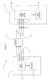
- FIG. 1 of the accompanying drawings is a schematic diagram illustrating a typical MIMO communication system 1 comprising a transmitting device 2 and a receiving device 14.
- a data source 4 provides an information symbol vector d to a MIMO encoder 8 which encodes the symbol vector d as T code symbols x 1 x 2 ..., x T .
- the T code symbols x 1 x 2 ..., x T can be represented as transmit symbol vector x , and in this example, T is three.
- the T code symbols x 1 x 2 ..., x T are then transmitted separately and simultaneously from T transmit antennas 6 respectively.
- An example of a MIMO encoder 8 is found by a direct mapping of input symbol d i to output symbol x i .
- a plurality R of receive antennas 18 receives respectively signals y 1 , ....y R , represented as symbol vector y.
- the channel conditions of the channel 12 between the transmitting device 2 and the receiving device 14 is represented by an R x T channel response matrix H (having R rows and T columns), with the noise contribution at the receiver being represented by the R -dimension noise vector v.
- y Hx + v.
- the receive signals y are then input to a MIMO detector and decoder 16, along with an estimate of the channel response matrix, H.
- Channel estimation in the MIMO detector 16 can be achieved in a number of well-documented ways.
- These inputs to the MIMO detector 16 can be used to form an estimate x and of the transmit symbol vector, or to directly form an estimate of the information symbol vector d .
- This estimate x and of the transmit symbol vector is then decoded by the MIMO decoder 16 by performing the reverse of the encoding operation performed by the MIMO encoder 8 to produce an estimate d and of the original information symbol vector d, and this estimate d and is passed to the data destination 22.
- Non-linear equalisers are more optimal and may employ maximum likelihood (ML) or maximum a posteriori probability (MAP) estimation techniques.
- data transmission over the channel 12 from multiple users can be handled using time division multiplexing in combination with the spatial multiplexing of MIMO so that the sequence of operations above is performed in one time frame for one user and for another user in the next time frame.
- the channel is frequency selective, this can be handled by using the OFDM (Orthogonal Frequency Division Multiplexing) technique.
- OFDM Orthogonal Frequency Division Multiplexing
- the bit stream is split into N parallel data streams at a rate of 1/N of the original rate.
- Each stream is modulated onto a unique tone and then combined to a single signal for transmission from a single antenna by means of an N-point inverse Fast Fourier Transform (IFFT).
- IFFT inverse Fast Fourier Transform
- the tones are orthogonal with adjacent ones and so do not interfere.
- Each block of N samples output from the IFFT is known as an OFDM symbol.
- a fixed number of additional samples are copied from the end of each OFDM symbol and pre-pended to it. This is known as a cyclic prefix (CP). Because this CP is designed to be longer than the greatest delay of the multipath channel response, inter symbol interference (ISI) is eliminated and the data on each sub-carrier experiences a narrowband flat fading channel response.
- a combined MIMO-OFDM system would operate similarly to the basic OFDM system described above where the system model for each sub-carrier can be expressed using equation (1) above. For each sub-carrier a different symbol vector, x , would be transmitted, a different signal vector, y, would be received, and a different channel response matrix, H , would be experienced. For example, if there were N sub-carriers, N MIMO-encoded transmit vectors would be generated. The N symbols corresponding to the first transmit antenna would be input to an IFFT and an OFDM symbol for the first transmit antenna created. This process would be repeated for each transmit antenna. The resultant T OFDM symbols would then be transmitted simultaneously over the multiple antennas of the MIMO system.
- Third generation mobile phone networks use a form of multiplexing known as CDMA (Code Division Multiple Access) spread spectrum signals for communicating across the radio interface between a mobile station and a base station.
- CDMA Code Division Multiple Access
- 3G networks are encompassed by the International Mobile Telecommunications IMT-2000 standard.
- Collectively the radio access portion of a 3G network is referred to as UTRAN (Universal Terrestrial Radio Access Network) and a network comprising UTRAN access networks is known as a UMTS (Universal Mobile Telecommunications System) network.
- the UMTS system is the subject of standards produced by the Third Generation Partnership Project (3GPP, 3GPP2), technical specifications for which can be found at www.3gpp.org.
- Fourth generation networks although not yet defined, may employ MIMO-based techniques.
- Multi-Carrier Code Division Multiple Access is similar to OFDM, but data symbols are first spread as for CDMA with a spreading code having a spreading factor SF (representing the number of chips per data bit). Multiple users can therefore be supported by each user employing a different spreading code.
- the SF chips are then allocated to SF adjacent sub-carriers of an OFDM system, i.e. with no spreading in time. This can result in the loss of orthogonality between spreading codes at a receiver, as each sub-carrier experiences a different channel gain.
- a suitable CP as for ordinary OFDM, eliminates inter symbol interference (ISI).
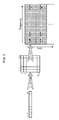
- Orthogonal Frequency Code Division Multiplexing is similar to MC-CDMA, but the chips resulting from spreading a single symbol can be arranged in blocks of frequency and time, so that each data symbol is allocated to a number of sub-carriers and a number of OFDM symbols on those sub-carriers.
- the dimensions of the block can be altered, for example the spreading can be SF in time and 1 in frequency, or vice versa, or some other combination making up SF chips.
- the overall spreading factor SF illustrated in the left-most portion is allocated with a spreading factor SF time in the time domain and SF freq in the frequency domain, as illustrated in the middle portion of Figure 2.
- the chips of the first symbol (Symbol 1) of user data are allocated across the first SF freq subcarriers and the first SF time OFDM symbols.
- the next symbol (Symbol 2) of user data is spread and allocated in a similar way, being allocated to the next SF freq subcarriers and the same SF time OFDM symbols. This is repeated until all the subcarners are filled with the user's data (with Symbol K occupying the final SF freq subcarriers).
- the SF time OFDM symbols can then be transmitted, and the next SF time OFDM symbols can then be allocated and transmitted in the same way.
- a single user data fills all subcarners (N / SF freq must be an integer, in this example equal to K).
- N / SF freq must be an integer, in this example equal to K).
- MC-CDMA can be described as an OFCDM system where symbols are always spread by a factor of SF in frequency and 1 in time.
- FIG. 3 of the accompanying drawings shows how the MIMO communication system 1 of Figure 1 can be modified to enable data from multiple users to be multiplexed according to the OFCDM scheme. To simplify the explanation, only the data from a single user will be illustrated; the data from other users is spread in frequency and time in a corresponding way and combined onto the same transmit signals described below.
- a data source 4 provides an information symbol vector d to a MIMO encoder 8 which encodes the symbol vector d to a T -dimensional symbol vector x.
- the symbol vector x is then processed by an OFCDM spreading portion 10 before transmission.
- the symbol vector x is spread in time to give a T x SF time transmit chip matrix X ( T rows and SF time columns), where SF time is the spreading factor in the time dimension.
- the transmit chip matrix X is also spread across SF freq adjacent frequency sub-carriers as described above and the various sub-carriers combined before transmission over the T transmit antennas 6.
- the response of the channel 12 between the transmitting device 2 and the receiving device 14, for a single sub-carrier is again represented by a R x T channel response matrix H ( R rows and T columns), with the noise contribution now being represented by a R x SF time matrix V.
- the received signals Y are then input to a MIMO detector 16-1.
- the MIMO detector 16-1 requires an estimate of the channel response matrix, H , which can be obtained using methods well known to someone skilled in the art.
- the estimates X and of the transmit chip matrix for each sub-carrier are then passed to an OFCDM despreading portion 20 which performs the reverse of the spreading performed by the OFCDM spreading portion 10, resulting in an estimate x and of the T -dimension symbol vector x.
- This estimate is then decoded by the MIMO decoder 16-2 by performing the reverse of the encoding operation performed by the MIMO encoder 8 to produce an estimate d and of the original data symbol vector d, and this estimate d and is passed to the data destination 22.
- the receiving device 14 conducts its antenna processing (channel estimation) separately on each sub-carrier, before despreading. This results in two principle disadvantages.
- the signal transmitted on each sub-carrier will contain the summation of chips from multiple users' symbols.
- the effective constellation is no longer that for a single symbol, but rather a composite constellation derived from the summation of multiple chips (symbols scaled by +1 or -1 in the case of binary spreading sequences), one for each user, vastly increasing the number of points.
- APP A Posteriori Probability
- VSF-OFCDM Variable Spreading Factor-Orthogonal Frequency and Code Division Multiplexing
- MC/DS-CDMA Multi-carner/DS-CDMA
- a communications method for use in a communications system comprising a transmitting device having at least T transmit antennas and a receiving device having at least R receive antennas, the method comprising: spreading each of T symbols in the time domain only to produce T time sequences of chips; transmitting the T time sequences of chips from the T transmit antennas respectively of the transmitting device; despreading each of R time sequences of chips received from the transmitting device at the R receive antennas of the receiving device respectively to produce R received symbols; processing the R received symbols to produce an estimate of the T symbols spread at the transmitting device.
- the T symbols are preferably each spread and the R time sequences of chips are preferably each despread based on the same user-specific spreading code, with each user of the communications system being allocated a different spreading code.
- the spreading codes allocated to each user are preferably orthogonal spreading codes.
- the T time sequences of chips may be modulated onto a sub-carrier prior to transmission .
- the sub-carrier may be a sub-carrier in an Orthogonal Frequency Division Multiplexing scheme.
- the communications system may be a Multiple Input Multiple Output, MIMO, system.
- the R received symbols may be processed using a MIMO detector.
- the T symbols may be MIMO-encoded symbols produced by a MIMO encoder for transmission from the T transmit antennas.
- the R received symbols may be processed in order to estimate the T symbols spread at the transmitting device using non-linear estimation techniques, such as the A Posteriori Probability technique. Or the R received symbols may be processed in order to estimate the T symbols spread at the transmitting device using linear estimation techniques.
- non-linear estimation techniques such as the A Posteriori Probability technique.
- the R received symbols may be processed in order to estimate the T symbols spread at the transmitting device using linear estimation techniques.
- a communications system comprising: a transmitting device comprising at least T transmit antennas, and means for spreading each of T symbols in the time domain only to produce T time sequences of chips, and transmitting the T time sequences of chips from the T transmit antennas respectively; and a receiving device comprising at least R receive antennas, means for despreading each of R time sequences of chips received from the transmitting device at the R receive antennas respectively to produce R received symbols; and means for processing the R received symbols to produce an estimate of the T symbols spread at the transmitting device.
- a communications method for use by a receiving device having at least R receive antennas in a communications system further comprising a transmitting device having at least T transmit antennas and operable to spread each of T symbols in the time domain only to produce T time sequences of chips and to transmit the T time sequences of chips from the T transmit antennas respectively, the method comprising: despreading each of R time sequences of chips received from the transmitting device at the R receive antennas of the receiving device respectively to produce R received symbols; processing the R received symbols to produce an estimate of the T symbols spread at the transmitting device.
- communications device for use in a communications system comprising a transmitting device having at least T transmit antennas and operable to spread each of T symbols in the time domain only to produce T time sequences of chips and to transmit the T time sequences of chips from the T transmit antennas respectively, the communications device comprising: at least R receive antennas, means for despreading each of R time sequences of chips received from the transmitting device at the R receive antennas of the receiving device respectively to produce R received symbols; and means for processing the R received symbols to produce an estimate of the T symbols spread at the transmitting device.
- an operating program which, when run on a communications device, causes the device to carry out a method according to the third aspect of the present invention.
- an operating program which, when loaded into a communications device, causes the device to become one according to the fourth aspect of the present invention.
- the operating program may be carried on a carrier medium, which may be a transmission medium or a storage medium.
- FIG 4 is a block diagram illustrating a communications system 101 according to an embodiment of the present invention.
- the communications system 101 embodying the present invention is similar in some respects to the communications system 1 described above with reference to Figure 3, but there are significant differences which will be described below.
- the communications system 101 embodying the present invention comprises a transmitting device 102 and a receiving device 114.
- the communications system 101 is based on the MIMO architecture, so that the transmitting device 102 comprises a plurality T of transmit antennas and the receiving device comprises a plurality R of receive antennas 118.
- T and R are both three.
- a data source 104 provides an information symbol vector d to a MIMO encoder 108 which encodes the symbol vector d as T code symbols x 1 x 2 ..., x T , which are represented as the symbol vector x.
- the symbol vector x is then processed by an OFCDM spreading portion 110 before transmission.
- Each of the T symbols in the symbol vector x is spread to a time sequence of chips, so that the symbol vector x is spread in time to produce a T x SF transmit chip matrix X ( T rows and SF columns), where SF is the spreading factor in the time domain.
- the T symbols in the symbol vector x are each spread based on a spreading code, with each user of the communications system 101 being allocated a different, orthogonal, spreading code.
- the T time sequences of chips contained in the transmit chip matrix X are separately modulated onto the first sub-carrier prior to transmission separately from the T respective transmit antennas 116. This is repeated, with a different transmit chip matrices, X, being modulated onto each of the remaining sub-carriers. All sub-carriers are then combined and transmitted simultaneously.
- the sub-carriers are sub-carriers in an Orthogonal Frequency Division Multiplex (OFDM) scheme. Therefore, at the transmitting device 102 at least, the communications system 101 operates according to a MIMO OFCDM scheme, but with spreading only in the time domain.
- OFDM Orthogonal Frequency Division Multiplex
- the channel response of the channel 112 between the transmitting device 2 and the receiving device 14 is represented by a R x T channel response matrix H ( R rows and T columns), with the noise contribution being represented by a R x SF matrix V .
- the received signals Y (effectively a matrix of R time sequences of chips) would then input to a MIMO detector 16-1 in order to descramble the MIMO channels and recover estimates of the chip sequences transmitted from the T transmit antennas 116.
- the MIMO detector 16-1 also requires an estimate of the channel response matrix, H, which can be obtained using methods well known to someone skilled in the art.
- This estimate x and would then be decoded in the prior art scheme by a MIMO decoder to produce an estimate d and of the original data symbol vector d .
- the R chip sequences in the chip matrix Y are passed to R separate despreading portions 120 1 120 2 , ... 120 R .
- the R symbols in the symbol vector z are then passed to the MIMO detector 116-1 to produce an estimate of the T data symbols in the symbol vector x transmitted from the transmit antennas 116.
- the symbol-level processing scheme embodying the present invention will be of increasing benefit as the number of antennas in the system increases. For these larger dimensional systems the antenna processing requirements at the receiving device can quickly become substantial or prohibitive, so a reduction in complexity of SF times will be all the more important.
- the MIMO detector 116-1 in an embodiment of the present invention is estimating symbols as opposed to chips, the MIMO detection process is no longer limited to the use of linear estimators as mentioned above in respect of the prior art system.
- Non-linear detectors such as the optimal A Posteriori Probability (APP) detector could be applied to the symbol vector z in order to obtain a better estimate of x and , and this can lead to an improvement in performance.
- APP A Posteriori Probability
- the linear estimator W in the above-described embodiment serves as an example of a MIMO detector
- this operation could (and probably would in practice) be replaced with another MIMO detector.
- This function could be a linear estimator such as W , or a successive interference cancellation detector such as the V-BLAST (Bell Labs Layered Space Time) algorithm, or an exhaustive search method such as the Maximum Likelihood (ML) or A Posteriori Probability (APP) detector.
- V-BLAST Bell Labs Layered Space Time
- APP A Posteriori Probability
- the input is just the received signal ( Y ), i.e. a matrix of chips, or the despread signal ( Yc T ), i.e. a vector of symbols.
- Processing the received signals according to an embodiment of the present invention allows any existing (or future) MIMO detection technique to be employed for OFCDM systems, as the output from the MIMO detection function will be in the form of symbols and not chips.
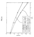
- the performance of a fully-loaded MEMO OFCDM system embodying the present invention should be identical to that of an equivalent MIMO OFDM system (i.e. without spreading at all).
- Such a performance comparison is provided in Figure 5 for a communications system having two transmit and two receive antennas.
- the vertical axis denotes the Bit Error Rate (BER) when employing an outer convolutional code
- the horizontal axis denotes the ratio of energy per information bit to noise variance.
- the graph comprises two groups of lines, with each group of lines comprising three closely-spaced but separate lines.
- the symbol-level processing scheme according to an embodiment of the present invention could use the APP detector instead in order to obtain the improved performance apparent from Figure 5.
- the results shown in Figure 5 are only for the symbol-level processing scheme, but the curves for chip-level processing with MMSE detection would be identical to the MMSE curves shown in Figure 5.
- operation of one or both of the transmitting device 102 and receiving device 114 can be controlled by a program operating on the device.
- Such an operating program can be stored on a computer-readable medium, or could, for example, be embodied in a signal such as a downloadable data signal provided from an Internet website.
- the appended claims are to be interpreted as covering an operating program by itself, or as a record on a carrier, or as a signal, or in any other form.
- An embodiment of the present invention can be applied to any communications system employing MIMO OFCDM, for example a mobile phone or base station in a mobile telecommunications system, or an access point or terminal in a wireless Local Area Network.
- MIMO OFCDM for example a mobile phone or base station in a mobile telecommunications system, or an access point or terminal in a wireless Local Area Network.
Landscapes
- Engineering & Computer Science (AREA)
- Signal Processing (AREA)
- Computer Networks & Wireless Communication (AREA)
- Radio Transmission System (AREA)
- Mobile Radio Communication Systems (AREA)
Applications Claiming Priority (2)
| Application Number | Priority Date | Filing Date | Title |
|---|---|---|---|
| GB0404451 | 2004-02-27 | ||
| GB0404451A GB2411550B (en) | 2004-02-27 | 2004-02-27 | Communications system, method and device |
Publications (2)
| Publication Number | Publication Date |
|---|---|
| EP1580919A1 true EP1580919A1 (de) | 2005-09-28 |
| EP1580919B1 EP1580919B1 (de) | 2008-08-20 |
Family
ID=32051037
Family Applications (1)
| Application Number | Title | Priority Date | Filing Date |
|---|---|---|---|
| EP05251150A Expired - Fee Related EP1580919B1 (de) | 2004-02-27 | 2005-02-25 | Funkkommunikationssysteme, -verfahren und -einrichtung für MIMO-Systeme mit Zeitbereichsspreiz |
Country Status (7)
| Country | Link |
|---|---|
| US (1) | US20050195913A1 (de) |
| EP (1) | EP1580919B1 (de) |
| JP (1) | JP2007522687A (de) |
| CN (1) | CN1839579A (de) |
| DE (1) | DE602005009056D1 (de) |
| GB (1) | GB2411550B (de) |
| WO (1) | WO2005083922A1 (de) |
Families Citing this family (2)
| Publication number | Priority date | Publication date | Assignee | Title |
|---|---|---|---|---|
| US20070223614A1 (en) * | 2006-03-23 | 2007-09-27 | Ravi Kuchibhotla | Common time frequency radio resource in wireless communication systems |
| JP5277673B2 (ja) * | 2008-03-17 | 2013-08-28 | 富士通株式会社 | 無線通信システム及び無線通信方法並びに送信装置及び受信装置 |
Citations (2)
| Publication number | Priority date | Publication date | Assignee | Title |
|---|---|---|---|---|
| WO2004040788A1 (en) * | 2002-11-01 | 2004-05-13 | Nokia Corporation | Data transmission method and transmitter |
| WO2004075436A1 (en) * | 2003-02-18 | 2004-09-02 | Samsung Electronics Co., Ltd. | A wireless transceiver and wireless transmitting/receiving method and program thereof |
Family Cites Families (8)
| Publication number | Priority date | Publication date | Assignee | Title |
|---|---|---|---|---|
| US20020159425A1 (en) * | 2000-03-17 | 2002-10-31 | Mitsuru Uesugi | Radio communication apparatus and radio communication method |
| US6731668B2 (en) * | 2001-01-05 | 2004-05-04 | Qualcomm Incorporated | Method and system for increased bandwidth efficiency in multiple input—multiple output channels |
| GB0120535D0 (en) * | 2001-08-23 | 2001-10-17 | Roke Manor Research | Space-time interleaving transmit diversity |
| CN1290281C (zh) * | 2001-11-10 | 2006-12-13 | 三星电子株式会社 | 正交频分复用移动通信系统中的空时频率块码编码/解码设备和方法 |
| US7020482B2 (en) * | 2002-01-23 | 2006-03-28 | Qualcomm Incorporated | Reallocation of excess power for full channel-state information (CSI) multiple-input, multiple-output (MIMO) systems |
| EP1488360A4 (de) * | 2002-02-21 | 2005-04-13 | Blue Martini Software Inc | Verfahren und systeme zur bereitstellung eines abgezielten marketings |
| EP1357693B1 (de) * | 2002-04-25 | 2010-06-09 | Imec | CDMA Empfang-übertragungstechniken für Funksysteme mit Mehrfacheingängen und Mehrfachausgängen (MIMO) |
| US20040116077A1 (en) * | 2002-08-08 | 2004-06-17 | Kddi Corporation | Transmitter device and receiver device adopting space time transmit diversity multicarrier CDMA, and wireless communication system with the transmitter device and the receiver device |
-
2004
- 2004-02-27 GB GB0404451A patent/GB2411550B/en not_active Expired - Fee Related
-
2005
- 2005-02-23 US US11/062,840 patent/US20050195913A1/en not_active Abandoned
- 2005-02-25 WO PCT/JP2005/003657 patent/WO2005083922A1/en not_active Ceased
- 2005-02-25 CN CNA2005800000161A patent/CN1839579A/zh active Pending
- 2005-02-25 JP JP2006524989A patent/JP2007522687A/ja not_active Withdrawn
- 2005-02-25 DE DE602005009056T patent/DE602005009056D1/de not_active Expired - Lifetime
- 2005-02-25 EP EP05251150A patent/EP1580919B1/de not_active Expired - Fee Related
Patent Citations (2)
| Publication number | Priority date | Publication date | Assignee | Title |
|---|---|---|---|---|
| WO2004040788A1 (en) * | 2002-11-01 | 2004-05-13 | Nokia Corporation | Data transmission method and transmitter |
| WO2004075436A1 (en) * | 2003-02-18 | 2004-09-02 | Samsung Electronics Co., Ltd. | A wireless transceiver and wireless transmitting/receiving method and program thereof |
Non-Patent Citations (3)
| Title |
|---|
| ATARASHI H ET AL: "Broadband packet wireless access based on VSF-OFCDM and MC/DS-CDMA", PERSONAL, INDOOR AND MOBILE RADIO COMMUNICATIONS, 2002. THE 13TH IEEE INTERNATIONAL SYMPOSIUM ON SEPT. 15-18, 2002, PISCATAWAY, NJ, USA,IEEE, vol. 3, 15 September 2002 (2002-09-15), pages 992 - 997, XP010611411, ISBN: 0-7803-7589-0 * |
| MAEDA N ET AL: "Antenna diversity reception appropriate for mmse combining in frequency domain for forward link OFCDM packet wireless access", SPREAD SPECTRUM TECHNIQUES AND APPLICATIONS, 2002 IEEE SEVENTH INTERNATIONAL SYMPOSIUM ON SEPT. 2-5, 2002, PISCATAWAY, NJ, USA,IEEE, vol. 2, 2 September 2002 (2002-09-02), pages 363 - 367, XP010615492, ISBN: 0-7803-7627-7 * |
| MATSUMOTO A ET AL: "A study on time domain spreading for OFCDM", WIRELESS PERSONAL MULTIMEDIA COMMUNICATIONS, 2002. THE 5TH INTERNATIONAL SYMPOSIUM ON OCT. 27-30, 2002, PISCATAWAY, NJ, USA,IEEE, vol. 2, 27 October 2002 (2002-10-27), pages 725 - 728, XP010619184, ISBN: 0-7803-7442-8 * |
Also Published As
| Publication number | Publication date |
|---|---|
| EP1580919B1 (de) | 2008-08-20 |
| JP2007522687A (ja) | 2007-08-09 |
| WO2005083922A1 (en) | 2005-09-09 |
| CN1839579A (zh) | 2006-09-27 |
| GB0404451D0 (en) | 2004-03-31 |
| GB2411550A (en) | 2005-08-31 |
| DE602005009056D1 (de) | 2008-10-02 |
| GB2411550B (en) | 2006-07-12 |
| US20050195913A1 (en) | 2005-09-08 |
Similar Documents
| Publication | Publication Date | Title |
|---|---|---|
| US7526038B2 (en) | Communications system, method and device | |
| KR100887909B1 (ko) | 다중 입력 다중 출력 채널에서 대역폭 효율의 증대를 위한방법 및 시스템 | |
| US8619920B2 (en) | Two-dimensional code spreading for interleaved FDMA system | |
| JP4346639B2 (ja) | 設定可能なブロックcdmaスキーム | |
| JP2014147082A (ja) | Sc−fdma伝送ダイバーシティのためのシステム及び方法 | |
| JP2007527150A (ja) | マルチアンテナ通信システムにおける空間拡散によるブロードキャスト送信 | |
| JP2007513554A (ja) | 線形プリコーディングされた信号のマルチアンテナ伝送方法、対応するデバイス、信号、および受信方法 | |
| EP2057758A1 (de) | Mehrantennen-scheduling-system und verfahren | |
| KR20050013611A (ko) | 데이터 수신 방법, 데이터 전송 방법, 수신기, 송신기,전송 시스템 및 컴퓨터 프로그램 제품 | |
| Nagatomi et al. | Complexity-reduced MLD based on QR decomposition in OFDM MIMO multiplexing with frequency domain spreading and code multiplexing | |
| JP2007208973A (ja) | ブロックcdmaシステムにおいて周波数ダイバーシティを増強する方法 | |
| JP4299302B2 (ja) | マルチキャリア信号を事前コード化するための装置及び方法 | |
| JP4483218B2 (ja) | 時空間送信ダイバーシチマルチキャリアcdma方式による受信装置並びに送信装置及び受信装置を備えた無線通信システム | |
| EP1580919B1 (de) | Funkkommunikationssysteme, -verfahren und -einrichtung für MIMO-Systeme mit Zeitbereichsspreiz | |
| Morales‐Jiménez et al. | Performance tradeoffs among low‐complexity detection algorithms for MIMO‐LTE receivers | |
| Chia et al. | Distributed DFT-Spread OFDM | |
| Sand et al. | Iterative channel estimation for high mobility broadband MC-CDMA systems | |
| Munster et al. | Performance of SDMA multiuser detection techniques for Walsh-Hadamard-spread OFDM schemes | |
| Doostnejad et al. | On spreading codes for the down-link in a multiuser MIMO/OFDM system | |
| Kim et al. | Performance analysis of a downlink MIMO MC-CDMA system with turbo coding and channel interleaving | |
| Kawamoto et al. | Independent turbo coding and common interleaving method among transmitter branches achieving peak throughput of 1 Gbps in OFCDM MIMO multiplexing | |
| Feng et al. | Blind space-time equalization/decoding with carrier frequency synchronization in multicarrier CDMA systems | |
| KR101019172B1 (ko) | V-blast ofdm 방식을 사용하는 통신시스템에서의데이터 송/수신장치 및 방법 | |
| Horlin et al. | Flexible transmission scheme for 4G wireless systems with multiple antennas | |
| Witschnig et al. | Antenna Diversity Techniques for SC/FDE—a System Analysis |
Legal Events
| Date | Code | Title | Description |
|---|---|---|---|
| PUAI | Public reference made under article 153(3) epc to a published international application that has entered the european phase |
Free format text: ORIGINAL CODE: 0009012 |
|
| 17P | Request for examination filed |
Effective date: 20050317 |
|
| AK | Designated contracting states |
Kind code of ref document: A1 Designated state(s): AT BE BG CH CY CZ DE DK EE ES FI FR GB GR HU IE IS IT LI LT LU MC NL PL PT RO SE SI SK TR |
|
| AX | Request for extension of the european patent |
Extension state: AL BA HR LV MK YU |
|
| AKX | Designation fees paid |
Designated state(s): DE FR |
|
| 17Q | First examination report despatched |
Effective date: 20070206 |
|
| GRAP | Despatch of communication of intention to grant a patent |
Free format text: ORIGINAL CODE: EPIDOSNIGR1 |
|
| GRAS | Grant fee paid |
Free format text: ORIGINAL CODE: EPIDOSNIGR3 |
|
| GRAA | (expected) grant |
Free format text: ORIGINAL CODE: 0009210 |
|
| AK | Designated contracting states |
Kind code of ref document: B1 Designated state(s): DE FR |
|
| REF | Corresponds to: |
Ref document number: 602005009056 Country of ref document: DE Date of ref document: 20081002 Kind code of ref document: P |
|
| PLBE | No opposition filed within time limit |
Free format text: ORIGINAL CODE: 0009261 |
|
| STAA | Information on the status of an ep patent application or granted ep patent |
Free format text: STATUS: NO OPPOSITION FILED WITHIN TIME LIMIT |
|
| 26N | No opposition filed |
Effective date: 20090525 |
|
| PGFP | Annual fee paid to national office [announced via postgrant information from national office to epo] |
Ref country code: DE Payment date: 20130220 Year of fee payment: 9 Ref country code: FR Payment date: 20130301 Year of fee payment: 9 |
|
| REG | Reference to a national code |
Ref country code: DE Ref legal event code: R119 Ref document number: 602005009056 Country of ref document: DE |
|
| REG | Reference to a national code |
Ref country code: FR Ref legal event code: ST Effective date: 20141031 |
|
| REG | Reference to a national code |
Ref country code: DE Ref legal event code: R119 Ref document number: 602005009056 Country of ref document: DE Effective date: 20140902 |
|
| PG25 | Lapsed in a contracting state [announced via postgrant information from national office to epo] |
Ref country code: FR Free format text: LAPSE BECAUSE OF NON-PAYMENT OF DUE FEES Effective date: 20140228 Ref country code: DE Free format text: LAPSE BECAUSE OF NON-PAYMENT OF DUE FEES Effective date: 20140902 |