EP1580853B1 - Halbleiterlaser und Herstellungsverfahren - Google Patents
Halbleiterlaser und Herstellungsverfahren Download PDFInfo
- Publication number
- EP1580853B1 EP1580853B1 EP05010646A EP05010646A EP1580853B1 EP 1580853 B1 EP1580853 B1 EP 1580853B1 EP 05010646 A EP05010646 A EP 05010646A EP 05010646 A EP05010646 A EP 05010646A EP 1580853 B1 EP1580853 B1 EP 1580853B1
- Authority
- EP
- European Patent Office
- Prior art keywords
- layer
- plane
- type cladding
- conduction type
- cladding layer
- Prior art date
- Legal status (The legal status is an assumption and is not a legal conclusion. Google has not performed a legal analysis and makes no representation as to the accuracy of the status listed.)
- Expired - Lifetime
Links
Images


Classifications
-
- H10P14/2911—
-
- B—PERFORMING OPERATIONS; TRANSPORTING
- B82—NANOTECHNOLOGY
- B82Y—SPECIFIC USES OR APPLICATIONS OF NANOSTRUCTURES; MEASUREMENT OR ANALYSIS OF NANOSTRUCTURES; MANUFACTURE OR TREATMENT OF NANOSTRUCTURES
- B82Y20/00—Nanooptics, e.g. quantum optics or photonic crystals
-
- H—ELECTRICITY
- H01—ELECTRIC ELEMENTS
- H01S—DEVICES USING THE PROCESS OF LIGHT AMPLIFICATION BY STIMULATED EMISSION OF RADIATION [LASER] TO AMPLIFY OR GENERATE LIGHT; DEVICES USING STIMULATED EMISSION OF ELECTROMAGNETIC RADIATION IN WAVE RANGES OTHER THAN OPTICAL
- H01S5/00—Semiconductor lasers
- H01S5/20—Structure or shape of the semiconductor body to guide the optical wave ; Confining structures perpendicular to the optical axis, e.g. index or gain guiding, stripe geometry, broad area lasers, gain tailoring, transverse or lateral reflectors, special cladding structures, MQW barrier reflection layers
- H01S5/22—Structure or shape of the semiconductor body to guide the optical wave ; Confining structures perpendicular to the optical axis, e.g. index or gain guiding, stripe geometry, broad area lasers, gain tailoring, transverse or lateral reflectors, special cladding structures, MQW barrier reflection layers having a ridge or stripe structure
- H01S5/223—Buried stripe structure
- H01S5/2238—Buried stripe structure with a terraced structure
-
- H10P14/24—
-
- H10P14/2925—
-
- H10P14/2926—
-
- H10P14/3218—
-
- H10P14/3221—
-
- H10P14/3251—
-
- H10P14/3421—
-
- H10P14/3442—
-
- H—ELECTRICITY
- H01—ELECTRIC ELEMENTS
- H01S—DEVICES USING THE PROCESS OF LIGHT AMPLIFICATION BY STIMULATED EMISSION OF RADIATION [LASER] TO AMPLIFY OR GENERATE LIGHT; DEVICES USING STIMULATED EMISSION OF ELECTROMAGNETIC RADIATION IN WAVE RANGES OTHER THAN OPTICAL
- H01S2301/00—Functional characteristics
- H01S2301/17—Semiconductor lasers comprising special layers
- H01S2301/173—The laser chip comprising special buffer layers, e.g. dislocation prevention or reduction
-
- H—ELECTRICITY
- H01—ELECTRIC ELEMENTS
- H01S—DEVICES USING THE PROCESS OF LIGHT AMPLIFICATION BY STIMULATED EMISSION OF RADIATION [LASER] TO AMPLIFY OR GENERATE LIGHT; DEVICES USING STIMULATED EMISSION OF ELECTROMAGNETIC RADIATION IN WAVE RANGES OTHER THAN OPTICAL
- H01S2304/00—Special growth methods for semiconductor lasers
- H01S2304/04—MOCVD or MOVPE
-
- H—ELECTRICITY
- H01—ELECTRIC ELEMENTS
- H01S—DEVICES USING THE PROCESS OF LIGHT AMPLIFICATION BY STIMULATED EMISSION OF RADIATION [LASER] TO AMPLIFY OR GENERATE LIGHT; DEVICES USING STIMULATED EMISSION OF ELECTROMAGNETIC RADIATION IN WAVE RANGES OTHER THAN OPTICAL
- H01S5/00—Semiconductor lasers
- H01S5/20—Structure or shape of the semiconductor body to guide the optical wave ; Confining structures perpendicular to the optical axis, e.g. index or gain guiding, stripe geometry, broad area lasers, gain tailoring, transverse or lateral reflectors, special cladding structures, MQW barrier reflection layers
- H01S5/22—Structure or shape of the semiconductor body to guide the optical wave ; Confining structures perpendicular to the optical axis, e.g. index or gain guiding, stripe geometry, broad area lasers, gain tailoring, transverse or lateral reflectors, special cladding structures, MQW barrier reflection layers having a ridge or stripe structure
- H01S5/2201—Structure or shape of the semiconductor body to guide the optical wave ; Confining structures perpendicular to the optical axis, e.g. index or gain guiding, stripe geometry, broad area lasers, gain tailoring, transverse or lateral reflectors, special cladding structures, MQW barrier reflection layers having a ridge or stripe structure in a specific crystallographic orientation
-
- H—ELECTRICITY
- H01—ELECTRIC ELEMENTS
- H01S—DEVICES USING THE PROCESS OF LIGHT AMPLIFICATION BY STIMULATED EMISSION OF RADIATION [LASER] TO AMPLIFY OR GENERATE LIGHT; DEVICES USING STIMULATED EMISSION OF ELECTROMAGNETIC RADIATION IN WAVE RANGES OTHER THAN OPTICAL
- H01S5/00—Semiconductor lasers
- H01S5/30—Structure or shape of the active region; Materials used for the active region
- H01S5/305—Structure or shape of the active region; Materials used for the active region characterised by the doping materials used in the laser structure
- H01S5/3054—Structure or shape of the active region; Materials used for the active region characterised by the doping materials used in the laser structure p-doping
-
- H—ELECTRICITY
- H01—ELECTRIC ELEMENTS
- H01S—DEVICES USING THE PROCESS OF LIGHT AMPLIFICATION BY STIMULATED EMISSION OF RADIATION [LASER] TO AMPLIFY OR GENERATE LIGHT; DEVICES USING STIMULATED EMISSION OF ELECTROMAGNETIC RADIATION IN WAVE RANGES OTHER THAN OPTICAL
- H01S5/00—Semiconductor lasers
- H01S5/30—Structure or shape of the active region; Materials used for the active region
- H01S5/34—Structure or shape of the active region; Materials used for the active region comprising quantum well or superlattice structures, e.g. single quantum well [SQW] lasers, multiple quantum well [MQW] lasers or graded index separate confinement heterostructure [GRINSCH] lasers
- H01S5/343—Structure or shape of the active region; Materials used for the active region comprising quantum well or superlattice structures, e.g. single quantum well [SQW] lasers, multiple quantum well [MQW] lasers or graded index separate confinement heterostructure [GRINSCH] lasers in AIIIBV compounds, e.g. AlGaAs-laser, InP-based laser
- H01S5/34326—Structure or shape of the active region; Materials used for the active region comprising quantum well or superlattice structures, e.g. single quantum well [SQW] lasers, multiple quantum well [MQW] lasers or graded index separate confinement heterostructure [GRINSCH] lasers in AIIIBV compounds, e.g. AlGaAs-laser, InP-based laser with a well layer based on InGa(Al)P, e.g. red laser
-
- H—ELECTRICITY
- H01—ELECTRIC ELEMENTS
- H01S—DEVICES USING THE PROCESS OF LIGHT AMPLIFICATION BY STIMULATED EMISSION OF RADIATION [LASER] TO AMPLIFY OR GENERATE LIGHT; DEVICES USING STIMULATED EMISSION OF ELECTROMAGNETIC RADIATION IN WAVE RANGES OTHER THAN OPTICAL
- H01S5/00—Semiconductor lasers
- H01S5/30—Structure or shape of the active region; Materials used for the active region
- H01S5/34—Structure or shape of the active region; Materials used for the active region comprising quantum well or superlattice structures, e.g. single quantum well [SQW] lasers, multiple quantum well [MQW] lasers or graded index separate confinement heterostructure [GRINSCH] lasers
- H01S5/343—Structure or shape of the active region; Materials used for the active region comprising quantum well or superlattice structures, e.g. single quantum well [SQW] lasers, multiple quantum well [MQW] lasers or graded index separate confinement heterostructure [GRINSCH] lasers in AIIIBV compounds, e.g. AlGaAs-laser, InP-based laser
- H01S5/34346—Structure or shape of the active region; Materials used for the active region comprising quantum well or superlattice structures, e.g. single quantum well [SQW] lasers, multiple quantum well [MQW] lasers or graded index separate confinement heterostructure [GRINSCH] lasers in AIIIBV compounds, e.g. AlGaAs-laser, InP-based laser characterised by the materials of the barrier layers
- H01S5/3436—Structure or shape of the active region; Materials used for the active region comprising quantum well or superlattice structures, e.g. single quantum well [SQW] lasers, multiple quantum well [MQW] lasers or graded index separate confinement heterostructure [GRINSCH] lasers in AIIIBV compounds, e.g. AlGaAs-laser, InP-based laser characterised by the materials of the barrier layers based on InGa(Al)P
Definitions
- the present invention relates to a semiconductor laser and a method of manufacturing the same and, more particularly, to a self-aligned stepped substrate (S 3 ) type semiconductor laser and a method of manufacturing the same.
- FIG.1 of the accompanying drawings The structure of a previously-proposed S 3 type semiconductor laser is shown in FIG.1 of the accompanying drawings.
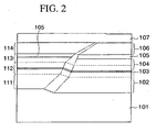
- an n-type cladding layer 102 formed of n-AlGaInP, a strained quantum well active layer 103, a first p-type cladding layer 104 formed of p-AlGaInP, a pn alternatively-doped (current) blocking layer 105 formed of AlGaInP, a second p-type cladding layer 106 formed of p-AlGaInP, and a contact layer 107 formed of p-GaAs are formed in sequence on an n-GaAs substrate 101 on which a step 101a having an inclined plane is formed.
- Respective layers 102 to 107 on the n-GaAs substrate 101 have an inclined plane that is almost parallel with the inclined plane of the step 101a respectively.
- the alternatively-doped blocking layer 105 is formed due to the property that the n-type impurity is incorporated readily into the flat portion when the p-type impurity and the n-type impurity are supplied alternatively in growing.
- the p-type impurity is incorporated preferentially into the portion that is parallel with the inclined plane of the step 101a of the AlGaInP layer constituting the alternatively-doped blocking layer 105 to thus form the p-type cladding layer 104.
- the n-type cladding layer 102 and the p-type cladding layers 104, 106 are divided into first to fourth layer regions 111 to 114 by broken lines.
- the first to fourth layer regions 111 to 114 are portions in which a ratio of the flow rate of the group V material gas to the flow rate of the group III material gas (referred to as a "V/III ratio" hereinafter) is changed respectively or portions in which the growth temperature is changed respectively.
- first and fourth layer regions 111, 114 are the portions that are formed by the high V/III ratio or at the low growth temperature
- the second and third layer regions 112, 113 are the portions that are formed by the low V/III ratio or at the high growth temperature.
- V/III ratio acts to change lines that define the flat portions and the step portions of the cladding layers 102, 104, 106, i.e., respective profiles of boundary lines between the flat surfaces and the inclined planes of the first to fourth layer regions 111 to 114 (referred to as "growth profiles" hereinafter).
- growth profiles i.e., respective profiles of boundary lines between the flat surfaces and the inclined planes of the first to fourth layer regions 111 to 114.
- dot-dash lines denote growth profile lines indicating the change of the growth profile.
- an angle ⁇ between the flat portion and the growth profile line is small in the portions which are grown by the high V/III ratio, and this angle ⁇ exhibits a tendency to increase as the V/III ratio is lowered.
- an angle ⁇ 01 of the growth profile line of the first layer region 111 is smaller than an angle ⁇ 02 of the growth profile line of the second layer region 112, and an angle ⁇ 03 of the growth profile line of the third layer region 113 is larger than an angle ⁇ 04 of the growth profile line of the fourth layer region 114.
- the angle ⁇ between the flat portion and the growth profile line affects the polarization plane of the laser beam in the laser oscillation and that the polarization plane becomes substantially perpendicular to the growth line.
- the polarization plane should be set in the parallel direction with the inclined plane of the active layer 103. That is, the angle ⁇ must be set to about 90 degrees to the inclined plane of the active layer 103.
- the portions that have large influence on the polarization plane and are close to the active layer 103 are grown at the low V/III ratio to form their growth profile lines substantially perpendicularly to the inclined plane of the active layer 103, and also the polarization planes are set in parallel with the inclined plane portion of the active layer 103 by growing the portions that have small influence on the polarization plane and are far from the active layer 103 at the high V/III ratio.
- the inclined plane (step portion) of the active layer 103 is referred to as a stripe portion hereinafter.
- the reason that all the cladding layers 102, 104, 106 are not grown at the low V/III ratio is that, if the layer growth is carried out at the boundary portion between the n-GaAs substrate 101 and the GaAs contact layer 107 at the low V/III ratio, the crystal defect is ready to generate at the boundary portion between them and therefore such defect should be prevented.
- the optical output required for the semiconductor laser is increased year by year.
- the transverse mode of the laser becomes unstable.
- both the second and third layer regions 112, 113 are grown at the low V/III ratio.
- the second layer region 112 corresponds to the transition region that causes the growth profile lines to be formed in parallel
- the third layer region 113 corresponds to the stable region that appears after the transition region is completed.
- the active layer 103 is formed in the second layer region 112 serving as the transition region.
- Major approaches are to narrow the stripe portion further and to strengthen the symmetrization of the growth profiles on both sides of the active layer 103.
- FIG.2 of the accompanying drawings shows a schematic sectional view obtained when the narrower stripe formation and the growth profile symmetrization strengthening of the active layer are carried out by employing the technology in the prior art.
- the active layer 103 in order to strengthen the symmetrization of the active layer growth profiles, the active layer 103 is provided in the center portion of the transition region that is grown at the low V/III ratio. Accordingly, two growth profile lines on both sides of the stripe portion of the active layer 103 become parallel.
- the first problem is that the polarization plane of the laser beam output from the semiconductor laser is ready to rotate.
- the low V/III ratio transition region 112 formed on the first layer region 111 serving as the high V/III ratio growth layer does not appear to have a thickness of about 0.5 ⁇ m or more. Therefore, if this transition region is assigned to upper and lower portions of the active region 103, only the thickness of about 0.25 ⁇ m can be given on one side.
- the n-type cladding layer 102 needs the thickness of about 1.5 ⁇ m at least and therefore an occupying rate of the high V/III ratio layer region 111 in the n-type cladding layer 102 becomes high. As the result, it is impossible to maintain the polarization plane of the laser beam in parallel with the stripe portion of the active layer 103.
- the second problem is that a width between the right and left blocking layers 105 formed between the first p-type cladding layer 104 and the second p-type cladding layer 106 is narrowed because of the narrower stripe formation, and thus the device resistance is increased.
- the blocking layer 105 in the previous proposal is formed in the stabilized region that is grown at the low V/III ratio and serves as the third layer region 113. In this stabilized region, the growth profile lines are formed like the " ⁇ " character as the layer thickness is increased, and thus there is the strong tendency that a width of the inclined surface of the p-type cladding layer 104 is reduced. As a result, the resistance increase of the p-type cladding layer 104 between the current blocking layers 105 formed on the upper end of the third layer region 113 is remarkable.
- US-A-5 862 166 discloses a stepped substrate semiconductor (S 3 ) laser (fig. 11) having an n-type stepped substrate (60), n-type cladding layers (61 - 63), an active layer (64), p-type layers (65, 66) and a p-n alternately doped layer (67a, 67b) serving as a p-type layer (67a) along the inclined portions and as an n-type current blocking layers (67b) in the regions oriented along the principal planes, wherein, in the perpendicular plane to the travelling direction of light, if the angle between the first growth profile line of the first p-type cladding layer (65) and the first principal plane is ⁇ 11 , and the angle between the second growth profile line of the second p-type cladding layer (67) and the first principal plane is ⁇ 12 , ⁇ 11 > ⁇ 12 is satisfied.
- P-type layer (66) with the smaller growth profile angle ⁇ 12 is provided
- One embodiment of a first aspect of the present invention can provide a semiconductor laser comprising a first conduction type stepped substrate having first principal planes exposing a (100) plane or a (n11) A plane with n ⁇ 7, where n is a real number, and a first inclined plane exposing a (n 1 11) A plane with 2 ⁇ n 1 ⁇ 7, where n 1 is a real number; first conduction type cladding layer formed on the stepped substrate; an active layer formed on the first conduction type cladding layer, and having a second principal planes exposing a (100) plane or a (n11) A plane with n ⁇ 7, where n is a real number, and a second inclined plane exposing a (n 2 11) A plane with 2 ⁇ n 2 ⁇ 7, where n 2 is a real number, over the first principal planes; a first layer of a second conduction type cladding layer formed on the active layer; and a pn alternately-doped layer formed on and in
- the current blocking regions are formed on both sides of the inclined plane in the bottom region of the second conduction type cladding layer in which the angle of the growth profile line is small.
- the inclination of the growth profile line of the second conduction type cladding layer that is formed along the inclined plane of the active layer and is put between the current blocking regions becomes small, but the growth profile of the region between the current blocking regions holds the almost same width even if the layer thickness is increased. Therefore, even if the stripe portion is formed as the narrow stripe, the second conduction type cladding layer between the current blocking regions is not narrowed and also the device electric resistance is reduced. The reduction of the device electric resistance prevents the kink level of the output characteristic deteriorating.
- the method of growing the current blocking regions in the stable regions having the low V/III ratio is not used, but the method of forming the current blocking regions at the high V/III ratio or the low growth temperature is employed.
- the angles of the growth profile lines on the side portions of the inclined plane become small, nevertheless the tendency that the width of the stripe-portion is reduced as the layer thickness is increased is small in contrast to using the stable region growth that is carried out at the low V/III ratio or the high growth temperature. Therefore, the low V/III ratio growth is switched to the high V/III ratio growth in the thin thickness stage of the low V/III ratio stable growth, wherein the reduction in the width of the stripe-portion is not conspicuous, and then the increase of the device resistance can be prevented by forming the current blocking regions under these conditions by the pn alternative doping.
- One embodiment of a second aspect of the invention can provide a semiconductor laser manufacturing method comprising the steps of: forming first conduction type cladding layer on a stepped substrate having a first inclined plane exposing a (n 1 11) A plane with 2 ⁇ n 1 ⁇ 7, where n 1 is a real number, and first principal planes exposing a (100) plane or a (n11) A plane with n ⁇ 7, where n is a real number, on both sides of the first inclined plane; forming an active layer, that has second principal planes exposing the (100) plane or the (n11) A plane with n ⁇ 7, where n is a real number, over the first principal planes and a second inclined plane exposing a (n 2 11) A plane with 2 ⁇ n 2 ⁇ 7, where n 2 is a real number, on a first conduction type cladding layer; forming a first layer of the second conduction type cladding layer on the active layer by setting a V/III ratio, that is a ratio of
- One embodiment of a third aspect of the invention can provide a semiconductor laser manufacturing method comprising the steps of: forming first conduction type cladding layer on a stepped substrate having a first inclined plane exposing a (n 1 11) A plane with 2 ⁇ n 1 ⁇ 7, where n 1 is a real number, and first principal planes exposing a (100) plane or a (n11) A plane with n ⁇ 7, where n is a real number, on both sides of the first inclined plane; forming an active layer, that has second principal planes exposing the (100) plane or the (n11) A plane with n ⁇ 7, where n is a real number, over the first principal planes and a second inclined plane exposing a (n 2 11) A plane with 2 ⁇ n 2 ⁇ 7, where n 2 is a real number, on the first conduction type cladding layer; forming a first layer of the second conduction type cladding layer on the active layer by setting a growth temperature to a first value; forming a second
- the first conduction type cladding layers which is formed under the active layer are formed on the stepped plane of the substrate to have the at least quadruple-layered structure, and the angle of the growth profile line of the inclined plane of the uppermost first conduction type cladding layer to the flat principal plane is enhanced by changing the angles of the growth profile lines of the inclined planes of the first conduction type cladding layers to the principal plane so as to repeat small, large, small, and large.
- the angle of the growth profile line of the inclined plane of the first conduction type cladding layer that is formed just under the active layer can be set substantially perpendicular to the stripe-portion of the active layer.
- at least two layers that have the growth profile line at the angle that is substantially perpendicular to the stripe-portion of the active layer are provided alternately in the first conduction type cladding layers. Therefore, in the first conduction type cladding layers, a total layer thickness of the layers which have the growth profile line that do not become substantially perpendicular to the stripe-portion of the active layer can be reduced rather than the prior art. As a result, the rotation of the polarization plane of the laser beam is suppressed and thus the kink level of the output characteristic of the semiconductor laser is held high.
- an n-GaAs substrate 1 whose principal plane is off from a (100) plane by an angle of 6 degrees toward a (111) A plane and which has a diameter of 2 inch is prepared.
- the silicon as the n-type impurity is doped into the n-GaAs substrate 1 at the concentration of about 4 ⁇ 10 18 cm -3 .
- a level difference is formed on the principal plane by forming a stripe-like resist (not shown) on the principal plane of the n-GaAs substrate 1 and then etching the portion that is not covered with the resist up to a depth of about 0.5 ⁇ m by using the hydrogen fluoride-containing solution.
- the principal plane that is covered with the resist is defined as an upper principal plane 1a and the principal plane that appears by the etching is defined as a lower principal plane 1b
- a inclined plane 1c that has a plane direction of about (411) A plane and has a width of about 1.15 ⁇ m is formed at the boundary between the upper principal plane 1a and the lower principal plane 1b.
- This inclined plane 1c is formed like a stripe that extends in a ⁇ 011> direction, for example.
- the resist is removed from the n-GaAs substrate 1, and then a buffer layer 2 formed of n-GaAs and having a thickness of 1.0 ⁇ m is formed on the upper principal plane 1a, the lower principal plane 1b, and the inclined plane 1c of the n-GaAs substrate 1.
- a buffer layer 2 formed of n-GaAs and having a thickness of 1.0 ⁇ m is formed on the upper principal plane 1a, the lower principal plane 1b, and the inclined plane 1c of the n-GaAs substrate 1.
- a inclined plane 2a with the plane direction of about (411) A plane appears on the inclined plane 1c of the n-GaAs substrate 1.
- the GaAs layer constituting the buffer layer 2 is formed by the MOVPE method using triethylgallium (TEGa: Ga(C 2 H 5 ) 3 ) as the gallium material gas and arsine (AsH 3 ) as the arsenic material gas.
- TMGa triethylgallium
- AsH 3 arsine
- the growth rate is set to 1 ⁇ m/hour and the V/III ratio is set to 100.
- the n-type impurity is introduced by using disilane (Si 2 H 6 ) as the n-type dopant material.
- the n-type impurity concentration in the buffer layer 2 is set to about 5 ⁇ 10 17 cm -3 .
- a plurality of layers from the buffer layer 2 to a contact layer 14 described later are formed continuously as a whole by the MOVPE method under the conditions of the substrate temperature 680 °C, the growth atmospheric pressure 50 Torr, the growth efficiency 80 ⁇ m/mol, and the total gas flow rate 8 sim.
- the source gas to grow these layers is supplied to the growth atmosphere by using hydrogen as the carrier gas.
- a lower intermediate layer 3 formed of GaInP and having a layer thickness of 0.1 ⁇ m is formed on the buffer layer 2.
- This GaInP is formed under the conditions of the V/III ratio 500 and the growth rate 1 ⁇ m/hour.
- TEGa and trimethylindium (TMIn: In(CH 3 ) 3 ) are used as the group III source gas and also phosphine (PH 3 ) is used as the group V source gas.
- PH 3 phosphine
- disilane is used as the n-type dopant to set the impurity concentration in the lower intermediate layer 3 to about 1 ⁇ 10 18 cm -3 .
- a inclined plane 3a that is parallel with the inclined plane 2a of the buffer layer 2 is formed in the lower intermediate layer 3.
- first to fourth n-type cladding layers 4 to 7 formed of n-AlGaInP are formed in sequence on the lower intermediate layer 3 while changing the conditions.
- a layer thickness of the first n-type cladding layer 4 is 0.3 ⁇ m
- a layer thickness of the second n-type cladding layer 5 is 1.0 ⁇ m
- a layer thickness of the third n-type cladding layer 6 is 0.3 ⁇ m
- a layer thickness of the fourth n-type cladding layer 7 is 0.25 ⁇ m.
- trimetylalluminum (TMAl: Al(CH 3 ) 3 ), TEGa, and TMIn are used as the group III source gas, and phosphine is used as the group V source gas, and also disilane is used as the n-type dopant.
- the n-type impurity concentration in the first to fourth n-type cladding layers 4 to 7 is set to 5 ⁇ 10 17 cm -3 .
- the first to fourth n-type cladding layers 4 to 7 have upper inclined planes 4a to 7a that are almost parallel with the inclined plane 1c of the n-GaAs substrate 1 respectively and also have flat surfaces that are parallel with the principal planes 1a, 1b of the n-GaAs substrate 1 and connected to these inclined planes 4a to 7a respectively.
- the V/III ratio is set high like 270 to grow the first n-type cladding layer 4, the V/III ratio is set low like 110 to grow the second n-type cladding layer 5, the V/III ratio is set high like 270 to grow the third n-type cladding layer 6, and the V/III ratio is set low like 110 to grow the fourth n-type cladding layer 7.
- first to fourth n-type cladding layers 4 to 7 are grown continuously while changing the V/III ratio in this manner, profiles of the boundary lines between the flat surfaces and the inclined planes 4a to 7a in the first to fourth n-type cladding layers 4 to 7 (growth profiles) are changed, respectively.
- the lower growth profile line of the first n-type cladding layer 4 is a line connecting a lower side line of the inclined plane 4a of the first n-type cladding layer 4 and a lower side line of the inclined plane 3a.
- the lower growth profile lines of the second to fourth n-type cladding layers 5 to 7 are defined.
- the upper growth profile line of the first n-type cladding layer 4 is a line connecting an upper side line of the inclined plane 4a of the first n-type cladding layer 4 and an upper side line of the inclined plane 3a.
- the upper growth profile lines of the second to fourth n-type cladding layers 5 to 7 are defined.
- the region reaching a thickness of about 0.5 ⁇ m from the start of growth acts as the transition region, and its lower growth profile line and its upper growth profile line become almost perpendicular to the inclined plane 5a, and the region reaching a subsequent thickness of about 0.5 ⁇ m acts as the stable region, and an interval of the growth profile lines on both sides of the inclined plane 5a becomes slightly narrow.
- the first n-type cladding layer 4 and the third n-type cladding layer 6 are formed at the high V/III ratio, and their angles ⁇ 1 , ⁇ 3 between the growth profile lines on both sides of these inclined planes 4a, 6a and the inclined planes 4a, 6a are not substantially a right angle.
- a total layer thickness of the first and third n-type cladding layers 4, 6 is about 0.6 ⁇ m that is about 32 % of the overall layer thickness of the n-type cladding layers 4 to 7, and is smaller than that in the prior art. Therefore, it is possible to eliminate the situation that the first and third n-type cladding layers 4, 6 having the growth profile lines with such inclination rotate the polarization plane of the laser beam.
- the lower growth profile line and the upper growth profile line of the fourth n-type cladding layer 7 have a substantially right angle (perpendicular) to the inclined plane 7a.
- the "substantially right angle” means an angle that is contained within the range of ⁇ 15 degrees, preferably ⁇ 10 degrees, from 90 degrees.
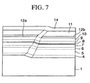
- a strained quantum well active layer 8 is formed on the fourth n-type cladding layer 7 and then a first p-type cladding layer 9 and a second p-type cladding layer 10 are formed sequentially thereon.
- the strained quantum well active layer 8 has a stripe-like upper inclined plane 8a that is parallel with the inclined plane 7a of the fourth n-type cladding layer 7 and has a width of 1.15 ⁇ m. Also, the first and second p-type cladding layers 9, 10 have upper inclined planes 9a, 10a that are parallel with the inclined plane 8a of the strained quantum well active layer 8 respectively.
- the strained quantum well active layer 8 has a first barrier layer 8b, a first well layer 8c, a second barrier layer 8d, a second well layer 8e, a third barrier layer 8f, a third well layer 8g, and a fourth barrier layer 8h, which are formed in sequence on the fourth n-type cladding layer 7, for example.
- the first to fourth barrier layers 8b, 8d, 8f, 8h are formed of a (Al 0.5 Ga 0.5 ) 0.5 In 0.5 P layer that is formed at the growth rate 1 ⁇ m /hour and has a layer thickness of 5 nm.
- TMA1, TEGa, and TMIn are employed as the group III source gas and phosphine is employed as the group V source gas.
- the first to third well layers 8c, 8e, 8g are formed of a Ga 0.42 In 0.58 P layer that is formed at the V/III ratio 330 and the growth rate 1 ⁇ m /hour and has a layer thickness of 5 nm.
- TEGa and TMIn are employed as the group III source gas and phosphine is employed as the group V source gas.
- the strained quantum well active layer 8 does not have the advantage that can change the growth profile as the high V/III ratio layer since its layer thickness is thin.
- both the first p-type cladding layer 9 and the second p-type cladding layer 10 are formed of a p-AlGaInP layer that is formed at the V/III ratio 110 and the growth rate 2.2 ⁇ m/hour.
- TMA1, TEGa, and TMIn are employed as the group III source gas
- phosphine is employed as the group V source gas
- diethylzinc (DEZ: (C 2 H 5 )Zn) is employed as the p-type dopant.
- the DEZ gas is introduced at the flow rate that has a rate of 0.1 to the flow rate of the group III source gas.
- the p-type impurity concentration in the first and second p-type cladding layers 9, 10 is set to 7 ⁇ 10 17 cm -3 in the inclined planes 9a, 10a and is set to 1.2 ⁇ 10 17 cm -3 in the flat surfaces respectively.
- the first p-type cladding layer 9 and the second p-type cladding layer 10 are formed under the same conditions in this manner.
- the first p-type cladding layer 9 is located in the transition region that is formed at the low V/III ratio over the third n-type cladding layer 6 formed at the high V/III ratio.
- Angles of the growth profile lines on both sides of the inclined plane 9a are identical to the angles ⁇ 4 of the growth profile lines on both sides of the inclined plane 7a of the fourth n-type cladding layer 7 and are substantially a right angle to the inclined plane 8a of the strained quantum well active layer 8.
- the strained quantum well active layer 8 can be positioned in the center of the transition region that is formed at the low V/III ratio.
- the second p-type cladding layer 10 is the stable layer that is remote from the third n-type cladding layer 6 formed at the high V/III ratio by 0.5 ⁇ m or more, an interval between the growth profile lines on both sides of the inclined plane 10a is gradually narrowed toward the upper position, and thus the angles of the growth profile lines on both sides of the inclined plane 10a are not substantially a right angle to the inclined plane 8a of the strained quantum well active layer 8.
- a width of the inclined plane 10a is slightly narrower than a width of the inclined plane 9a of the first p-type cladding layer 9, but is not so narrowed to substantially narrow the current passing region.
- a third p-type cladding layer 11 formed of AlGaInP having a thickness of 1.1 ⁇ m is formed on the second p-type cladding layer 10.
- the third p-type cladding layer 11 In order to form the third p-type cladding layer 11, TMAl, TEGa, and TMIn are employed as the group III source gas, phosphine is employed as the group V source gas, the V/III ratio is increased to 270 and the growth rate is set to 2.2 ⁇ m/hour, and DEZ as the p-type dopant source and H 2 Se as the n-type dopant source are supplied alternatively until the layer thickness comes up to 0.35 ⁇ m. Accordingly, the third p-type cladding layer 11 can be formed only on the inclined plane 10a of the second p-type cladding layer 10 until the layer thickness reaches 0.35 ⁇ m from the bottom.
- AlGaInP that is grown on the flat portion of the second p-type cladding layer 10 incorporates many n-type dopants rather than the p-type dopant to substantially exhibit the n-type.
- Such n-type AlGaInP of 0.35 ⁇ m layer thickness is applied as n-type current blocking layers 12a, 12b both sides of the slope 10a.
- AlGaInP that is grown by supplying the n-type dopant and the p-type dopant alternatively in this manner exhibits the p-type in the inclined plane and the n-type in the flat surface is due to the plane direction dependency of the incorporation rates of the n-type dopant and the p-type dopant.
- the third p-type cladding layer 11 which is parallel with the inclined plane 10a and whose substantial p-type impurity concentration is set to 7 ⁇ 10 17 cm -3 is formed on the inclined plane 10a of the second p-type cladding layer 10, whereas the n-type current blocking layers 12a, 12b whose substantial n-type impurity concentration is set to 6 ⁇ 10 17 cm -3 are formed on the flat surface of the second p-type cladding layer 10.
- the third p-type cladding layer 11 not only increases the layer thickness on the inclined plane 10a of the second p-type cladding layer 10 but also is formed on the n-type current blocking layers 12a, 12b. Therefore, the p-type semiconductor layer is present on and under the n-type current blocking layers 12a, 12b and thus a pnp junction exists over both sides of the inclined plane 8a of the strained quantum well active layer 8.
- the p-type impurity concentration in the flat regions on the n-type current blocking layers 12a, 12b is set to 1.2 ⁇ 10 17 cm -3 and the p-type impurity concentration in the region of the inclined plane 11a formed between these flat regions is set to 7 ⁇ 10 17 cm -3 .
- the angle ⁇ 12 of the growth profile line of the third p-type cladding layer 11 formed at the high V/III ratio becomes smaller than the angle ⁇ 11 of the growth profile lines of the first and second p-type cladding layers 9, 10 formed at the low V/III ratio, nevertheless the tendency that the width of the inclined plane 11a is reduced with the increase of the layer thickness becomes small in such third p-type cladding layer 11 rather than that in the second p-type cladding layer 10.
- the third p-type cladding layer 11 is formed by increasing the V/III ratio in the small thickness stage before the reduction in the stripe width of the inclined plane 10a of the second p-type cladding layer 10 becomes conspicuous, the region through which the current flows is not narrowed and thus the increase in the device resistance can be prevented.
- the lower growth profile line of the second p-type cladding layer 10 corresponds to a line connecting the lower side line of the inclined plane 10a of the second p-type cladding layer 10 and the lower side line of the inclined plane 9a.
- the lower growth profile line of the third p-type cladding layer 11 is defined similarly.
- the upper growth profile line of the second p-type cladding layer 10 corresponds to a line connecting the upper side line of the inclined plane 10a of the second p-type cladding layer 10 and the upper side line of the inclined plane 9a.
- the upper growth profile line of the third p-type cladding layer 11 is defined similarly.
- an upper intermediate layer 13 and a contact layer 14 are formed in sequence on the third p-type cladding layer 11.
- the upper intermediate layer 13 is formed of a p-GaInP layer that is formed at the V/III ratio 100 and has a layer thickness of 0.1 ⁇ m.
- TEGa and TMIn are employed as the group III source gas
- phosphine is employed as the group V source gas
- DEZ is employed as the p-type dopant source.
- a inclined plane 13a that is parallel with the inclined plane 11a of the third p-type cladding layer 11 is formed in the upper intermediate layer 13, and the p-type impurity concentration in the region of the inclined plane 13a is set to 7 ⁇ 10 17 cm -3 .
- the contact layer 14 that is formed on the upper intermediate layer 13 is formed of a p-GaAs layer that is formed at the V/III ratio 100 and has a layer thickness of 1 ⁇ m.
- TEGa is employed as the group III source gas
- arsine is employed as the group V source gas
- DEZ is employed as the p-type dopant source.
- a inclined plane 14a that is parallel with the inclined plane 13a of the upper intermediate layer 13 is formed in this contact layer 14, and the p-type impurity concentration in the region of the inclined plane 14a is set to 2 ⁇ 10 18 cm -3 .
- the angle of the growth profile line is changed by changing the V/III ratio.
- the angle of the growth profile line may be changed by changing the growth temperature while maintaining the V/III ratio almost constant.
- This growth temperature control is carried out such that, if the angle of the growth profile line to the flat surface is reduced, the growth temperature is set low and, if the angle of the growth profile line to the flat surface is increased, the growth temperature is set high. For example, the growth temperature is relatively lowered by 10 °C in place of the increase of the V/III ratio to 270.
- an n-side electrode 15 made of Au/AuGe is formed on a lower surface of the n-GaAs substrate 1 and then a p-side electrode 16 made of Au/Zn/Au is formed on the contact layer 14.
- steps of increasing and decreasing the V/III ratio of the sources gases or steps of increasing and decreasing the growth temperature are changed in at least two periods. Therefore, since two layers that have almost perpendicular growth profile to the inclined plane 8a of the strained quantum well active layer 8 are present, the rotation of the polarization plane of the laser beam output from the strained quantum well active layer 8 can be suppressed even when the overall thickness of the n-type cladding layers 4 to 7 is set to 1.5 ⁇ m.
- the strained quantum well active layer 8 is formed in the transition region A of the semiconductor layers that are formed at the low V/III ratio, the growth profile lines on both sides of the stripe-portion 8a appear in the perpendicular direction to the inclined plane 8a. As a result, it is possible to hold the kink output higher than that in the prior art.
- the current blocking layers 12a, 12b are formed in the initial stage of the growth of the third p-type cladding layer 11 that is formed at the high V/III ratio.
- the angle ⁇ 12 of the growth profile lines on both sides of the inclined plane 11a to the flat surface is reduced, nevertheless the change in the stripe width of the inclined plane 11a can be reduced. Therefore, even if the width of the stripe inclined plane 8a serving as the light emitting region of the strained quantum well active layer 8 is narrowed to about 1.15 ⁇ m, the device resistance is not increased and also it is possible to enhance the kink level higher than that in the prior art.
- the resonator length is set to 900 ⁇ m and the stripe width of the strained quantum well active layer 103 is set to 1.15 ⁇ m
- the deviation of the polarization plane from the stripe-portion of the strained quantum well active layer 103 is an angle of 12 degrees and also the device resistance is 18 ⁇ .
- the resonator length in the direction perpendicular to the sheet in FIG.6 is set to 900 ⁇ m and the stripe width of the strained quantum well active layer is set to 1.15 ⁇ m, the deviation of the polarization plane from the stripe-portion of the strained quantum well active layer is an angle of 0 degree and also the device resistance is 10 Q.
- the characteristics can be improved compared to the prior art.
- the principal planes 1a, 1b of the above n-GaAs substrate 1 may be constituted by the (100) plane or the (n11) A plane (n ⁇ 7, n is the real number).
- the inclined plane 1c formed on the principal plane of the n-GaAs substrate 1 may be constituted by the (n 1 11) plane (2 ⁇ n 1 ⁇ 7, n 1 is the real number).
- the flat surface of the strained quantum well active layer 8 formed over the n-GaAs substrate 1 becomes the (100) plane or the (n11) A plane (n ⁇ 7), and also the inclined plane becomes the (n 2 11) face (2 ⁇ n 2 ⁇ 7, n 2 is the real number).
- the buffer layer 2, the lower intermediate layer 3, and the upper intermediate layer 13 may be omitted.
- the steps of increasing and decreasing the V/III ratio of the sources gases or the steps of increasing and decreasing the growth temperature are changed in at least two periods.
- the n-type cladding layers may be constructed by six layers or more by repeating these steps in three periods or more.
- the angles of the growth profile lines of the inclined planes of the n-type cladding layers formed on the stepped substrate are changed so as to repeat small, large, small, and large, the regions in which the growth profile lines do not become substantially perpendicular to the stripe-portion of the active layer can be formed thin. Therefore, the rotation of the polarization plane of the laser beam can be suppressed and thus the kink level can be improved.
- the current blocking layers are formed on the flat surfaces on both sides of the inclined plane of the p-type cladding layer at the bottom of the region in which the inclined plane of the p-type cladding layer formed on the active layer is not formed narrow. Therefore, even if the inclined plane of the active layer is formed as the narrow stripe, the situation that the current blocking layers cause the p-type cladding layer to narrow can be eliminated. As a result, the device resistance can be reduced and thus the kink level can be improved.
Landscapes
- Physics & Mathematics (AREA)
- Engineering & Computer Science (AREA)
- Nanotechnology (AREA)
- Optics & Photonics (AREA)
- Chemical & Material Sciences (AREA)
- Crystallography & Structural Chemistry (AREA)
- Biophysics (AREA)
- Life Sciences & Earth Sciences (AREA)
- Geometry (AREA)
- Condensed Matter Physics & Semiconductors (AREA)
- General Physics & Mathematics (AREA)
- Electromagnetism (AREA)
- Semiconductor Lasers (AREA)
Claims (5)
- Halbleiterlaser mit:einem gestuften Substrat eines ersten Leitungstyps (1), das erste Hauptebenen hat, die eine (100)-Ebene oder eine (n11)-A-Ebene exponieren, wobei n<7 ist und n eine reelle Zahl ist, und eine erste geneigte Ebene (1c), die eine (n111)-A-Ebene exponiert, wobei 2≤n1<7 ist und n1 eine reelle Zahl ist;einer Mantelschicht des ersten Leitungstyps (4~7), die auf dem gestuften Substrat gebildet ist;einer aktiven Schicht (8), die auf der Mantelschicht des ersten Leitungstyps (4~7) gebildet ist und zweite Hauptebenen, die eine (100)-Ebene oder eine (n11)-A-Ebene exponieren, wobei n<7 ist und n eine reelle Zahl ist, und eine zweite geneigte Ebene (8a), die eine (n211)-A-Ebene exponiert, wobei 2≤n2<7 ist und n2 eine reelle Zahl ist, über den ersten Hauptebenen hat (1a, 1b);einer ersten Schicht (9, 10) einer Mantelschicht eines zweiten Leitungstyps, die auf der aktiven Schicht (8) gebildet ist; undeiner alternierend pn-dotierten Schicht (11, 12a, 12b), die auf und in Kontakt mit der ersten Schicht (9, 10) der Mantelschicht des zweiten Leitungstyps gebildet ist und als zweite Schicht (11) der Mantelschicht des zweiten Leitungstyps in einer Region dient, die längs der zweiten geneigten Ebene (8a) angeordnet ist, und als Stromblockierschichten des ersten Leitungstyps (12a, 12b) in einer Region dient, die längs der zweiten Hauptebenen angeordnet ist;bei dem in der senkrechten Ebene zu der Bewegungsrichtung von Licht, wenn ein Winkel einer ersten Wachstumsprofillinie zu den zweiten Hauptebenen, welche erste Wachstumsprofillinie jeweilige Linien der unteren Seite einer oberen geneigten Ebene (10a) und einer unteren geneigten Ebene (8a) verbindet, wobei beide geneigten Ebenen (9a, 10a) längs der zweiten geneigten Ebene (8a) gebildet sind, der ersten Schicht (9, 10) der Mantelschicht des zweiten Leitungstyps θ11 ist und ein Winkel einer zweiten Wachstumsprofillinie zu den zweiten Hauptebenen, welche zweite Wachstumsprofillinie jeweilige Linien der unteren Seite einer oberen geneigten Ebene (11a) und einer unteren geneigten Ebene (10a) verbindet, wobei beide geneigten Ebenen (11a, 10a) längs der zweiten geneigten Ebene (8a) gebildet sind, der zweiten Schicht (11) der Mantelschicht des zweiten Leitungstyps θ12 ist, θ11>θ12 erfüllt wird.
- Halbleiterlaserherstellungsverfahren mit den Schritten:Bilden einer Mantelschicht eines ersten Leitungstyps (4~7) auf einem gestuften Substrat (1) mit einer ersten geneigten Ebene (1c), die eine (n111)-A-Ebene exponiert, wobei 2≤n1<7 ist und n1 eine reelle Zahl ist, und ersten Hauptebenen (1a, 1b), die eine (100)-Ebene oder eine (n11)-A-Ebene exponieren, wobei n<7 ist und n eine reelle Zahl ist, auf beiden Seiten der ersten geneigten Ebene (1c);Bilden einer aktiven Schicht (8), die zweite Hauptebenen, die die (100)-Ebene oder die (n11)-A-Ebene exponieren, wobei n<7 und n eine reelle Zahl ist, über den ersten Hauptebenen hat, und eine zweite geneigte Ebene (8a), die eine (n211)-A-Ebene exponiert, wobei 2≤n2<7 ist und n2 eine reelle Zahl ist, auf der Mantelschicht des ersten Leitungstyps (4~7);Bilden einer ersten Schicht (9, 10) der Mantelschicht eines zweiten Leitungstyps auf der aktiven Schicht (8) durch Festlegen eines V/III-Verhältnisses, das ein Verhältnis einer Quelle der Gruppe V zu einer Quelle der Gruppe III ist, auf einen ersten Wert;Bilden einer zweiten Schicht (11) der Mantelschicht des zweiten Leitungstyps über der zweiten geneigten Ebene der aktiven Schicht und Bilden von Stromblockierschichten des ersten Leitungstyps (12a, 12b), in Kontakt mit der ersten Schicht (9, 10), über den zweiten Hauptebenen der aktiven Schicht (8) durch Festlegen des V/III-Verhältnisses der Quellen auf einen zweiten Wert, der höher als der erste Wert ist, und alternatives Einführen eines Dotanten des zweiten Leitungstyps und eines Dotanten des ersten Leitungstyps; undBilden einer dritten Schicht (11) der Mantelschicht des zweiten Leitungstyps auf der zweiten Schicht (11) der Mantelschicht des zweiten Leitungstyps und den Stromblockierschichten des ersten Leitungstyps (12a, 12b), während das V/III-Verhältnis der Quellen auf dem zweiten Wert gehalten wird.
- Halbleiterlaserherstellungsverfahren nach Anspruch 2, bei dem jeweilige Schichten von der ersten Schicht (4) der Mantelschicht des ersten Leitungstyps bis zu der dritten Schicht (11) der Mantelschicht des zweiten Leitungstyps durch ein MOVPE-Verfahren kontinuierlich wachsen.
- Halbleiterlaserherstellungsverfahren mit den Schritten:Bilden einer Mantelschicht eines ersten Leitungstyps (4~7) auf einem gestuften Substrat (1) mit einer ersten geneigten Ebene (1c), die eine (n111)-A-Ebene exponiert, wobei 2≤n1<7 ist und n1 eine reelle Zahl ist, und ersten Hauptebenen, die eine (100)-Ebene oder eine (n11)-A-Ebene exponieren, wobei n<7 ist und n eine reelle Zahl ist, auf beiden Seiten der ersten geneigten Ebene (1c);Bilden einer aktiven Schicht (8), die zweite Hauptebenen, die die (100)-Ebene oder die (n11)-A-Ebene exponieren, wobei n<7 und n eine reelle Zahl ist, über den ersten Hauptebenen (1a, 1b) hat, und eine zweite geneigte Ebene (8a), die eine (n211) -A-Ebene exponiert, wobei 2≤n2<7 ist und n2 eine reelle Zahl ist, auf der Mantelschicht des ersten Leitungstyps (4~7);Bilden einer ersten Schicht (9, 10) der Mantelschicht des zweiten Leitungstyps auf der aktiven Schicht (8) durch Festlegen einer Wachstumstemperatur auf einen ersten Wert;Bilden einer zweiten Schicht (11) der Mantelschicht des zweiten Leitungstyps über der zweiten geneigten Ebene (8a) der aktiven Schicht (8) und Bilden von Stromblockierschichten des ersten Leitungstyps (12a, 12b), in Kontakt mit der ersten Schicht (9, 10), über den zweiten Hauptebenen der aktiven Schicht (8) durch Festlegen der Wachstumstemperatur auf einen zweiten Wert, der niedriger als der erste Wert ist, und alternatives Einführen eines Dotanten des zweiten Leitungstyps und eines Dotanten des ersten Leitungstyps; undBilden einer dritten Schicht (11) der Mantelschicht des zweiten Leitungstyps auf der zweiten Schicht (11) der Mantelschicht des zweiten Leitungstyps und den Stromblockierschichten des ersten Leitungstyps (12a, 12b), während die Wachstumstemperatur auf dem zweiten Wert gehalten wird.
- Halbleiterlaserherstellungsverfahren nach irgendeinem der Ansprüche 2 bis 4, bei dem jeweilige Schichten von der Mantelschicht des ersten Leitungstyps (4~7) bis zu der dritten Schicht (11) der Mantelschicht des zweiten Leitungstyps durch ein MOVPE-Verfahren kontinuierlich wachsen.
Applications Claiming Priority (3)
| Application Number | Priority Date | Filing Date | Title |
|---|---|---|---|
| JP2001010427A JP3679010B2 (ja) | 2001-01-18 | 2001-01-18 | 半導体レーザ及びその製造方法 |
| JP2001010427 | 2001-01-18 | ||
| EP02250292A EP1231685B1 (de) | 2001-01-18 | 2002-01-16 | Halbleiterlaser und Herstellungsverfahren |
Related Parent Applications (1)
| Application Number | Title | Priority Date | Filing Date |
|---|---|---|---|
| EP02250292A Division EP1231685B1 (de) | 2001-01-18 | 2002-01-16 | Halbleiterlaser und Herstellungsverfahren |
Publications (2)
| Publication Number | Publication Date |
|---|---|
| EP1580853A1 EP1580853A1 (de) | 2005-09-28 |
| EP1580853B1 true EP1580853B1 (de) | 2006-05-31 |
Family
ID=18877739
Family Applications (2)
| Application Number | Title | Priority Date | Filing Date |
|---|---|---|---|
| EP02250292A Expired - Lifetime EP1231685B1 (de) | 2001-01-18 | 2002-01-16 | Halbleiterlaser und Herstellungsverfahren |
| EP05010646A Expired - Lifetime EP1580853B1 (de) | 2001-01-18 | 2002-01-16 | Halbleiterlaser und Herstellungsverfahren |
Family Applications Before (1)
| Application Number | Title | Priority Date | Filing Date |
|---|---|---|---|
| EP02250292A Expired - Lifetime EP1231685B1 (de) | 2001-01-18 | 2002-01-16 | Halbleiterlaser und Herstellungsverfahren |
Country Status (4)
| Country | Link |
|---|---|
| US (1) | US6501090B2 (de) |
| EP (2) | EP1231685B1 (de) |
| JP (1) | JP3679010B2 (de) |
| DE (2) | DE60210213T2 (de) |
Families Citing this family (2)
| Publication number | Priority date | Publication date | Assignee | Title |
|---|---|---|---|---|
| US8421056B2 (en) * | 2009-03-03 | 2013-04-16 | Hitachi Cable, Ltd. | Light-emitting device epitaxial wafer and light-emitting device |
| CN114147234A (zh) * | 2021-12-08 | 2022-03-08 | 苏州中科煜宸激光智能科技有限公司 | 一种立面斜壁墙的激光熔覆堆积实验方法 |
Family Cites Families (4)
| Publication number | Priority date | Publication date | Assignee | Title |
|---|---|---|---|---|
| JP3257034B2 (ja) * | 1992-06-03 | 2002-02-18 | ソニー株式会社 | 化合物半導体装置とその製造方法 |
| JP3171307B2 (ja) * | 1995-06-26 | 2001-05-28 | 富士通株式会社 | 半導体レーザ装置及びその製造方法 |
| JPH1126884A (ja) | 1997-07-09 | 1999-01-29 | Fujitsu Ltd | 半導体レーザ装置及びその製造方法 |
| JP2000174385A (ja) * | 1998-07-15 | 2000-06-23 | Sony Corp | 半導体レ―ザ |
-
2001
- 2001-01-18 JP JP2001010427A patent/JP3679010B2/ja not_active Expired - Fee Related
-
2002
- 2002-01-15 US US10/044,979 patent/US6501090B2/en not_active Expired - Fee Related
- 2002-01-16 DE DE60210213T patent/DE60210213T2/de not_active Expired - Fee Related
- 2002-01-16 EP EP02250292A patent/EP1231685B1/de not_active Expired - Lifetime
- 2002-01-16 DE DE60211962T patent/DE60211962T2/de not_active Expired - Fee Related
- 2002-01-16 EP EP05010646A patent/EP1580853B1/de not_active Expired - Lifetime
Also Published As
| Publication number | Publication date |
|---|---|
| EP1231685A3 (de) | 2004-08-18 |
| EP1231685B1 (de) | 2006-03-29 |
| EP1580853A1 (de) | 2005-09-28 |
| JP2002217496A (ja) | 2002-08-02 |
| US6501090B2 (en) | 2002-12-31 |
| JP3679010B2 (ja) | 2005-08-03 |
| DE60211962T2 (de) | 2006-10-26 |
| DE60211962D1 (de) | 2006-07-06 |
| US20020094677A1 (en) | 2002-07-18 |
| DE60210213T2 (de) | 2006-08-24 |
| EP1231685A2 (de) | 2002-08-14 |
| DE60210213D1 (de) | 2006-05-18 |
Similar Documents
| Publication | Publication Date | Title |
|---|---|---|
| US4630083A (en) | Light-emitting semiconductor device | |
| US5153890A (en) | Semiconductor device comprising a layered structure grown on a structured substrate | |
| US5336635A (en) | Manufacturing method of semiconductor laser of patterned-substrate type | |
| US5799027A (en) | Stepped substrate semiconductor laser for emitting light at slant portion | |
| US6518159B1 (en) | Semiconductor laser device and a method for fabricating the same | |
| JPH06302908A (ja) | 半導体レーザ | |
| KR100227993B1 (ko) | 반도체 레이저장치 및 그 제조방법 | |
| EP1580853B1 (de) | Halbleiterlaser und Herstellungsverfahren | |
| US5490159A (en) | Visible light semiconductor laser | |
| US6686217B2 (en) | Compound semiconductor device manufacturing method | |
| JP2611509B2 (ja) | 半導体レーザ | |
| JP2751699B2 (ja) | 半導体レーザ | |
| JP2970797B2 (ja) | 半導体レーザ装置の製造方法 | |
| JPH1126884A (ja) | 半導体レーザ装置及びその製造方法 | |
| JP2000124553A (ja) | 半導体レーザ装置及びその製造方法 | |
| JPH07135374A (ja) | 半導体レーザ装置 | |
| JP2841599B2 (ja) | 半導体レーザ装置 | |
| JPH05152676A (ja) | 半導体レーザ | |
| JPH01244690A (ja) | 半導体レーザ装置 | |
| JPH1075007A (ja) | 斜面発光型半導体レーザ装置及びその製造方法 | |
| JPH05259570A (ja) | 半導体レーザおよびその製造方法 | |
| JPH0777283B2 (ja) | 半導体レーザ | |
| JPH03184390A (ja) | 半導体レーザの製造方法 | |
| JPH06252506A (ja) | 半導体レーザの製造方法 | |
| JPH07263787A (ja) | 半導体レーザ装置及びその製造方法 |
Legal Events
| Date | Code | Title | Description |
|---|---|---|---|
| PUAI | Public reference made under article 153(3) epc to a published international application that has entered the european phase |
Free format text: ORIGINAL CODE: 0009012 |
|
| AC | Divisional application: reference to earlier application |
Ref document number: 1231685 Country of ref document: EP Kind code of ref document: P |
|
| AK | Designated contracting states |
Kind code of ref document: A1 Designated state(s): DE FR GB |
|
| GRAP | Despatch of communication of intention to grant a patent |
Free format text: ORIGINAL CODE: EPIDOSNIGR1 |
|
| 17P | Request for examination filed |
Effective date: 20051019 |
|
| GRAS | Grant fee paid |
Free format text: ORIGINAL CODE: EPIDOSNIGR3 |
|
| GRAA | (expected) grant |
Free format text: ORIGINAL CODE: 0009210 |
|
| RAP1 | Party data changed (applicant data changed or rights of an application transferred) |
Owner name: EUDYNA DEVICES INC. |
|
| RIN1 | Information on inventor provided before grant (corrected) |
Inventor name: ANAYAMA, CHIKASHI,FUJITSU QUANTUM DEV. LTD. Inventor name: SUGIURA, KATSUMI,FUJITSU QUANTUM DEV. LTD. Inventor name: FURUYA, AKIRA,FUJITSU QUANTUM DEV. LTD. Inventor name: NAKAO, KENSEI,FUJITSU QUANTUM DEV. LTD. Inventor name: HASEGAWA, TARO,FUJITSU QAUNTUM DEV. LTD. |
|
| AC | Divisional application: reference to earlier application |
Ref document number: 1231685 Country of ref document: EP Kind code of ref document: P |
|
| AK | Designated contracting states |
Kind code of ref document: B1 Designated state(s): DE FR GB |
|
| REG | Reference to a national code |
Ref country code: GB Ref legal event code: FG4D |
|
| AKX | Designation fees paid |
Designated state(s): DE FR GB |
|
| REF | Corresponds to: |
Ref document number: 60211962 Country of ref document: DE Date of ref document: 20060706 Kind code of ref document: P |
|
| ET | Fr: translation filed | ||
| PLBE | No opposition filed within time limit |
Free format text: ORIGINAL CODE: 0009261 |
|
| STAA | Information on the status of an ep patent application or granted ep patent |
Free format text: STATUS: NO OPPOSITION FILED WITHIN TIME LIMIT |
|
| 26N | No opposition filed |
Effective date: 20070301 |
|
| PGFP | Annual fee paid to national office [announced via postgrant information from national office to epo] |
Ref country code: DE Payment date: 20090108 Year of fee payment: 8 |
|
| PGFP | Annual fee paid to national office [announced via postgrant information from national office to epo] |
Ref country code: GB Payment date: 20090114 Year of fee payment: 8 |
|
| PGFP | Annual fee paid to national office [announced via postgrant information from national office to epo] |
Ref country code: FR Payment date: 20090113 Year of fee payment: 8 |
|
| GBPC | Gb: european patent ceased through non-payment of renewal fee |
Effective date: 20100116 |
|
| REG | Reference to a national code |
Ref country code: FR Ref legal event code: ST Effective date: 20100930 |
|
| PG25 | Lapsed in a contracting state [announced via postgrant information from national office to epo] |
Ref country code: FR Free format text: LAPSE BECAUSE OF NON-PAYMENT OF DUE FEES Effective date: 20100201 |
|
| PG25 | Lapsed in a contracting state [announced via postgrant information from national office to epo] |
Ref country code: DE Free format text: LAPSE BECAUSE OF NON-PAYMENT OF DUE FEES Effective date: 20100803 |
|
| PG25 | Lapsed in a contracting state [announced via postgrant information from national office to epo] |
Ref country code: GB Free format text: LAPSE BECAUSE OF NON-PAYMENT OF DUE FEES Effective date: 20100116 |