EP1580765A2 - Sekundärkollimator für eine Röntgenstreuvorrichtung sowie Röntgenstreuvorrichtung - Google Patents
Sekundärkollimator für eine Röntgenstreuvorrichtung sowie Röntgenstreuvorrichtung Download PDFInfo
- Publication number
- EP1580765A2 EP1580765A2 EP05006638A EP05006638A EP1580765A2 EP 1580765 A2 EP1580765 A2 EP 1580765A2 EP 05006638 A EP05006638 A EP 05006638A EP 05006638 A EP05006638 A EP 05006638A EP 1580765 A2 EP1580765 A2 EP 1580765A2
- Authority
- EP
- European Patent Office
- Prior art keywords
- collimator
- secondary collimator
- ray
- slats
- ray source
- Prior art date
- Legal status (The legal status is an assumption and is not a legal conclusion. Google has not performed a legal analysis and makes no representation as to the accuracy of the status listed.)
- Granted
Links
Images

Classifications
-
- G—PHYSICS
- G01—MEASURING; TESTING
- G01N—INVESTIGATING OR ANALYSING MATERIALS BY DETERMINING THEIR CHEMICAL OR PHYSICAL PROPERTIES
- G01N23/00—Investigating or analysing materials by the use of wave or particle radiation, e.g. X-rays or neutrons, not covered by groups G01N3/00 – G01N17/00, G01N21/00 or G01N22/00
- G01N23/02—Investigating or analysing materials by the use of wave or particle radiation, e.g. X-rays or neutrons, not covered by groups G01N3/00 – G01N17/00, G01N21/00 or G01N22/00 by transmitting the radiation through the material
- G01N23/04—Investigating or analysing materials by the use of wave or particle radiation, e.g. X-rays or neutrons, not covered by groups G01N3/00 – G01N17/00, G01N21/00 or G01N22/00 by transmitting the radiation through the material and forming images of the material
-
- G—PHYSICS
- G21—NUCLEAR PHYSICS; NUCLEAR ENGINEERING
- G21K—TECHNIQUES FOR HANDLING PARTICLES OR IONISING RADIATION NOT OTHERWISE PROVIDED FOR; IRRADIATION DEVICES; GAMMA RAY OR X-RAY MICROSCOPES
- G21K1/00—Arrangements for handling particles or ionising radiation, e.g. focusing or moderating
- G21K1/02—Arrangements for handling particles or ionising radiation, e.g. focusing or moderating using diaphragms, collimators
- G21K1/025—Arrangements for handling particles or ionising radiation, e.g. focusing or moderating using diaphragms, collimators using multiple collimators, e.g. Bucky screens; other devices for eliminating undesired or dispersed radiation
Definitions
- the invention relates to a secondary collimator for a X-ray diffraction device and an X-ray diffraction device for luggage control.
- X-ray scattering devices according to the US 5,394,453 known.
- XRD X-ray scattering devices
- a Baggage control carried out by means of a fan beam. Of the Fan beam is through a primary slit collimator receive only a narrow beam of the Primary radiation of an electron bremsstrahlung source let pass.
- a piece of luggage to be examined is hit by the fan beam.
- the one from radiation of scattered radiation to the inspecting area of the bag is applied to a detector field via a secondary collimator displayed.
- the detector thus "sees" through the Secondary collimator a specific, spatially determined Area of the item of luggage to be examined (tomography).
- such a device is already at Luggage of medium size needed, a large detector field Extent to use.
- the object of the invention is therefore, a Secondary collimator or a X-ray scattering device to provide the / is stable and the inclusion of high-precision XRD profiles also allowed for large pieces of luggage to be checked.
- the lamellae are made of an X-ray absorbing material, in particular made of steel, and have a thickness of less than 1 mm, in particular about 100 ⁇ m. This ensures that only the scattered radiation from the area to be examined of the item of luggage to be examined strikes the detector to which the respective detector element is coded.
- a further advantageous embodiment of the invention sees before that the rectangular grid at the x-ray source-distant End in the direction of vertical slats a width of 1 - 10 mm and in the direction of the horizontal slats a height of 0.5 to 2.5 mm per grid element. This will reaches that of each grid element of the secondary collimator its detector-side end an element of Detector field corresponds in size and thus one unique assignment of the by the respective grid element passing stray radiation is given.
- a further advantageous embodiment of the invention sees suggest that the collimator unit be distant from its x-ray source End in the direction of the vertical slats a width of a total of 350 mm and at the same time at her X-ray source-near end in the direction of the vertical fins a total width of 228 mm and the X-ray source has a total height of 250 mm and a Opening angle of 12 ° has.
- a module is created, which at a normal fan beam with an opening angle of 60 ° can be used exactly five times. This is depending on Use case, complete coverage of the whole Opening angle of the fan beam possible or even only one Subarea.
- a further advantageous embodiment of the invention sees before that the collimator unit in a vertical Steel container is arranged. This makes it possible, though two or more collimator units as modules placed next to each other, a very precise To achieve alignment with each other.
- a further advantageous embodiment of the invention sees suggest that five Kollimatorüen are joined together, the have a total opening angle of 60 °. This will the entire opening angle range of the fan beam of the X-ray source covered and a pivoting of the Scatter collimator in conjunction with the detector does not have to be made to the bag to be examined in to be able to check a pass.
- a further advantageous embodiment of the invention sees before that on a sturdy, rigid base plate a number arranged by metal sheets, the folded surfaces each having adjacent surfaces perpendicular to each other and the first metal sheet with the base plate is firmly connected and the second Sheet metal is firmly connected to the first metal sheet and the next metal sheet with the previous fixed connected is.
- This will be a very stable and stiffer Scattering collimator, resulting in a highly accurate XRD profile of the area to be checked in the too Checking luggage in the detector leads.
- a further advantageous embodiment of the invention sees in front of that, a total of 18 metal sheets on the base plate are arranged.
- a total of 18 Metal sheets is a Kolllimatorü created, the extends over the entire length of the detector array.
- a further advantageous embodiment of the invention sees before, that at the base plate opposite end of the Metal sheet fixed with a sturdy, rigid cover plate connected is.
- a cover plate is achieves an even higher rigidity of the collimator unit.
- X-ray scattering device provides that in addition a Transmission detector in straight extension of the X - ray source over the area to be examined Luggage is arranged. This makes it possible for that Shielded areas in the luggage to be examined be recognized, a correction of the damping effects with respect Scattering data can be done and a pre-scan fluoroscopic image of the item of luggage to be examined.
- a further advantageous embodiment of X-ray diffraction device provides that the Secondary collimator in vertical direction parallel to Fan beam is aligned and in the horizontal direction on the area of the item of luggage to be examined is aligned. This makes it possible to do that examining baggage without a pivoting or Axial movement of the secondary collimator and the detector field to examine if the item of luggage to be examined over a conveyor belt between the primary collimator and the Secondary collimator is moved.
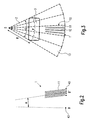
- Fig. 1 is a perspective view of a schematic represented in the however, especially a primary collimator and a Secondary collimator 1 omitted for clarity were.
- From an X-ray source O is by means of a Primary collimator (not shown) generates a fan beam 2.
- the slot-shaped primary collimator is made of a material the X-rays strongly absorbed, for example Copper or a lead compound.
- As the X-ray source becomes O an electron-beam radiation source in the high-power range (For example, 15 kW) and medium voltage (for example 180 kV).
- As a primary collimator is a Slit collimator uses only a thin Fan beam 2 on the luggage to be examined 3rd pass through. Both the X-ray source O and the Primary collimators are known in principle and not Essential to the invention, so that in more detail on their closer Design is not received.
- the through the Primary collimator transmitted fan beam 2 has a Opening angle ⁇ of 60 ° and a thickness in the Y direction of about 1 mm.
- the scattering point P is shown.
- the Z-axis is defined.
- the X-ray radiation transmitted along the Z-axis impinges on a detector 4 at the transmission point D.
- This transmission point D defines the origin of the Cartesian coordinate system X, Y, Z.
- the X-axis is defined so that it extends parallel to the plane in which the opening angle ⁇ of the fan beam 2 extends.
- On the perpendicular to the X-axis and Z-axis extending Y-axis hits a scattered beam to another detector element 40 of the detector 4.
- the coding of the scattering point P in the baggage item 3 to the specified scattered beam point D 'via the geometry of the Sekundärkollimators 1, what is described below to Figures 2 and 3.
- the detector 4 used is a Room temperature semiconductors, such as CdZnTe. Of the Detector 4 is here as a two-dimensional segmented Detector field formed. For clarity, only two rows of detector elements 40 are shown. A first Detector array 41 passes through the XZ plane Transmission point D. A second detector array 42 of Detector elements 40 passes through the scattered beam point D '. The first detector row 41 extends in the X direction from Starting point A to the end point B of the detector 4. This Both points are defined by the opening angle ⁇ of the Fan beam 2 set. The area of the scatter detector 4 is segmented in steps of about 1.5 mm in the Y direction and about 2 mm in the X direction. Every single one Detector element 40 is provided with a known analysis device connected. Such devices are known and not Essential to the invention, so that on the closer embodiment will not be discussed below.
- the size of the entire detector field is in its height in the X direction about 1755 mm and in its width in the Y direction about 27 mm.
- the scatter detector 4 points in the X direction 175 and in the Y direction 18 segments. It results Thus, a total of 3150 detector elements 40th With such a scatter detector 4, a piece of luggage 3 with Scanned a length of 1000 mm in the Y direction in 5 seconds are scanned at a data acquisition time of 5 ms per scan Millimeters, if the piece of luggage 3 along the Direction of movement 30 on a conveyor belt (not shown) is moved.
- the signal in a transmission detector 43 located at the Transmission point D is located, to check a Shielding in the area around the scattering point P in the luggage item 3 used.
- the obtained transmission signal can also be used can be used to the damping effects of the scattering data correct and a pre-scan fluoroscopic image of the To receive luggage 3.
- the secondary collimator is the first shown, which will be described in more detail below. He coded the angle at which the scattering point P, based on the Aperture angle ⁇ , is arranged on the X coordinate of the Detector field 40 and the distance R of the scattering point P of the X-ray source O on the Y-coordinate of the detector array 40. He only lets scattered radiation from one Narrow angle range around the scattering angle ⁇ around in the Detector 4 arrives. This is due to its geometry, like shown in Figures 2 and 3, achieved.
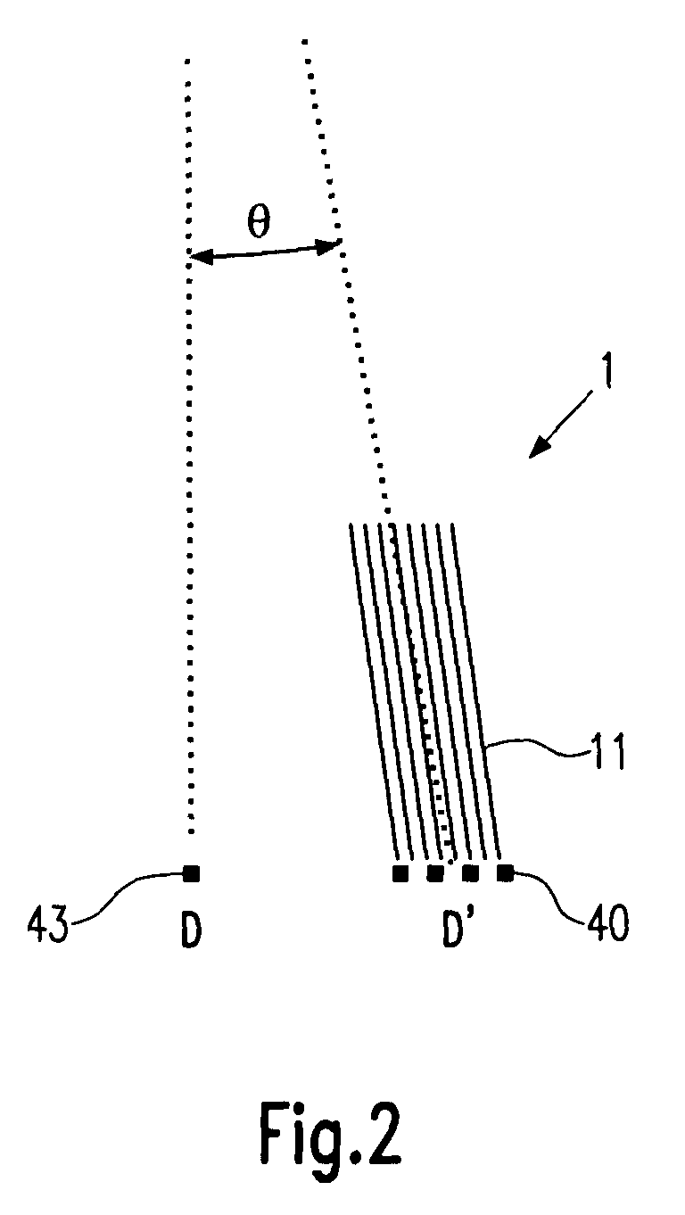
- FIG. 2 shows a section along the YZ plane through the secondary collimator 1.
- Vertical lamellae 11 can be seen which run parallel to one another. These vertical slats 11 are perpendicular to the YZ plane and are inclined by the scattering angle ⁇ against the Z-axis. They are made of an absorbent material, such as steel, and have a thickness of about 100 ⁇ m. Adjacent vertical fins 11 are spaced 1.5 mm apart, which corresponds to the width of a detector element 40 in the Y direction.
- FIG. 3 shows a section along the XZ plane.
- This plane contains the point at which the X-ray source O is arranged, as well as the starting point A and the end point B of the detector 4.
- Perpendicular to the plane shown run horizontal slats 12, which have a height (vertical to the plane shown) of 1.5 mm (as shown above for Fig. 2 described) and a width of about 2 mm Detector 4 (not shown), which is the width of a individual detector element 40 corresponds.
- the horizontal fins 12 are so aligned so that they all point to the X-ray source O.
- the columns are divided into a total of 5 modules 13 of the secondary collimator 1.
- Each module 13 is formed as a fan segment and has an opening angle of 12 °, so that results in a direct subsequent arrangement of the 5 modules 13 as the total opening angle, the 60 ° of the opening angle ⁇ of the fan beam 2.
- a module 13 has an extension of 27 mm in the Y direction and 350 mm at the detector in the X direction and 228 mm in the X direction directly below the conveyor belt (not shown) on which the item of luggage 3 to be checked.
- Each module 13 is combined to form a collimator unit 10 and arranged in a vertical steel container, so that with a precise joining of the modules 13 automatically results in an accuracy of 30 ⁇ m for the columns of the secondary collimator 1.
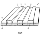
- first Metal sheet 15 is arranged on a sturdy and rigid base plate 14 .
- the first metal sheet 15 is by means of a known connection method, for example by gluing or spot welding firmly to the base plate 14 connected.
- the metal sheet 15 was previously by means of a preformed traditional metal processing.
- the metal sheet 15 has been shaped so that always alternately at 90 ° to each other vertical Slats 11 and horizontal slats 12 are formed. These are in each case via a straight folded edge 16 with each other connected. It is good to see that the vertical Slats 11 run in two mutually parallel planes, always alternately a vertical lamella 11 in the upper level and then lower level.
- the horizontal slats 12 do not run parallel to each other but converge on the X-ray source O. (Not shown).
- the preformed Sheet metal 15 by means of a template consisting of "forks" is formed, which are inserted into the columns 17, exactly fixed.
- an identically preformed Sheet metal 15 precisely above the last fastened Metal sheet 15 is arranged and by means of the above Template during joining exactly at this point held and by means of one of the aforementioned Connection method with the attached below Metal sheet 15 firmly connected.
- This method is repeated until all the metal sheets 15 are precisely stacked are.
- a piece of luggage 3 over analyzing the entire width of the fan beam 2 is it just as possible, only a module 13 in the Provide X-ray scattering device. Then only one Opening angle of 12 ° through the secondary collimator 1 and the Detector field 40 observed. This reduces the costs the X-ray diffraction device considerably, but at the price a lower test speed.
- the Device around the point, which through the X-ray source O is defined, either in the direction of the opening angle ⁇ be pivoted or perpendicular to this, to the missing Simulate sections of the primary fan beam 2.
- a Secondary collimator 1 of the invention Scattering point P on the X-coordinate of the detector array 40th is shown and the distance R of the scattering point P of the X-ray source O on the X-coordinate of the detector array 40th is shown.
- the secondary collimator 1 only a small angle range around the scattering angle ⁇ in the Detector 4 fall.
- a secondary collimator 1 according to the invention is at the same time mechanically extremely stable, which is too a high-precision XRD profile.
- the Secondary collimator 1 according to the invention very simple manufacture and of modular construction. It can thus by the choice of the number of modules used 13 an adaptation to the available financial resources, where the number of modules used 13 in direct Connection with the test speed of the item of baggage 3 stands.
Landscapes
- Physics & Mathematics (AREA)
- Spectroscopy & Molecular Physics (AREA)
- Engineering & Computer Science (AREA)
- General Engineering & Computer Science (AREA)
- High Energy & Nuclear Physics (AREA)
- Health & Medical Sciences (AREA)
- Life Sciences & Earth Sciences (AREA)
- Chemical & Material Sciences (AREA)
- Analytical Chemistry (AREA)
- Biochemistry (AREA)
- General Health & Medical Sciences (AREA)
- General Physics & Mathematics (AREA)
- Immunology (AREA)
- Pathology (AREA)
- Analysing Materials By The Use Of Radiation (AREA)
- Measurement Of Radiation (AREA)
Abstract
Description
- Fig. 1
- Eine schematische perspektivische Ansicht einer erfindungsgemäßen Röntgenstreuvorrichtung ohne Primärkollimator und Sekundärkollimator,
- Fig. 2
- einen Ausschnitt eines Schnitts durch die Röntgenstreuvorrichtung gemäß Fig. 1 in der YZ-Ebene mit Sekundärkollimator und einem Teil des Detektorfeldes,
- Fig. 3
- einen Ausschnitt eines Schnitts durch die Röntgenstrahlvorrichtung gemäß Fig.1 entlang der XZ-Ebene mit teilweise dargestelltem Streukollimator und
- Fig. 4
- eine schematische Darstellung eines teilweise zusammengesetzten Sekundäkollimators.
Auf der senkrecht zur X-Achse und Z-Achse verlaufenden Y-Achse trifft ein Streustrahl auf ein weiteres Detektorelement 40 des Detektors 4. Die Codierung des Streupunktes P im Gepäckstück 3 auf den angegebenen Streustrahlpunkt D' erfolgt über die Geometrie des Sekundärkollimators 1, was unten zu den Figuren 2 und 3 beschrieben wird.
- 1
- Sekundärkollimator
- 2
- Fächerstrahl
- 3
- Gepäckstück
- 4
- Detektor
- 10
- Kollimatoreinheit
- 11
- vertikale Lamelle
- 12
- horizontale Lamelle
- 13
- Modul
- 14
- Grundplatte
- 15
- Metallblech
- 16
- Falzkante
- 17
- Spalte
- 30
- Bewegungsrichtung
- 40
- Detektorelement
- 41
- erste Detektorreihe
- 42
- zweite Detektorreihe
- 43
- Transmissionsdetektor
- A,B
- Anfangs-, Endpunkt des Detektors
- D
- Transmissionspunkt
- D'
- Streustrahlpunkt
- O
- Röntgenquelle
- P
- Streupunkt
- Q
- Achse
- R
- Abstand
- α
- Öffnungswinkel
- Θ
- Streuwinkel
Claims (12)
- Sekundärkollimator (1) für eine Röntgenstreuvorrichtung mit horizontalen Lamellen (12) und senkrecht dazu angeordneten vertikalen Lamellen (11), wobei die vertikalen Lamellen (11) parallel zueinander angeordnet sind und um einen vorgebbaren Streuwinkel (Θ) zu einer Transmissionsrichtung eines Röntgenstrahls geneigt sind, und wobei die horizontalen Lamellen (12) fächerförmig auf einen einzigen Punkt, nämlich zur Röntgenquelle (O) hin, ausgerichtet sind, und die horizontalen Lamellen (12) mit den vertikalen Lamellen (11) ein rechteckiges Gitter bilden und in einer Kollimatoreinheit (10) zusammengefasst sind.
- Sekundärkollimator (1) nach Anspruch 1, dadurch gekennzeichnet, dass die Lamellen (11; 12) aus einem Röntgenstrahlen absorbierenden Material sind, insbesondere aus Stahl, und eine Dicke von unter 1 mm, insbesondere circa 100 µm, aufweisen.
- Sekundärkollimator (1) nach einem der Ansprüche 1 oder 2, dadurch gekennzeichnet, dass das rechteckige Gitter am Röntgenquellen-fernen Ende in horizontaler Richtung eine Breite von 1 - 10 mm und in vertikaler Richtung eine Höhe von 0,5 - 2,5 mm pro Gitterelement aufweist.
- Sekundärkollimator (1) nach einem der vorstehenden Ansprüche, dadurch gekennzeichnet, dass die Kollimatoreinheit (10) an ihrem Röntgenquellen-fernen Ende in Richtung der vertikalen Lamellen (11) eine Breite von insgesamt 350 mm und gleichzeitig an ihrem Röntgenquellen-nahen Ende in Richtung der vertikalen Lamellen (11) eine Breite von insgesamt 228 mm sowie zur Röntgenquelle (O) hin eine Höhe von insgesamt 250 mm aufweist und einen Öffnungswinkel (α) von 12° besitzt.
- Sekundärkollimator (1) nach einem der vorstehenden Ansprüche, ist dadurch gekennzeichnet, dass die Kollimatoreinheit (10) in einem lotrechten Stahlcontainer angeordnet ist.
- Sekundärkollimator (1) nach einem der vorstehenden Ansprüche, dadurch gekennzeichnet, dass fünf Kollimatoreinheiten (10) aneinandergefügt sind, die einen gesamten Öffnungswinkel (α) von 60° aufweisen.
- Sekundärkollimator (1) nach einem der vorstehenden Ansprüche, dadurch gekennzeichnet, dass auf einer robusten, steifen Grundplatte (14) eine Anzahl von Metallblechen (15) angeordnet ist, die gefaltete Flächen aufweisen, wobei jeweils aneinander angrenzende Flächen senkrecht aufeinander stehen und das erste Metallblech (15) mit der Grundplatte (14) fest verbunden ist sowie das zweite Metallblech (15) mit dem ersten Metallblech (15) fest verbunden ist und das jeweils nächste Metallblech (15) mit den vorhergehenden fest verbunden ist.
- Sekundärkollimator (1) nach Anspruch 7, dadurch gekennzeichnet, dass insgesamt 18 Metallbleche (15) auf der Grundplatte (14) angeordnet sind.
- Sekundärkollimator (1) nach Anspruch 7 oder 8, dadurch gekennzeichnet, dass an dem der Grundplatte (14) entgegengesetzten Ende das Metallblech (15) fest mit einer robusten, steifen Deckplatte verbunden ist.
- Röntgenstreuvorrichtung zur Gepäckkontrolle mit einer Röntgenquelle (O), mit einem Primärkollimator, der nur einen Fächerstrahl (2) durchlässt, mit einem Sekundärkollimator (1) zur Abbildung eines Bereichs eines Gepäckstücks (3) und mit einem Streudetektor (4), wobei der Sekundärkollimator (1) zwischen dem zu untersuchenden Gepäckstück (3) und dem Streudetektor (4) angeordnet ist und nach einem der vorstehenden Ansprüche ausgebildet ist.
- Röntgenstreuvorrichtung nach Anspruch 10, dadurch gekennzeichnet, dass zusätzlich ein Transmissionsdetektor (43) in gerader Verlängerung von der Röntgenquelle (O) über den zu untersuchenden Bereich des Gepäckstücks (3) angeordnet ist.
- Röntgenstreuvorrichtung nach einem der Ansprüche 10 oder 11, dadurch gekennzeichnet, dass der Sekundärkollimator (1) in vertikaler Richtung parallel zum Fächerstrahl (2) ausgerichtet ist und in horizontaler Richtung auf den zu untersuchenden Bereich des Gepäckstücks (3) ausgerichtet ist.
Applications Claiming Priority (2)
| Application Number | Priority Date | Filing Date | Title |
|---|---|---|---|
| DE102004014445A DE102004014445B4 (de) | 2004-03-24 | 2004-03-24 | Sekundärkollimator für eine Röntgenstreuvorrichtung sowie Röntgenstreuvorrichtung |
| DE102004014445 | 2004-03-24 |
Publications (3)
| Publication Number | Publication Date |
|---|---|
| EP1580765A2 true EP1580765A2 (de) | 2005-09-28 |
| EP1580765A3 EP1580765A3 (de) | 2006-08-16 |
| EP1580765B1 EP1580765B1 (de) | 2008-03-26 |
Family
ID=34854026
Family Applications (1)
| Application Number | Title | Priority Date | Filing Date |
|---|---|---|---|
| EP05006638A Ceased EP1580765B1 (de) | 2004-03-24 | 2005-03-24 | Sekundärkollimator für eine Röntgenstreuvorrichtung sowie Röntgenstreuvorrichtung |
Country Status (3)
| Country | Link |
|---|---|
| US (1) | US7463721B2 (de) |
| EP (1) | EP1580765B1 (de) |
| DE (1) | DE102004014445B4 (de) |
Cited By (1)
| Publication number | Priority date | Publication date | Assignee | Title |
|---|---|---|---|---|
| WO2010065460A3 (en) * | 2008-12-01 | 2010-08-19 | Morpho Detection, Inc. | Primary collimator and systems for x-ray diffraction imaging, and method for fabricating a primary collimator |
Families Citing this family (11)
| Publication number | Priority date | Publication date | Assignee | Title |
|---|---|---|---|---|
| US7359488B1 (en) * | 2004-05-25 | 2008-04-15 | Michel Sayag | Technique for digitally removing x-ray scatter in a radiograph |
| EP1896875A2 (de) * | 2005-06-14 | 2008-03-12 | L-3 Communications Security and Detection Systems, Inc. | Inspektionssystem mit materialidentifizierung |
| US7436932B2 (en) * | 2005-06-24 | 2008-10-14 | Varian Medical Systems Technologies, Inc. | X-ray radiation sources with low neutron emissions for radiation scanning |
| US7773724B2 (en) | 2006-07-11 | 2010-08-10 | Morpho Detection, Inc. | Systems and methods for generating an improved diffraction profile |
| US7881437B2 (en) * | 2006-07-11 | 2011-02-01 | Morpho Detection, Inc. | Systems and methods for developing a primary collimator |
| US7889845B2 (en) * | 2007-12-20 | 2011-02-15 | Morpho Detection, Inc. | Secondary collimator and method of assembling the same |
| US7835495B2 (en) * | 2008-10-31 | 2010-11-16 | Morpho Detection, Inc. | System and method for X-ray diffraction imaging |
| US20110188632A1 (en) * | 2010-02-03 | 2011-08-04 | Geoffrey Harding | Multiple plane multi-inverse fan-beam detection systems and method for using the same |
| US8223925B2 (en) | 2010-04-15 | 2012-07-17 | Bruker Axs Handheld, Inc. | Compact collimating device |
| EP3933881A1 (de) | 2020-06-30 | 2022-01-05 | VEC Imaging GmbH & Co. KG | Röntgenquelle mit mehreren gittern |
| US12230468B2 (en) | 2022-06-30 | 2025-02-18 | Varex Imaging Corporation | X-ray system with field emitters and arc protection |
Family Cites Families (18)
| Publication number | Priority date | Publication date | Assignee | Title |
|---|---|---|---|---|
| US4057726A (en) * | 1975-12-22 | 1977-11-08 | G. D. Searle & Co. | Collimator trans-axial tomographic scintillation camera |
| JPS5940284A (ja) * | 1982-08-31 | 1984-03-05 | Shimadzu Corp | 放射線結像装置用コリメ−タ |
| DE3886334D1 (de) * | 1987-10-05 | 1994-01-27 | Philips Patentverwaltung | Anordnung zur Untersuchung eines Körpers mit einer Strahlenquelle. |
| JPH03120500A (ja) * | 1989-10-04 | 1991-05-22 | Toshiba Corp | 多孔コリメータ及びその製造方法 |
| EP0412190B1 (de) * | 1989-08-09 | 1993-10-27 | Heimann Systems GmbH & Co. KG | Vorrichtung zum Durchstrahlen von Gegenständen mittels fächerförmiger Strahlung |
| US5231655A (en) * | 1991-12-06 | 1993-07-27 | General Electric Company | X-ray collimator |
| DE59308726D1 (de) * | 1992-02-06 | 1998-08-13 | Philips Patentverwaltung | Anordnung zum Messen des Impulsübertragsspektrums von elastisch gestreuten Röntgenquanten |
| GB2297835A (en) * | 1995-02-08 | 1996-08-14 | Secr Defence | Three dimensional detection of contraband using x rays |
| DE19510168C2 (de) * | 1995-03-21 | 2001-09-13 | Heimann Systems Gmbh & Co | Verfahren und Vorrichtung zur Bestimmung von kristallinen und polykristallinen Materialien in einem Untersuchungsbereich |
| US5949850A (en) * | 1997-06-19 | 1999-09-07 | Creatv Microtech, Inc. | Method and apparatus for making large area two-dimensional grids |
| WO1999039189A2 (en) * | 1998-01-28 | 1999-08-05 | American Science And Engineering, Inc. | Gated transmission and scatter detection for x-ray imaging |
| EP0984302B1 (de) * | 1998-09-04 | 2003-08-20 | YXLON International X-Ray GmbH | Verfahren und Vorrichtung zur Prüfung von Reisegepäck durch Röngtendurchleuchtung |
| EP1192479B1 (de) * | 1999-03-15 | 2013-05-29 | Philips Digital Mammography Sweden AB | Gerät und verfahren zur röntgenstrahlungsabbildung |
| US6470072B1 (en) * | 2000-08-24 | 2002-10-22 | General Electric Company | X-ray anti-scatter grid |
| US6987836B2 (en) * | 2001-02-01 | 2006-01-17 | Creatv Microtech, Inc. | Anti-scatter grids and collimator designs, and their motion, fabrication and assembly |
| DE10136946A1 (de) * | 2001-07-28 | 2003-02-06 | Philips Corp Intellectual Pty | Streustrahlenraster für eine Röntgeneinrichtung |
| DE50200624D1 (de) * | 2002-02-26 | 2004-08-19 | Yxlon Int Security Gmbh | Simultan-Multifokus kohärente Röntgenstreuung (CXRS) |
| DE10241423B4 (de) * | 2002-09-06 | 2007-08-09 | Siemens Ag | Verfahren zur Herstellung und Aufbringung eines Streustrahlenrasters oder Kollimators auf einen Röntgen- oder Gammadetektor |
-
2004
- 2004-03-24 DE DE102004014445A patent/DE102004014445B4/de not_active Expired - Fee Related
-
2005
- 2005-03-24 US US11/090,445 patent/US7463721B2/en not_active Expired - Fee Related
- 2005-03-24 EP EP05006638A patent/EP1580765B1/de not_active Ceased
Cited By (1)
| Publication number | Priority date | Publication date | Assignee | Title |
|---|---|---|---|---|
| WO2010065460A3 (en) * | 2008-12-01 | 2010-08-19 | Morpho Detection, Inc. | Primary collimator and systems for x-ray diffraction imaging, and method for fabricating a primary collimator |
Also Published As
| Publication number | Publication date |
|---|---|
| US7463721B2 (en) | 2008-12-09 |
| US20050281383A1 (en) | 2005-12-22 |
| EP1580765B1 (de) | 2008-03-26 |
| DE102004014445A1 (de) | 2005-10-13 |
| DE102004014445B4 (de) | 2006-05-18 |
| EP1580765A3 (de) | 2006-08-16 |
Similar Documents
| Publication | Publication Date | Title |
|---|---|---|
| EP1241470B1 (de) | Anordnung zum Messen des Impulsübertragungsspektrums von in einem Untersuchungsbereich für Behältnisse elastisch gestreuten Röntgenquanten | |
| DE4216929C2 (de) | Einrichtung zur Abbildung eines Gegenstandes mittels gestreuter Strahlung | |
| EP1107260B1 (de) | Gitter zur Absorption von Röntgenstrahlen | |
| EP0714037B1 (de) | Anordnung zum Messen des Impulsübertragsspektrums von elastisch gestreuten Röntgenquanten | |
| DE102010047205B4 (de) | Sekundärkollimator und Verfahren desselben | |
| DE3689231T2 (de) | Röntgenstrahlquelle. | |
| DE10303438A1 (de) | Röntgenfluoreszenzspektrometer für Halbleiter | |
| EP1580765B1 (de) | Sekundärkollimator für eine Röntgenstreuvorrichtung sowie Röntgenstreuvorrichtung | |
| DE102006023309A1 (de) | Verfahren und Vorrichtung zur Erkennung von Material mittels Schnellneutronen und eines kontinuierlichen spektralen Röntgenstrahles | |
| EP3004851A1 (de) | Verfahren zur bestimmung der brechkraft eines transparenten objekts sowie entsprechende vorrichtung | |
| EP1754969B1 (de) | Computertomograph und Verfahren zur Untersuchung unterschiedlich großer Objekte | |
| DE102012220235A1 (de) | Röntgenstrahlintensitätskorrekturverfahren und Röntgenstrahldiffrektometer | |
| DE3705423A1 (de) | Verfahren zum ausrichten eines roentgenstrahlendetektors mit einem linearen feld | |
| EP3761015B1 (de) | Prüfkörper | |
| DE102005009817B4 (de) | Lochmaske für einen Röntgenstrahlendetektor, Computertomographiegerät, aufweisend eine Lochmaske und Verfahren zur Justierung einer Lochmaske | |
| DE10164245A1 (de) | Verfahren zum Kompensieren eines Spaltes bei volumetrischen Mehrfachplatten-CT-Abtastern und zugehörige Vorrichtung | |
| DE10125454A1 (de) | Gerät zur Röntgenanalyse mit einem Mehrschichtspiegel und einem Ausgangskollimator | |
| DE10221200B4 (de) | Röntgenfluoreszenzspektrometer | |
| DE102005011467B4 (de) | Kollimator mit einstellbarer Brennweite, hierauf gerichtetes Verfahren sowie Röntgenprüfanlage | |
| DE202025103491U1 (de) | Flächendichte-Vollkontrollgerät | |
| EP3928085A1 (de) | Messanordnung für röntgenstrahlung für eine spaltfreie 1d-messung | |
| DE102004060612B4 (de) | Anordnung zum Messen des Impulsübertragungsspektrums von elastisch gestreuten Röntgenquanten | |
| DE3140714A1 (de) | Vorrichtung zur dickenmessung von flachprofilen | |
| EP1100092A2 (de) | Vorrichtung zur Führung von Röntgenstrahlen | |
| DE102004060608B4 (de) | Verfahren zur Korrektur der Schwächung der Compton-Streuquanten |
Legal Events
| Date | Code | Title | Description |
|---|---|---|---|
| PUAI | Public reference made under article 153(3) epc to a published international application that has entered the european phase |
Free format text: ORIGINAL CODE: 0009012 |
|
| AK | Designated contracting states |
Kind code of ref document: A2 Designated state(s): AT BE BG CH CY CZ DE DK EE ES FI FR GB GR HU IE IS IT LI LT LU MC NL PL PT RO SE SI SK TR |
|
| AX | Request for extension of the european patent |
Extension state: AL BA HR LV MK YU |
|
| PUAL | Search report despatched |
Free format text: ORIGINAL CODE: 0009013 |
|
| AK | Designated contracting states |
Kind code of ref document: A3 Designated state(s): AT BE BG CH CY CZ DE DK EE ES FI FR GB GR HU IE IS IT LI LT LU MC NL PL PT RO SE SI SK TR |
|
| AX | Request for extension of the european patent |
Extension state: AL BA HR LV MK YU |
|
| RIC1 | Information provided on ipc code assigned before grant |
Ipc: G01N 23/201 20060101ALI20060712BHEP Ipc: G21K 1/02 20060101AFI20050705BHEP Ipc: G01V 5/00 20060101ALI20060712BHEP |
|
| 17P | Request for examination filed |
Effective date: 20070216 |
|
| 17Q | First examination report despatched |
Effective date: 20070320 |
|
| AKX | Designation fees paid |
Designated state(s): GB |
|
| REG | Reference to a national code |
Ref country code: DE Ref legal event code: 8566 |
|
| RAP1 | Party data changed (applicant data changed or rights of an application transferred) |
Owner name: GE HOMELAND PROTECTION, INC. |
|
| GRAP | Despatch of communication of intention to grant a patent |
Free format text: ORIGINAL CODE: EPIDOSNIGR1 |
|
| GRAS | Grant fee paid |
Free format text: ORIGINAL CODE: EPIDOSNIGR3 |
|
| GRAA | (expected) grant |
Free format text: ORIGINAL CODE: 0009210 |
|
| AK | Designated contracting states |
Kind code of ref document: B1 Designated state(s): GB |
|
| REG | Reference to a national code |
Ref country code: GB Ref legal event code: FG4D Free format text: NOT ENGLISH |
|
| PLBE | No opposition filed within time limit |
Free format text: ORIGINAL CODE: 0009261 |
|
| STAA | Information on the status of an ep patent application or granted ep patent |
Free format text: STATUS: NO OPPOSITION FILED WITHIN TIME LIMIT |
|
| 26N | No opposition filed |
Effective date: 20081230 |
|
| PGFP | Annual fee paid to national office [announced via postgrant information from national office to epo] |
Ref country code: GB Payment date: 20100625 Year of fee payment: 6 |
|
| GBPC | Gb: european patent ceased through non-payment of renewal fee |
Effective date: 20110324 |
|
| PG25 | Lapsed in a contracting state [announced via postgrant information from national office to epo] |
Ref country code: GB Free format text: LAPSE BECAUSE OF NON-PAYMENT OF DUE FEES Effective date: 20110324 |
|
| P01 | Opt-out of the competence of the unified patent court (upc) registered |
Effective date: 20230528 |