EP1580439A2 - Fluidtechnischer Betätigungshebel - Google Patents
Fluidtechnischer Betätigungshebel Download PDFInfo
- Publication number
- EP1580439A2 EP1580439A2 EP05102309A EP05102309A EP1580439A2 EP 1580439 A2 EP1580439 A2 EP 1580439A2 EP 05102309 A EP05102309 A EP 05102309A EP 05102309 A EP05102309 A EP 05102309A EP 1580439 A2 EP1580439 A2 EP 1580439A2
- Authority
- EP
- European Patent Office
- Prior art keywords
- push rod
- rod assembly
- supporting body
- control element
- flow control
- Prior art date
- Legal status (The legal status is an assumption and is not a legal conclusion. Google has not performed a legal analysis and makes no representation as to the accuracy of the status listed.)
- Withdrawn
Links
Images


Classifications
-
- F—MECHANICAL ENGINEERING; LIGHTING; HEATING; WEAPONS; BLASTING
- F15—FLUID-PRESSURE ACTUATORS; HYDRAULICS OR PNEUMATICS IN GENERAL
- F15B—SYSTEMS ACTING BY MEANS OF FLUIDS IN GENERAL; FLUID-PRESSURE ACTUATORS, e.g. SERVOMOTORS; DETAILS OF FLUID-PRESSURE SYSTEMS, NOT OTHERWISE PROVIDED FOR
- F15B13/00—Details of servomotor systems ; Valves for servomotor systems
- F15B13/02—Fluid distribution or supply devices characterised by their adaptation to the control of servomotors
- F15B13/04—Fluid distribution or supply devices characterised by their adaptation to the control of servomotors for use with a single servomotor
- F15B13/042—Fluid distribution or supply devices characterised by their adaptation to the control of servomotors for use with a single servomotor operated by fluid pressure
- F15B13/0422—Fluid distribution or supply devices characterised by their adaptation to the control of servomotors for use with a single servomotor operated by fluid pressure with manually-operated pilot valves, e.g. joysticks
Definitions
- the present invention relates to a fluid-operated actuation device.
- Fluid-operated actuation devices known as remote controls, are known which allow to drive, optionally remotely, distribution valves, hydraulic pumps, hydrostatic drives and others.
- These devices comprise a supporting body, which is provided with at least one through receptacle connected to means for feeding a pressurized working fluid, preferably oil.
- Such receptacle is provided with a first end and a second end, which are mutually opposite and proximate to which there are respectively a first section, which acts as a guide for the sliding of a push rod that is arranged inside it and protrudes partially from the first end, and a second section, which is connected to said feeder means and acts as a valve body for a flow control element that cooperates with the push rod in order to reduce the pressure of the fluid in output from the second end of said receptacle.
- the device is provided with first elastic means, which are interposed between the body and the push rod for the return of the push rod to the inactive configuration, with second elastic means, which are interposed between the push rod and the flow control element and are sized so as to modulate the reduction in pressure between the intake and the output from the device, with third elastic means, which are interposed between the flow control element and the body for the return of the element to the inactive configuration, and with sealing means, which are accommodated within the receptacle in order to prevent the outflow of fluid through the first end.
- These means are constituted by loose components, such as elastic compression springs and sealing rings, which must be assembled individually during the manufacture of said devices.
- the type of response given by the device according to the actuation imparted by the user depends on the size of the second elastic means.
- the device further comprises means for actuating the sliding of the push rod along the receptacle, which are associated with the supporting body and can be actuated by an operator.
- the actuation means generally comprise an actuation element, such as a lever or pedal, which is hinged to the valve body and is rigidly coupled to a rocker associated with at least one protruding tab, which is formed for example by the head of a screw that is engaged in the rocker and is suitable to press on the push rod as a consequence of the rotation of the element produced by the operator.
- an actuation element such as a lever or pedal
- Actuation devices are also known in which the body is provided with at least two receptacles that are associated with respective push rods and respective flow control elements, in which the rocker is associated with two tabs, each of which cooperates with a respective push rod.
- the receptacles are arranged along an axis that passes through the region where the actuation element is hinged to the body and are arranged on opposite sides of the region.
- These devices are conventionally termed single-axis two-way devices and can be arranged in a pack by interposing suitable interfaces so as to form modular assemblies for example for actuating a plurality of distribution valves.
- so-called two-axis four-way actuation assemblies are known in which there are four receptacles distributed around the region where the actuation element is hinged to the body and arranged along two axes, which are mutually perpendicular and intersect at said region.
- the receptacles arranged along a same axis are coupled to a same user device.
- the rocker can be replaced by a plate, which supports four tabs, each of which cooperates with a corresponding push rod.
- This fact entails, in order to minimize the resources held in store, the need to keep in store the various loose components which, when a customer order is received, must be individually assembled on a workbench in order to obtain the devices, which must then be tested before shipping.
- the aim of the present invention is to eliminate the above-mentioned drawbacks of known devices, by providing a fluid-operated actuation device that allows to optimize the flexibility of the corresponding production cycle according to the variation of the adjustment curve of the reduced pressure in output.
- an object of the present invention is to facilitate assembly operations, minimizing the associated times and costs.
- Another object of the present invention is to ensure a response of the device that is uniform and progressive in accordance with the actuation imparted by users.
- Another object of the present invention is to obtain a device whose actuation on the part of users does not cause fatigue and is not onerous.
- Another object of the present invention is to provide a device that is simple, relatively easy to provide in practice, safe in use, effective in operation, and has a relatively low cost.
- the present fluid-operated actuation device characterized in that it comprises at least one supporting body, which is associated with at least one substantially through receptacle provided with first and second mutually opposite open ends, at least one preassembled push rod assembly, which is inserted so that it can slide along said receptacle at said first end, means for actuating the sliding of said push rod assembly along said receptacle at least toward said second end, and at least one preassembled reduction valve assembly, which is associated with said supporting body at said second end and comprises a valve body provided with at least one intake port for a working fluid at an operating pressure, with at least one port for the output of the working fluid at a reduced pressure toward a user device, and with at least one discharge port for said fluid and at least one flow control element, which is accommodated within said valve body, can move alternately between an inactive configuration and an active configuration, is interposed between said ports and cooperates with said push rod assembly, said flow control element being adapted to
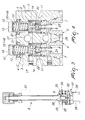
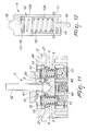
- the reference numeral 1 generally designates a fluid-operated actuation device.
- the device 1 comprises at least one supporting body 2, which is associated with at least one through receptacle 3 provided with a first end and a second end, which are open and mutually opposite and are arranged respectively in an upper region and in a lower region with reference to to the figures.
- the receptacle 3 is formed by a through hole provided in the supporting body 2.
- the device 1 further comprises at least one preassembled push rod assembly 4, which is inserted so that it can slide within the receptacle 3 proximate to its first end, and means 5 for actuating the sliding of the push rod assembly 4 along the receptacle 3 at least toward its second end.
- the push rod assembly 4 preferably protrudes partially from the first end of the receptacle 3 toward the actuation means 5.
- the device 1 further comprises at least one preassembled reduction valve assembly 6, which is associated with the supporting body 2 at the second end of the receptacle 3 and comprises a valve body 7, which is provided with at least one intake port 7a for a working fluid at an operating pressure, at least one output or service port 7b for the output of the working fluid at a reduced pressure toward a user, and with at least one discharge port 7c for discharging said fluid and at least one flow control element 8, which is accommodated within the valve body 7 and can move alternately between an inactive configuration and an active configuration, is interposed between the ports 7a, 7b and 7c, and cooperates with the push rod assembly 4.
- a preassembled reduction valve assembly 6 which is associated with the supporting body 2 at the second end of the receptacle 3 and comprises a valve body 7, which is provided with at least one intake port 7a for a working fluid at an operating pressure, at least one output or service port 7b for the output of the working fluid at a reduced pressure toward a user, and with at least one discharge port 7c
- the flow control element 8 is arranged in such a position as to close the intake port 7a and connect the output and discharge ports 7b and 7c respectively.
- actuation means 5 it is possible to actuate the sliding of the flow control element 8 so as to move it into the active configuration in order to close at least partially the discharge port 7c and connect the intake and output ports 7a and 7b respectively.
- the flow control element 8 is constituted by an elongated element, which is arranged so that a first end lies within the valve body 7 at the output port 7b and a second end, arranged opposite the first end, protrudes outward from the valve body and is associated with the push rod assembly 4.
- the flow control element 8 is provided internally with a cavity that is open at the first end and with two through holes that lie transversely to the cavity: one of the holes, in the inactive configuration, is arranged at the discharge port 7c so as to connect it to the output port 7b in order to evacuate the working fluid, and the other hole, in the active configuration, is arranged at the intake port 7a in order to feed the working fluid toward the user device.
- the working fluid is preferably hydraulic oil or the like.
- the push rod assembly 4 and the valve assembly 6 are constituted by corresponding preassembled and preferably tested cartridges fitted to the supporting body 2.
- the actuation means 5 comprise a cam 9, which is movably associated with the supporting body 2, and means 10 for pivoting about at least one axis, which are interposed between the supporting body and the cam 9.
- the use of the cam 9 allows to obtain a response of the device 1 to the action applied by the user to the actuation means 5 that is highly regular and progressive; moreover, by varying the profile of the cam 9 it is possible to achieve different response curves of the device 1.
- the device 1 comprises first elastic means for the retraction of the push rod assembly 4 away from the second end of the receptacle 3, which are constituted by at least one first helical compression spring 11, which is interposed between the assembly and the valve body 7; as an alternative, the first spring 11 can be interposed between the push rod assembly 4 and the supporting body 2.
- the push rod assembly 4 is constituted by a cartridge that can be yield elastically by way of the action imparted by the actuation means 5.
- the push rod assembly 4 comprises a box-like enclosure 12, which is formed by at least one first portion 12a, which cooperates with the actuation means 5, and by a second portion 12b, which is associated with the flow control element 8; such portions are mutually associated so that they can move toward and away from each other by way of the interposition of second elastic means, which are constituted by at least one second helical compression spring 13.
- the second elastic means may provide two second coaxial springs 13, which mutually cooperate so as to obtain a reduced pressure response curve, according to the movement imparted to the actuation means 5, that is characterized by a double gradient.
- the portions 12a and 12b are substantially cup-shaped and arranged so that their corresponding bottom walls face opposite directions; the second portion 12b is arranged inside the first portion 12a.
- the push rod assembly 4 comprises first stroke limiting means for limiting the relative sliding of the portions 12a and 12b away from each other; such means are constituted for example by an elastic ring 14, which is accommodated so as to protrude from an annular seat formed on the internal wall of the first portion 12a proximate to its open end that is arranged in a lower region with respect to the drawings, so as to form an abutment shoulder for the second portion 12b.
- the ring 14 allows to make the preassembly of the push rod assembly 4 stable.
- the push rod assembly 4 may have second stroke limiting means for limiting the sliding of the portions 12a and 12b toward each other, which are constituted by an insert 15, which is accommodated within the first portion 12a at its bottom, which forms an annular surface for abutment of the second portion 12b.
- the insert 15 is sized so as to limit the useful stroke of the portions 12a and 12b with respect to each other and therefore limit the deflection of the second spring 13 so that it is packed.
- the insert 15 allows to convert the connection between the portions 12a and 12b from an elastic one to a rigid one for a given movement imparted by the user by way of the actuation means 5, so as to achieve a sudden increase in the reduced pressure to a maximum value that is equal to approximately 80% of the input operating pressure.
- the push rod assembly 4 further has third means for limiting the stroke of its sliding motion along the receptacle 3 at least toward its first end, such means being constituted for example by a second elastic ring 17, which is accommodated so as to protrude in an annular seat formed on the outer wall of the first portion 12a proximate to its closed end arranged in an upper region with respect to the drawings, so as to form a surface for abutment on a shoulder formed inside the supporting body 2.
- third means for limiting the stroke of its sliding motion along the receptacle 3 at least toward its first end such means being constituted for example by a second elastic ring 17, which is accommodated so as to protrude in an annular seat formed on the outer wall of the first portion 12a proximate to its closed end arranged in an upper region with respect to the drawings, so as to form a surface for abutment on a shoulder formed inside the supporting body 2.
- the first portion 12a which acts as a transfer element, is provided in an upper region with a surface 18, which is arranged in contact with the cam 9 and can be flat ( Figures 5 and 6) or convex ( Figure 12).
- the second portion 12b is provided with a protruding tang 19, which enters a corresponding recess 20 provided on the second end of the flow control element 8.
- first sealing means are interposed between the supporting body 2 and the first portion 12a and are constituted by a gasket 21, which is accommodated in a corresponding annular slot provided at the first end of the receptacle 3.
- the valve assembly 6 comprises fourth means for limiting the stroke of the sliding motion of the flow control element 8 along the valve body 7.
- the fourth stroke limiting means comprise a perimetric flange 22, which protrudes outward from the second end of the flow control element 8 and is suitable to abut against the valve body in order to limit the sliding of the flow control element 8 away from the push rod assembly 4.
- the flange 22 is applied to the flow control element 8; in an alternative embodiment, not shown, the flange 22 can be formed for example monolithically with the flow control element 8.
- the fourth stroke limiting means comprise a third ring 23, which is accommodated so as to protrude from an annular seat that is formed on the outer wall of the flow control element 8 at its first end and is suitable to abut against a shoulder formed inside the valve body 7, in order to limit the sliding of the flow control element 8 toward the push rod assembly 4 and allow the preassembly of the valve assembly 6 to be stable.
- the valve body 6 further comprises third elastic means for the return of the flow control element 8 to the inactive configuration upon release of the actuation means 5 by a user, said third means being constituted by at least one third helical compression spring 24, which is interposed between the valve body 7 and the flow control element 8.
- the third spring 24 wraps around the second end of the flow control element 8 and is interposed between the flange 22 that is associated with it and the valve body 7.
- the valve body 6 further comprises second sealing means, which comprise one or more sealing rings 25 which are interposed between the valve body 7 and the supporting body 2 and are accommodated in corresponding seats provided on said valve body.
- valve assembly 6 can be inserted in the receptacle 3 at its second end.
- the intake port 7a is connected to a supply circuit 26, which is formed inside the supporting body 2 and is connected to the outside for coupling with means for supplying the working fluid at the operating pressure, which are not shown because they are of a conventional type.
- the discharge port 7c is connected to a discharge circuit 27, which is formed inside the supporting body 2 and is connected to the outside for coupling to means for collecting the working fluid, which are not shown and are constituted for example by a conventional tank.
- valve assembly 6 can be associated with the supporting body 2 by way of connection means, preferably of the detachable type, such as threaded elements 28 or the like.
- the intake port 7a and the discharge port 7c are connected to the outside of the valve body 7 by way of respective ducts 29 and 30, which are formed in the valve body, for coupling respectively to the supply means and to the collection means.
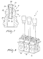
- the actuation means 5 comprise a control element 31 for the movement of the cam 9, such as a lever, a pedal or the like.
- the control element 31 can be provided with means for locking in the inactive configuration or with electric or electronic controls.
- the device 1 comprises a single receptacle 3, in which there is a push rod assembly 4, which cooperates with a corresponding valve assembly 6 inserted in the supporting body 2 or associated therewith; in this case, the control element 31 is of the pedal type.
- the device 1 is of the single-axis two-way type.
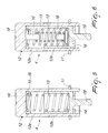
- the supporting body 2 is provided with two receptacles 3, in which respective push rod assemblies 4 are arranged; each assembly cooperates with a corresponding valve assembly 6, which is inserted in said receptacle at the second end.
- valve assembly 6 which is associated with the supporting body 2 at the second ends of the receptacles 3 and the valve body 7 of which is provided with: two intake ports 7a, which are mutually connected and associated with means for supplying the working fluid at the operating pressure by means of the duct 29; two output ports 7b and two discharge ports 7c, which are mutually connected and are associated with means for collecting said fluid through the duct 30; and two flow control elements 8, which are accommodated so that they can move along the valve body 7, each element being interposed between a respective intake port 7a and the corresponding output and discharge ports 7b and 7c respectively, and cooperates with one of the two push rod assemblies 4.
- the pivoting means 10 comprise an articulation pivot 32, which is inserted in the cam 9 and defines the rotation axis of said cam.
- the receptacles 3 are arranged along an axis that is perpendicular to the articulation pivot 32 and on opposite sides thereof.
- the cam 9 is of the flat type and lies on a plane that is perpendicular to the articulation pivot 32.
- the pivoting means 10 comprise one or, more preferably, two wings 33 for supporting the articulation pivot 32, which are arranged at the mutually opposite ends of said pivot and are associated with the supporting body 2 at the first ends of the receptacles 3, for example by way of threaded elements 34.
- the pivoting means 10 further have a preassembled friction assembly 35, which is associated with each wing 33; said assemblies are not described in detail since they are of a conventional type.
- a plate 36 for fitting the device 1 on control panels or other elements is interposed between the wings 33 and the supporting body 2.
- valve assemblies 6 are kept in position within the corresponding receptacles 3 by means of a contrast plate 37, which is fixed to the supporting body 2, for example, by means of threaded elements or other connecting elements, which are not shown.
- valve bodies 7 might be threaded externally and be screwed into corresponding female threads formed along the receptacles 3 with the interposition of a safety ring.
- a threaded stem 38 is partially inserted in the cam 9 for connection to the control element 31.
- Figure 3 illustrates a control element 31, such as a lever, which is not described in detail since it is of a conventional type.
- the actuation means 5 can be preassembled, so as to form a compact subassembly to be fitted to the supporting body 2.
- Figure 8 illustrates a second embodiment, in which a plurality of sections having a single axis and two ways of the type described above, designated respectively by the reference numerals 1a, 1b and 1c, are packed by interposing respective interfaces of a known type so as to form an actuation device with three parallel axes and six ways; each section 1a, 1b, 1c of the the device 1 is coupled, during use, to a corresponding fluid-operated component to be driven.
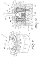
- the device 1 is of the type with two axes and four ways.
- the supporting body 2 is provided with four receptacles 3, in which there are respective push rod assemblies 4, which cooperate with a single valve assembly 6 that is associated with the supporting body 2 at the second ends of the receptacles 3.
- the valve assembly 6 comprises a valve body 7, which is provided with four mutually connected intake ports 7a, which are associated with means for supplying the working fluid at the operating pressure through the duct 29, with four output ports 7b, and with four discharge ports 7c, which are mutually connected and are associated with means for collecting said fluid by means of the duct 30, and four flow control elements 8, which are accommodated so that they can move within the valve body 7, each one being interposed between a respective intake port 7a and the corresponding output and discharge ports 7b and 7c respectively, and cooperates with one of the two push rod assemblies 4.
- valve assemblies 6 each inserted into a corresponding receptacle 3 at its second end and cooperating with a corresponding push rod assembly 4.
- valve body 7 of each valve assembly 6 is provided with an intake port 7a, which is connected to the supply circuit 26 formed in the supporting body 2, with an output port 7b, and with a discharge port 7c, which is connected to the discharge circuit 27 formed in said supporting body.
- the pivoting means 10 comprise a ball joint 39, which is interposed between the supporting body 2 and the cam 9.
- the receptacles 3 are distributed around the ball joint 39 along two mutually perpendicular axes, which pass through said joint and are arranged in pairs on opposite sides thereof.
- the cam 9 is of the front type and is constituted by a disk that has an appropriately contoured surface that faces the push rod assemblies 4.
- the two receptacles 3 arranged on a same axes are coupled to a same fluid-operated component to be driven.
- Moving the control element 31 along one of said axes actuates one of the push rod assemblies 4 and accordingly the corresponding valve assembly 6; by moving the control element 31 transversely to said axes it is instead possible to act simultaneously on two adjacent push rod assemblies 4 and on the corresponding valve assemblies 6.
- the ball joint 39 can be provided with guiding means, which are suitable to allow the rotation of said joint only in directions that are parallel to said axes, so as to prevent "diagonal" actuation or limit the movement along one axis or a so-called half axis.
- Such guiding means can be constituted for example by a plate provided with an appropriately cross-shaped or T-shaped slot, along which the actuation element 31 moves.
- the ball joint 39 is composed of a female element, which is constituted by a recess 40 provided in the upper wall of the supporting body 2, between the receptacles 3, and a male element, which is constituted by a essentially spherical head 41, which is inserted in the recess 40 and is rigidly coupled to a threaded stem 42 for fitting the control element 31, which is not shown and is generally constituted by a lever.
- the cam 9 is screwed onto the stem 42; it is possible to provide a safety nut in order to keep the cam 9 in position on said stem.
- the pivoting means 10 comprise means for locking the rotation of the control element 31 about an axis that is parallel to the sliding direction of the push rod assemblies 4, so as to facilitate the fitting of said element to the stem 42.
- the locking means comprise a first substantially diametrical notch 43, which is formed on the head 41 on a plane that passes through said axis, a corresponding second notch, which is formed in the supporting body 2 and faces the recess 40, and a pin, which is interposed between the first notch and the second notch, said pin and the second notch not being shown in the figures.
- the surface of the plate 44 that faces it is spherical, so as to allow the rotation of the head 41 with respect to said plate.
- the cam 9 By acting on the control element 31, the cam 9 is turned and acts on at least one push rod assembly 4, the enclosure 12 of which moves toward the corresponding valve assembly 6.
- the second spring 13 is compressed and pushes the flow control element 8, which causes the total or partial closure of the corresponding discharge port 7c and connects the intake and output ports 7a and 7b respectively.
- the flow control element 8 is arranged in equilibrium between the elastic force applied by the springs 11, 13 and 24 and the pushing force applied by the fluid at the working pressure at the intake port 7a and at the reduced pressure at the output port 7b.
- the value of the reduced pressure is a function of the movement imparted to the control element 31, of the profile of the cam 9 that is used, and of the yielding of the push rod assembly 4.
- the device 1 is characterized by considerable comfort in use on the part of users; use of the cam 9, combined with the reduced diameter of the flow control elements 8, in fact causes a very limited reaction on the hand or feet of the users who drive said device by means of the control element 31.
- the push rod assembly or assemblies 4 are inserted in the corresponding receptacles 3 in an upward direction from below.
- valve assemblies 6 are inserted in corresponding receptacles 3, these too are inserted in an upward direction from below.
Landscapes
- Engineering & Computer Science (AREA)
- Physics & Mathematics (AREA)
- Fluid Mechanics (AREA)
- Mechanical Engineering (AREA)
- General Engineering & Computer Science (AREA)
- Mechanically-Actuated Valves (AREA)
Applications Claiming Priority (2)
| Application Number | Priority Date | Filing Date | Title |
|---|---|---|---|
| ITMO20040064 | 2004-03-26 | ||
| ITMO20040064 ITMO20040064A1 (it) | 2004-03-26 | 2004-03-26 | Dispositivo di comando a mezzo fluido |
Publications (2)
| Publication Number | Publication Date |
|---|---|
| EP1580439A2 true EP1580439A2 (de) | 2005-09-28 |
| EP1580439A3 EP1580439A3 (de) | 2007-05-09 |
Family
ID=34856945
Family Applications (1)
| Application Number | Title | Priority Date | Filing Date |
|---|---|---|---|
| EP05102309A Withdrawn EP1580439A3 (de) | 2004-03-26 | 2005-03-22 | Fluidtechnischer Betätigungshebel |
Country Status (2)
| Country | Link |
|---|---|
| EP (1) | EP1580439A3 (de) |
| IT (1) | ITMO20040064A1 (de) |
Cited By (1)
| Publication number | Priority date | Publication date | Assignee | Title |
|---|---|---|---|---|
| CN109237079A (zh) * | 2018-11-28 | 2019-01-18 | 陕西航天泵阀科技集团有限公司 | 一进多出换向装置 |
Family Cites Families (5)
| Publication number | Priority date | Publication date | Assignee | Title |
|---|---|---|---|---|
| US4777981A (en) * | 1987-05-18 | 1988-10-18 | Commercial Shearing, Inc. | Magnetic detent joy stick and stack remote control valves |
| DE8806210U1 (de) * | 1988-05-10 | 1988-07-07 | MBK-Hydraulik Meuwsen & Brockhausen GmbH & Co KG, 4132 Kamp-Lintfort | Hydrauliksteuerung für unter Tage |
| US5251534A (en) * | 1992-04-29 | 1993-10-12 | Kayaba Industry Co. Ltd. | Input apparatus |
| DE4316229C2 (de) * | 1993-05-14 | 1998-08-13 | Mannesmann Rexroth Ag | Hydraulisches Vorsteuergerät mit wenigstens einem über einen handbetätigbaren Betätigungshebel einstellbaren hydraulischen Druckregelventil |
| DE19622948C2 (de) * | 1996-06-07 | 2001-08-02 | Mannesmann Rexroth Ag | Manuell betätigbares hydraulisches Vorsteuergerät |
-
2004
- 2004-03-26 IT ITMO20040064 patent/ITMO20040064A1/it unknown
-
2005
- 2005-03-22 EP EP05102309A patent/EP1580439A3/de not_active Withdrawn
Non-Patent Citations (1)
| Title |
|---|
| None |
Cited By (2)
| Publication number | Priority date | Publication date | Assignee | Title |
|---|---|---|---|---|
| CN109237079A (zh) * | 2018-11-28 | 2019-01-18 | 陕西航天泵阀科技集团有限公司 | 一进多出换向装置 |
| CN109237079B (zh) * | 2018-11-28 | 2023-11-21 | 陕西航天泵阀科技集团有限公司 | 一进多出换向装置 |
Also Published As
| Publication number | Publication date |
|---|---|
| EP1580439A3 (de) | 2007-05-09 |
| ITMO20040064A1 (it) | 2004-06-26 |
Similar Documents
| Publication | Publication Date | Title |
|---|---|---|
| US20200056720A1 (en) | Manually actuated valve with over-travel feature | |
| US6019121A (en) | Pressure reducing valve | |
| US5918631A (en) | Ball-poppet pneumatic control valve | |
| GB2333579A (en) | Displacement control device with servo assisted manual operation | |
| CN102695883A (zh) | 紧凑型力倍增气动致动器 | |
| EP1580439A2 (de) | Fluidtechnischer Betätigungshebel | |
| EP0198708B1 (de) | Tragbares Sauerstoffinhalationsgerät | |
| US4667502A (en) | Hydraulic compression apparatus | |
| JP2011107953A (ja) | 減圧弁 | |
| CN114076198B (zh) | 气动截止阀 | |
| JP7015111B2 (ja) | バルブ用アクチュエータとこれを備えたダイヤフラムバルブ | |
| EP3726138B1 (de) | Regelmechanismus zur regelung des stroms von einer vielzahl an gasausgängen in einem brennstoffgasventil | |
| KR102667662B1 (ko) | 복합밸브 | |
| CN104334947B (zh) | 用于阀的促动器及包括此类促动器的阀 | |
| CN100334388C (zh) | 自动换向阀装置 | |
| JPS635044Y2 (de) | ||
| CN111828679B (zh) | 一种燃气阀中用于调节多个出口流量的调节机构 | |
| KR102256186B1 (ko) | 레귤레이터 | |
| US4723479A (en) | Hydraulic tool system | |
| CN107131166B (zh) | 单轴式液压先导控制阀 | |
| JPS5926406Y2 (ja) | 流体圧力調整器 | |
| CN220523430U (zh) | 液压阀组控制系统 | |
| CN220218376U (zh) | 气路控制开关及打钉工具 | |
| CN107131329B (zh) | 一种双联手动换向阀 | |
| JP2022033924A (ja) | バルブ用アクチュエータとこれを備えたダイヤフラムバルブ |
Legal Events
| Date | Code | Title | Description |
|---|---|---|---|
| PUAI | Public reference made under article 153(3) epc to a published international application that has entered the european phase |
Free format text: ORIGINAL CODE: 0009012 |
|
| AK | Designated contracting states |
Kind code of ref document: A2 Designated state(s): AT BE BG CH CY CZ DE DK EE ES FI FR GB GR HU IE IS IT LI LT LU MC NL PL PT RO SE SI SK TR |
|
| AX | Request for extension of the european patent |
Extension state: AL BA HR LV MK YU |
|
| PUAL | Search report despatched |
Free format text: ORIGINAL CODE: 0009013 |
|
| AK | Designated contracting states |
Kind code of ref document: A3 Designated state(s): AT BE BG CH CY CZ DE DK EE ES FI FR GB GR HU IE IS IT LI LT LU MC NL PL PT RO SE SI SK TR |
|
| AX | Request for extension of the european patent |
Extension state: AL BA HR LV MK YU |
|
| AKX | Designation fees paid | ||
| REG | Reference to a national code |
Ref country code: DE Ref legal event code: 8566 |
|
| STAA | Information on the status of an ep patent application or granted ep patent |
Free format text: STATUS: THE APPLICATION IS DEEMED TO BE WITHDRAWN |
|
| 18D | Application deemed to be withdrawn |
Effective date: 20071110 |