EP1580342A2 - Verwendung eines Pfostenprofils für eine aus Pfosten und Riegeln in Form von Hohlprofilen bestehende Rahmenkonstruktion - Google Patents
Verwendung eines Pfostenprofils für eine aus Pfosten und Riegeln in Form von Hohlprofilen bestehende Rahmenkonstruktion Download PDFInfo
- Publication number
- EP1580342A2 EP1580342A2 EP04021876A EP04021876A EP1580342A2 EP 1580342 A2 EP1580342 A2 EP 1580342A2 EP 04021876 A EP04021876 A EP 04021876A EP 04021876 A EP04021876 A EP 04021876A EP 1580342 A2 EP1580342 A2 EP 1580342A2
- Authority
- EP
- European Patent Office
- Prior art keywords
- profile
- post
- bolt
- attachment
- transom
- Prior art date
- Legal status (The legal status is an assumption and is not a legal conclusion. Google has not performed a legal analysis and makes no representation as to the accuracy of the status listed.)
- Withdrawn
Links
Images


Classifications
-
- E—FIXED CONSTRUCTIONS
- E04—BUILDING
- E04B—GENERAL BUILDING CONSTRUCTIONS; WALLS, e.g. PARTITIONS; ROOFS; FLOORS; CEILINGS; INSULATION OR OTHER PROTECTION OF BUILDINGS
- E04B2/00—Walls, e.g. partitions, for buildings; Wall construction with regard to insulation; Connections specially adapted to walls
- E04B2/88—Curtain walls
- E04B2/96—Curtain walls comprising panels attached to the structure through mullions or transoms
Definitions
- the invention relates to the use of a post profile for one of posts and bars in the form of profiles existing frame construction, especially for with Infill in the form of, for example Insulated glass panels provided facades or the like, that with a centrally located, in the longitudinal direction of the profile extending terminal block for a Infills outside cover profile and over running on both sides of the terminal block Seal receiving grooves is provided, each between itself and the terminal block a substantially vertical form running drainage channel, the am Post profile also with a terminal block, with Seal receiving grooves and an intervening, essentially horizontal drainage channel as well as with a notch provided, special latch profile so can be arranged that it is the post profile in Notched area overlapped such that the Drainage channels of the bolt into the post and that further the bolt in the area of Dichtungsabilitynuten is bolted to the post.
- the invention is therefore based on the object, a to provide further advantageous application possibility which opens above all more diverse applications.
- the post profile additionally or alternatively to special bar profile is used as a bar, wherein the bolt butt abuts the post profile and means one in the hollow profile of the bolt cross, am Post profile attached connector is attached, further wherein the bar formed by the post profile a the terminal strip embracing, on the Dichtungsfactnuten resting latch attachment profile carries over the Dichtungsfactnuten the Post extends to the drainage channel and in turn with drainage channels forming Seal receiving grooves is provided or molded Sealing strips carries, and in addition also the Post a similar to the transom tower profile Can carry post attachment profile.
- the advantage achieved by the invention consists in essential in that for use with a special, notched latch profile furnished Post profile can also be used as a bar, which Simplifications both in stockpiling and in stockpiling Be achieved on the construction site. Moreover, this eliminates the attachment of a Notching on the bar profile. In particular, however, can Advantages of a mixed application of different joining techniques are achieved especially with subsequent changes or extensions the facade, the different types of fastening can be supplemented meaningfully. This can be the the erfingsfaben teaching resulting benefits for the first time fully exploit.
- Invention consists of the bolt attachment profile made of polyamide (PA), polypropylene (PP), polyvinyl chloride (PVC), ABS or comparable plastic.
- PA polyamide
- PP polypropylene
- PVC polyvinyl chloride
- the latch attachment profile in the region of the terminal block provided with an integrated Dämmsteg.
- the latch attachment profile can be the one in the terminal block Cover intended groove flat; alternatively it can also with a U-shaped bar form-fitting in the groove grab the terminal block.
- the inner seals on the post and on the bar visually have the same height is provided that the inner latch seal the Bolt attachment profile on the edge embraces and extends up to the extending the bolt forming post profile.
- the latch attachment profile and the Post top profile made of EPDM or a comparable one Elastomer. This allows the latch attachment profile and the Pfostenaufsatzprofil at the same time the function of Adopt seal with.
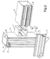
- the embodiments shown in the drawing show the use of a post profile 1 for one Posts and bars in the form of profiles existing Frame construction, in particular such for with Infill in the form of, for example Insulating glass panes provided facades or the like.
- the post profile 1 is arranged with a centrally, extending in the longitudinal direction of the profile Terminal block 2 for one of the infills on the outside comprehensive, not shown in the drawing Cover profile and with both sides of the terminal block. 2 extending seal receiving grooves 3 provided.
- the Terminal block 2 and the Dichtungsabilitynuten 3 form between each one substantially vertical running drainage channel 4.
- At the post profile 1 can also have a Terminal block 5, with Dichtungsabilitynuten 6 and a intervening, substantially horizontal Drainage channel 7 and with a notch 8 provided, special latch profile 9 arranged so be that it is the post profile 1 in the notch area overlapped such that the drainage channels 7 of the Riegel 9 lead into the post 1.
- the bar 9 is otherwise in the field of Dichtungsabilitynuten 3 bolted to the post 1.
- the Post profile 1 in addition or alternative to the special Bar profile 9 is used as a bar 10, wherein the Latch 10 dull abuts the post profile 1 and means one in the hollow profile of the bolt 10, on Post profile 1 connected connector 11 attached is. Furthermore, the educated by the post profile 1 contributes Latch 10 a the terminal block 5 encompassing, on the Dichtungsabilitynuten 6 resting Bar top profile 12, which extends over the Dichtungsabilitynuten 3 of the post 1 to the Drainage channel 4 extends towards.
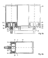
- This latch attachment profile 12 is in turn with Entskyssanssrinnen 13 forming Dichtungsagenuten 14th provided or carries, as shown in Figs. 5 and 6, molded sealing strips 15.
- the post 1 can also be a Bar top profile 12 similar post top section 16 wear, as is also the case from the Embodiment of FIGS. 5 and 6 results.
- the Bar attachment profile 12 made of polyamide (PA), polypropylene (PP), polyvinyl chloride (PVC), ABS or similar Plastic exist.
- Seal receiving grooves 14 and the sealing strips 15th integrally coextruded as a "hard-soft combination for example, formed of TPE.
- the latch attachment profile 12 in the region of Terminal block 5 of FIG. 3 b) with a receiving zone be provided for a Dämmsteg.
- the latch attachment profile 12 in the region of Terminal block 5 also with an integrated Dämmsteg be provided according to FIG. 3 d).
- FIGS 4 c) and d) shown possibility that the latch attachment profile 12th with a U-shaped bar 17 positively into the groove the terminal block 5 engages.
- the invention provides that the inner latch seal 15, the latch attachment profile 12th embraces edge and up to the bar forming Post profile 10 extends, as shown in Figures 3 and 4 each b) to d) can be seen.
- Embodiment of the invention take over Bolt attachment profile 12 and the post attachment profile 16 at the same time the task of sealing. They persist advantageously of EPDM or a comparable Elastomer.
- the post-top profile 16 is the walls the drainage channel 4 of the post 1, while the Bar top section 12 the drainage channel 7 of Bar 10 just covered.
Landscapes
- Engineering & Computer Science (AREA)
- Architecture (AREA)
- Physics & Mathematics (AREA)
- Electromagnetism (AREA)
- Civil Engineering (AREA)
- Structural Engineering (AREA)
- Joining Of Building Structures In Genera (AREA)
- Joining Of Corner Units Of Frames Or Wings (AREA)
- Load-Bearing And Curtain Walls (AREA)
Abstract
Description
- Fig. 1
- eine Rahmenkonstruktion mit abweichend voneinander gestalteten Pfosten- und Riegelprofilen,
- Fig. 2
- eine Rahmenkonstruktion, bei welcher das Pfostenprofil nach Fig. 1 sowohl für den Pfosten wie auch den Riegel eingesetzt wird,
- Fig. 3
- die Rahmenkonstruktion gemäß Fig. 2, wobei in Teilfigur a) der Pfosten und in den Teilfiguren b) - d) der Riegel in alternativen Ausgestaltungen wiedergegeben sind,
- Fig. 4
- die Rahmenkonstruktion gemäß Fig. 2, wobei in Teilfigur a) der Pfosten und in den Teilfiguren b) - d) der Riegel in weiteren alternativen Ausgestaltungen wiedergegeben sind,
- Fig. 5
- eine weitere Rahmenkonstruktion, bei welcher ebenfalls das Pfostenprofil nach Fig. 1 sowohl für den Pfosten wie auch den Riegel eingesetzt wird, wobei in Teilfigur a) der Pfosten und der Riegel (in 90° gedrehter Darstellung) und in Teilfigur b) nur der Riegel wiedergegeben sind,
- Fig. 6
- die Rahmenkonstruktion nach Fig. 5 mit einem der Fig 3 b) entsprechenden Führungsprofil.
Claims (12)
- Verwendung eines Pfostenprofils für eine aus Pfosten und Riegeln in Form von Profilen bestehende Rahmenkonstruktion, insbesondere für mit Ausfachungen in Form von beispielsweise Isolierglasscheiben versehenen Fassaden oder dergleichen, das mit einer mittig angeordneten, sich in Längsrichtung des Profils erstreckenden Anschlußleiste für ein die Ausfachungen außenseitig übergreifendes Deckprofil sowie mit beidseits der Anschlußleiste verlaufenden Dichtungsaufnahmenuten versehen ist, die jeweils zwischen sich und der Anschlußleiste eine im wesentlichen vertikal verlaufende Entwässerungsrinne bilden, wobei am Pfostenprofil ein ebenfalls mit einer Anschlußleiste, mit Dichtungsaufnahmenuten und einer dazwischen verlaufenden, im wesentlichen horizontalen Entwässerungsrinne sowie mit einer Ausklinkung versehenes, spezielles Riegelprofil so angeordnet werden kann, daß es das Pfostenprofil im Ausklinkungsbereich derart überlappt, daß die Entwässerungsrinnen des Riegels in die des Pfostens münden und daß ferner der Riegel im Bereich der Dichtungsaufnahmenuten mit dem Pfosten verschraubt ist,
in der Weise,
daß das Pfostenprofil (1) zusätzlich oder alternativ zum speziellen Riegelprofil (9) als Riegel (10) eingesetzt wird, wobei der Riegel (10) stumpf am Pfostenprofil (1) anstößt und mittels eines in das Hohlprofil des Riegels (10) greifenden, am Pfostenprofil (1) angeschlossenen Verbinders (11) befestigt ist, wobei ferner der vom Pfostenprofil (1) gebildete Riegel (10) ein die Anschlußleiste (5) umgreifendes, auf den Dichtungsaufnahmenuten (6) aufliegendes Riegelaufsatzprofil (12) trägt, das sich über die Dichtungsaufnahmenuten (3) des Pfostens (1) bis zur Entwässerungsrinne (4) hin erstreckt und seinerseits mit Entwässerungsrinnen (13) bildenden Dichtungsaufnahmenuten (14) versehen ist oder angeformte Dichtungsleisten (15) trägt, und wobei zusätzlich auch der Pfosten (1) ein dem Riegelaufsatzprofil (12) ähnliches Pfostenaufsatzprofil (16) tragen kann. - Verwendung eines Pfostenprofils nach Anspruch 1, dadurch gekennzeichnet, daß das Riegelaufsatzprofil (12) aus Polyamid (PA), Polypropylen (PP), Polyvinylchlorid (PVC), ABS oder vergleichbarem Kunststoff besteht.
- Verwendung eines Pfostenprofils nach Anspruch 1 oder 2, dadurch gekennzeichnet, daß das Riegelaufsatzprofil (12) im Bereich der Anschlußleiste (5) mit einer Aufnahmezone für einen Dämmsteg versehen ist.
- Verwendung eines Pfostenprofils nach Anspruch 1 oder 2, dadurch gekennzeichnet, daß das Riegelaufsatzprofil (12) im Bereich der Anschlußleiste (5) mit einer Aufnahmezone für einen Dichtungsschaumkeder (21) versehen ist.
- Verwendung eines Pfostenprofils nach Anspruch 1 oder 2, dadurch gekennzeichnet, daß das Riegelaufsatzprofil (12) im Bereich der Anschlußleiste (5) mit einem integrierten Dämmsteg versehen ist.
- Verwendung eines Pfostenprofils nach einem der Ansprüche 1 bis 5, dadurch gekennzeichnet, daß das Riegelaufsatzprofil (12) mit einer U-förmigen Leiste (17) formschlüssig in die Nut der Anschlußleiste (5) greift.
- Verwendung eines Pfostenprofils nach einem der Ansprüche 1 bis 5, dadurch gekennzeichnet, daß die innere Riegeldichtung (15) das Riegelaufsatzprofil (12) randseitig umgreift und sich bis zum den Riegel bildenden Pfostenprofil (10) erstreckt.
- Verwendung eines Pfostenprofils nach Anspruch 1, dadurch gekennzeichnet, daß das Riegelaufsatzprofil (12) und das Pfostenaufsatzprofil (16) aus EPDM oder einem vergleichbaren Elastomer besteht.
- Verwendung eines Pfostenprofils nach Anspruch 8, dadurch gekennzeichnet, daß das Riegelaufsatzprofil (12) mit der inneren Riegeldichtung (15) sowie das Pfostenaufsatzprofil (16) mit der inneren Pfostendichtung (18) jeweils einstückig ausgebildet sind.
- Verwendung eines Pfostenprofils nach Anspruch 9, dadurch gekennzeichnet, daß das Riegelaufsatzprofil (12) mit der inneren Riegeldichtung (15) sowie das Pfostenaufsatzprofil (16) mit der inneren Pfostendichtung (18) jeweils nur im Randbereich (19) miteinander verbunden und im übrigen über einen Trennspalt (20) einander anliegen.
- Verwendung eines Pfostenprofils nach einem der Ansprüche 8 bis 10, dadurch gekennzeichnet, daß das Pfostenaufsatzprofil (12) den Wänden der Entwässerungsrinne (4) des Pfostens (1) anliegt, während das Riegelaufsatzprofil (12) die Entwässerungsrinne (7) des den Riegel bildenden Pfostenprofils (10) eben überdeckt.
- Verwendung eines Pfostenprofils nach einem der Ansprüche 8 bis 11, dadurch gekennzeichnet, daß das Riegelaufsatzprofil (12) sowie das Pfostenaufsatzprofil (16) mit in die Dichtungsaufnahmenuten (3,6) des Pfostenprofils (1,10) greifenden Verankerungsleisten (21) versehen sind.
Applications Claiming Priority (2)
| Application Number | Priority Date | Filing Date | Title |
|---|---|---|---|
| DE200410014265 DE102004014265A1 (de) | 2004-03-24 | 2004-03-24 | Verwendung eines Pfostenprofils für eine aus Pfosten und Riegeln in Form von Hohlprofilen bestehende Rahmenkonstruktion |
| DE102004014265 | 2004-03-24 |
Publications (2)
| Publication Number | Publication Date |
|---|---|
| EP1580342A2 true EP1580342A2 (de) | 2005-09-28 |
| EP1580342A3 EP1580342A3 (de) | 2012-03-07 |
Family
ID=34854016
Family Applications (1)
| Application Number | Title | Priority Date | Filing Date |
|---|---|---|---|
| EP04021876A Withdrawn EP1580342A3 (de) | 2004-03-24 | 2004-09-15 | Pfostenprofils für eine aus Pfosten und Riegeln in Form von Hohlprofilen bestehende Rahmenkonstruktion |
Country Status (2)
| Country | Link |
|---|---|
| EP (1) | EP1580342A3 (de) |
| DE (1) | DE102004014265A1 (de) |
Families Citing this family (1)
| Publication number | Priority date | Publication date | Assignee | Title |
|---|---|---|---|---|
| DE102020111612B4 (de) | 2020-04-29 | 2023-06-29 | HUECK System GmbH & Co. KG | Verbinderanordnung zum winkligen verbinden von jeweils ein anschlussprofil und ein aufschiebprofil umfassenden hohlprofilen sowie einer profilanordnung mit einer solchen verbinderanordnung |
Family Cites Families (10)
| Publication number | Priority date | Publication date | Assignee | Title |
|---|---|---|---|---|
| DE4210575A1 (de) * | 1992-03-31 | 1993-10-07 | Herbert Lacker | Unterkonstruktion für Glasdächer und Glasfassaden |
| EP0619403B1 (de) * | 1993-04-07 | 1996-10-16 | W. HARTMANN & CO (GMBH & CO) | Aussenwandkonstruktion für Gebäude oder Schrägdächer |
| DE4332406A1 (de) * | 1993-09-23 | 1995-03-30 | Heroal Johann Henkenjohann Gmb | Pfosten-Riegel-System |
| DE29603707U1 (de) * | 1996-02-29 | 1996-04-18 | Raico Bautechnik GmbH, 87746 Erkheim | Metallfassade |
| DE19741469A1 (de) * | 1997-09-19 | 1999-03-25 | Sommer Metallbau Stahlbau Gmbh | Vorrichtung zum Befestigen von Verglasungen, Fassaden oder dergleichen an einem Anschlußprofil |
| DE19830087C2 (de) * | 1998-07-06 | 2000-09-14 | Gutmann Hermann Werke Gmbh | Gebäudefassade oder Dachfassade mit einem Rahmenwerk aus Pfosten und Riegeln |
| DE19849152C5 (de) * | 1998-10-26 | 2013-10-10 | Gutmann Ag | Pfosten-Riegelverbindung |
| DE20100747U1 (de) * | 2001-01-15 | 2001-03-08 | Schüco International KG, 33609 Bielefeld | Riegel/Pfosten-Konstruktion |
| DE10223038B4 (de) * | 2002-05-22 | 2004-09-16 | Akotherm Ne Metallhandelsgesellschaft Mbh | Fassadenkonstruktion mit einem durch ein Dichtelement abgedichteten riegelseitigen Isolierprofil |
| DE20219276U1 (de) * | 2002-12-12 | 2003-03-13 | Evg Bauprofil System Entwicklungs- Und Vermarktungsgesellschaft Mbh, Eugendorf | Innendichtung mit Füllungsdickenausgleich |
-
2004
- 2004-03-24 DE DE200410014265 patent/DE102004014265A1/de not_active Withdrawn
- 2004-09-15 EP EP04021876A patent/EP1580342A3/de not_active Withdrawn
Also Published As
| Publication number | Publication date |
|---|---|
| EP1580342A3 (de) | 2012-03-07 |
| DE102004014265A1 (de) | 2005-10-20 |
Similar Documents
| Publication | Publication Date | Title |
|---|---|---|
| WO2005068764A1 (de) | Rahmen für eine schiebetür oder ein schiebefenster | |
| DE3639848C2 (de) | ||
| DE2948017A1 (de) | Verfahren zur herstellung von mehrscheiben-isolierglas | |
| EP4299870B1 (de) | Blendrahmen für eine tür mit extrusionsrahmen und schwelle, tür mit einem derartigen blendrahmen und verfahren zur herstellung dieser tür | |
| DE202014010902U1 (de) | Isolierelement für Fassaden- oder Lichtdachkonstruktionen | |
| EP2045431A2 (de) | Außenverkleidung mit integrierter Wärmedämmung | |
| DE102009051070A1 (de) | Wandsystem | |
| DE9407033U1 (de) | Fenster- oder Türrahmen mit darauf befestigtem Schließblech und darin eingreifendem Schließbolzen | |
| EP0690951A1 (de) | Alu-holz-verbundprofil | |
| DE2313662A1 (de) | Fenster und verfahren zu seiner herstellung | |
| DE10319001A1 (de) | Fassade oder Dach mit mehreren Entwässerungsebenen | |
| EP1580342A2 (de) | Verwendung eines Pfostenprofils für eine aus Pfosten und Riegeln in Form von Hohlprofilen bestehende Rahmenkonstruktion | |
| DE2235858A1 (de) | Verbindungseinrichtung fuer aus profilstaeben und einer isolierglasscheibe bestehende fluegel fuer fenster, tueren od. dgl | |
| DE102008022650A1 (de) | Gebäudefassade oder Dachfassade mit Ausfachungen | |
| EP1596022A2 (de) | Andruckleiste für eine Gebäudefassade oder ein Dach | |
| EP1577455B1 (de) | Gebäudefassade oder Dach mit Ausfachungen zur Aufnahme von Fassadenelementen | |
| EP3670806A1 (de) | Verfahren zum befestigen eines profils an einem stab | |
| EP1103691B1 (de) | Eckverbinder für Falzverbreiterungen | |
| EP2853676A2 (de) | Schiebeflügel und Insektenschutz-Schiebeanlage | |
| EP3176340B1 (de) | Dichtung, sowie pfosten-riegel-anordnung | |
| DE19622725C2 (de) | Gebäudefenster und/oder Gebäudefenstertür | |
| DE202007009167U1 (de) | Fassadensystem mit Dichtungsschienenverschlussmitteln | |
| EP4174242B1 (de) | Dichtungsanordnung zur abdichtung des übergangs zwischen fassadenelementen einer elementfassade | |
| EP2072744A2 (de) | Zargenprofil für eine Hebe-Schiebetür | |
| DE102006050572B4 (de) | Profilrahmen |
Legal Events
| Date | Code | Title | Description |
|---|---|---|---|
| PUAI | Public reference made under article 153(3) epc to a published international application that has entered the european phase |
Free format text: ORIGINAL CODE: 0009012 |
|
| AK | Designated contracting states |
Kind code of ref document: A2 Designated state(s): AT BE BG CH CY CZ DE DK EE ES FI FR GB GR HU IE IT LI LU MC NL PL PT RO SE SI SK TR |
|
| AX | Request for extension of the european patent |
Extension state: AL HR LT LV MK |
|
| PUAL | Search report despatched |
Free format text: ORIGINAL CODE: 0009013 |
|
| AK | Designated contracting states |
Kind code of ref document: A3 Designated state(s): AT BE BG CH CY CZ DE DK EE ES FI FR GB GR HU IE IT LI LU MC NL PL PT RO SE SI SK TR |
|
| AX | Request for extension of the european patent |
Extension state: AL HR LT LV MK |
|
| RIC1 | Information provided on ipc code assigned before grant |
Ipc: E04B 2/96 20060101AFI20120130BHEP |
|
| STAA | Information on the status of an ep patent application or granted ep patent |
Free format text: STATUS: THE APPLICATION IS DEEMED TO BE WITHDRAWN |
|
| 18D | Application deemed to be withdrawn |
Effective date: 20120403 |