EP1580046A2 - Moteur rotatif double et méthode de contrôle correspondante - Google Patents
Moteur rotatif double et méthode de contrôle correspondante Download PDFInfo
- Publication number
- EP1580046A2 EP1580046A2 EP04025256A EP04025256A EP1580046A2 EP 1580046 A2 EP1580046 A2 EP 1580046A2 EP 04025256 A EP04025256 A EP 04025256A EP 04025256 A EP04025256 A EP 04025256A EP 1580046 A2 EP1580046 A2 EP 1580046A2
- Authority
- EP
- European Patent Office
- Prior art keywords
- motor
- stabilizer
- housing
- pivot
- pivoting
- Prior art date
- Legal status (The legal status is an assumption and is not a legal conclusion. Google has not performed a legal analysis and makes no representation as to the accuracy of the status listed.)
- Granted
Links
Images

Classifications
-
- B—PERFORMING OPERATIONS; TRANSPORTING
- B60—VEHICLES IN GENERAL
- B60G—VEHICLE SUSPENSION ARRANGEMENTS
- B60G21/00—Interconnection systems for two or more resiliently-suspended wheels, e.g. for stabilising a vehicle body with respect to acceleration, deceleration or centrifugal forces
- B60G21/02—Interconnection systems for two or more resiliently-suspended wheels, e.g. for stabilising a vehicle body with respect to acceleration, deceleration or centrifugal forces permanently interconnected
- B60G21/04—Interconnection systems for two or more resiliently-suspended wheels, e.g. for stabilising a vehicle body with respect to acceleration, deceleration or centrifugal forces permanently interconnected mechanically
- B60G21/05—Interconnection systems for two or more resiliently-suspended wheels, e.g. for stabilising a vehicle body with respect to acceleration, deceleration or centrifugal forces permanently interconnected mechanically between wheels on the same axle but on different sides of the vehicle, i.e. the left and right wheel suspensions being interconnected
- B60G21/055—Stabiliser bars
- B60G21/0551—Mounting means therefor
- B60G21/0553—Mounting means therefor adjustable
- B60G21/0555—Mounting means therefor adjustable including an actuator inducing vehicle roll
-
- B—PERFORMING OPERATIONS; TRANSPORTING
- B60—VEHICLES IN GENERAL
- B60G—VEHICLE SUSPENSION ARRANGEMENTS
- B60G21/00—Interconnection systems for two or more resiliently-suspended wheels, e.g. for stabilising a vehicle body with respect to acceleration, deceleration or centrifugal forces
- B60G21/10—Interconnection systems for two or more resiliently-suspended wheels, e.g. for stabilising a vehicle body with respect to acceleration, deceleration or centrifugal forces not permanently interconnected, e.g. operative only on acceleration, only on deceleration or only at off-straight position of steering
- B60G21/106—Interconnection systems for two or more resiliently-suspended wheels, e.g. for stabilising a vehicle body with respect to acceleration, deceleration or centrifugal forces not permanently interconnected, e.g. operative only on acceleration, only on deceleration or only at off-straight position of steering transversally
-
- B—PERFORMING OPERATIONS; TRANSPORTING
- B60—VEHICLES IN GENERAL
- B60G—VEHICLE SUSPENSION ARRANGEMENTS
- B60G2202/00—Indexing codes relating to the type of spring, damper or actuator
- B60G2202/10—Type of spring
- B60G2202/13—Torsion spring
- B60G2202/135—Stabiliser bar and/or tube
- B60G2202/1351—Stabiliser bar and/or tube comprising at least two stabiliser bars parallel to each other
-
- B—PERFORMING OPERATIONS; TRANSPORTING
- B60—VEHICLES IN GENERAL
- B60G—VEHICLE SUSPENSION ARRANGEMENTS
- B60G2202/00—Indexing codes relating to the type of spring, damper or actuator
- B60G2202/40—Type of actuator
- B60G2202/42—Electric actuator
-
- B—PERFORMING OPERATIONS; TRANSPORTING
- B60—VEHICLES IN GENERAL
- B60G—VEHICLE SUSPENSION ARRANGEMENTS
- B60G2800/00—Indexing codes relating to the type of movement or to the condition of the vehicle and to the end result to be achieved by the control action
- B60G2800/01—Attitude or posture control
- B60G2800/012—Rolling condition
Definitions
- the invention relates to a swivel motor for stabilizers in motor vehicles and a method for Control of the slew motor.
- a swivel motor for stabilizers in motor vehicles known, which is arranged between two stabilizer halves and the stabilizer halves against each other can pivot. This makes it possible to compensate for rolling movements of the vehicle.
- the Stabilizer consists of a housing in which a rotor is pivotally mounted. Between wings of the Rotor and vanes of the housing are formed chambers which upon pressurization to a Rotate the rotor relative to the housing. The case is the first Stabilizer half and the rotor connected to the second stabilizer half.
- a second Swing motor to use, which acts on the housing of the first swing motor.
- the housing of the first pivot motor part of the second swing motor, so that the number the necessary components is reduced.
- the housing of the first pivoting motor as Rotor of the second swing motor used.
- a second pivot motor is provided, so its housing can be part of an advantageous manner be an axle cross member. This construction saves weight and installation space; simultaneously can an otherwise necessary coupling member between the housing of the second pivot motor and the Body can be saved.
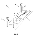
- Fig. 1 shows schematically a front axle 1 of a motor vehicle not shown in detail with McPherson Suspension struts 2, which are coupled to one another via a stabilizer 3.
- the stabilizer 3 has two Stabilizer halves 3a and 3b, which are each connected via coupling links 4 with the struts 2. Between the stabilizer halves 3a and 3b, a pivot motor 5 is arranged.
- An outer housing 6 the swing motor 5 is connected via a further coupling member 7 with a cross member 8 of the chassis or connected to another body-mounted component.
- the stabilizer halves 3a, 3b are in bearings 9 held pivotally, the bearings 9 also on the cross member 8 or another body or fixed chassis component are held.
- Fig. 2 shows the pivot motor 5 in the main section.
- an inner housing 9 is rotatable stored.
- the inner housing 9 in turn receives a rotor 10.
- the inner housing 9 is connected to the first stabilizer half 3a, the rotor 10 rotatably connected to the second stabilizer half 3b.
- Of the Rotor 10 is provided on its outside with wings 11.
- the inner housing 9 has on its inside Wing 12 and on its outside wings 13 on.
- the outer housing 6 has wings on its inside 14 on.
- a formed between the outer housing 6 and the inner housing 9 annular space 15 is through the Wing 13, 14 divided into chambers 16a, 16b, 17a, 17b. Opposite chambers 16a, 16b and 17a, 17b are connected together and pressurized together. A Pressurization of the chambers 16, for example, leads to a pivoting of the inner housing 9 in the direction of arrow R. Since the outer housing 6 is held via the coupling member 7 fixed to the body, means this simultaneously pivoting of the inner housing 9 relative to the body, here the cross member 8, in the direction of the arrow R.
- annular space 18 is formed between the inner housing 9 and the rotor 10, the is divided by the wings 11, 12 in chambers 19a, 19b, 20a, 20b.
- the pressure medium supply lines to the chambers 16, 17, 19 and 20 are not shown in detail and take place in known manner via hose lines.
- the action of the swing motor 5 is as follows.
- the inner casing 9 and the rotor 10 constitute one known first pivot motor 21, the movement of the two stabilizer halves 3a, 3b controlled to each other.
- the stabilizer 3 pivot freely relative to the body 8 of the vehicle, wherein the Rotation angle position of the stabilizer halves 3a, 3b to each other by the position of the first pivot motor 21 is determined.
- a second pivot motor 22 is formed by the outer housing 6 and the inner housing 9, wherein the inner housing 9 acts as a rotor to the outer housing 6.
- the first Pivoting motor 21 can be set or pivoted relative to the body 8.
- the second pivot motor 22 acts only on the first stabilizer half 3a directly, as this with the inner housing 9 is rotatably connected.
- pressurization of the second pivot motor 22 So can the Radaufstandskraft on the connected to the first stabilizer half 3a strut 2 directly to be influenced; the size of the influence results from the torsional rigidity of the first Stabilizer half 3a and the pivot angle of the stabilizer half 3a against a neutral, force-free Position.
- the movement of the second stabilizer half 3b relative to the body 8 takes place indirectly via both Swing motors 21,22. So to move only the first stabilizer half 3a and the second Stabilizer half 3b hold in position, the two pivot motors 21,22 in opposite directions be controlled.
- the two pivot motors 21, 22 are activated in such a way that the first Swing motor 21 in the sense of roll compensation and the second pivot motor 22 in the sense of Nick compensated is driven. Both compensation functions are due to the two swivel motors 21,22 advantageously controlled separately from each other.
Landscapes
- Engineering & Computer Science (AREA)
- Mechanical Engineering (AREA)
- Vehicle Body Suspensions (AREA)
- Bending Of Plates, Rods, And Pipes (AREA)
Applications Claiming Priority (2)
| Application Number | Priority Date | Filing Date | Title |
|---|---|---|---|
| DE102004002550A DE102004002550A1 (de) | 2004-01-17 | 2004-01-17 | Doppelter Schwenkmotor und Verfahren zur Ansteuerung |
| DE102004002550 | 2004-01-17 |
Publications (3)
| Publication Number | Publication Date |
|---|---|
| EP1580046A2 true EP1580046A2 (fr) | 2005-09-28 |
| EP1580046A3 EP1580046A3 (fr) | 2005-10-12 |
| EP1580046B1 EP1580046B1 (fr) | 2008-03-19 |
Family
ID=34716639
Family Applications (1)
| Application Number | Title | Priority Date | Filing Date |
|---|---|---|---|
| EP04025256A Expired - Lifetime EP1580046B1 (fr) | 2004-01-17 | 2004-10-23 | Moteur rotatif double et méthode de contrôle correspondante |
Country Status (3)
| Country | Link |
|---|---|
| EP (1) | EP1580046B1 (fr) |
| AT (1) | ATE389554T1 (fr) |
| DE (2) | DE102004002550A1 (fr) |
Cited By (1)
| Publication number | Priority date | Publication date | Assignee | Title |
|---|---|---|---|---|
| US9108482B2 (en) | 2013-02-16 | 2015-08-18 | Audi Ag | Torsion bar spring arrangement for a wheel suspension of a motor vehicle |
Families Citing this family (13)
| Publication number | Priority date | Publication date | Assignee | Title |
|---|---|---|---|---|
| DE102005031414B4 (de) * | 2005-07-04 | 2016-01-21 | Bayerische Motoren Werke Aktiengesellschaft | Schwenkmotor |
| DE102005047278A1 (de) * | 2005-10-01 | 2007-04-05 | Bayerische Motoren Werke Ag | Schwenkmotor-Anordnung in einem geteilten Stabilisator eines Fahrzeugs |
| DE102006009524A1 (de) * | 2006-02-28 | 2007-09-06 | Pnp Automotive Gmbh | Stabilisator für ein Kraftfahrzeug |
| US8148055B2 (en) | 2006-06-30 | 2012-04-03 | Infineon Technologies Ag | Method for developing a photoresist |
| DE102007007214A1 (de) | 2007-02-14 | 2008-08-21 | Volkswagen Ag | Anordnung eines Stabilisators an einer Radaufhängung für Kraftfahrzeuge |
| DE102007022179A1 (de) * | 2007-05-11 | 2008-11-13 | Bayerische Motoren Werke Aktiengesellschaft | Schwenkmotor, insbesondere für einen geteilten Querstabilisator eines Fahrzeugs |
| EP2065231A1 (fr) * | 2007-11-30 | 2009-06-03 | Nederlandse Organisatie voor Toegepast-Natuuurwetenschappelijk Onderzoek TNO | Ensemble de stabilisation de roulis de façon active alimenté par des supports de pompe à direction assistée, répartition de débit actif, régulateur de débit actif et véhicule comportant un tel ensemble de stabilisation de roulis de façon active |
| DE102009005895A1 (de) | 2009-01-23 | 2010-07-29 | Audi Ag | Anordnung eines Stabilisators an einer Radaufhängung für Kraftfahrzeuge |
| DE102009005899A1 (de) | 2009-01-23 | 2010-07-29 | Audi Ag | Anordnung eines Stabilisators an einer Radaufhängung für Kraftfahrzeuge |
| DE102009005898A1 (de) | 2009-01-23 | 2010-07-29 | Audi Ag | Anordnung eines Stabilisators an einer Radaufhängung für Kraftfahrzeuge |
| DE102010041404A1 (de) * | 2010-09-27 | 2012-03-29 | Zf Friedrichshafen Ag | Aktiver Torsionswankstabilisator |
| DE102012011919A1 (de) | 2012-06-15 | 2013-12-19 | Audi Ag | Verstellbare Radaufhängung für die Räder einer Achse eines Kraftfahrzeugs |
| DE102012011918A1 (de) | 2012-06-15 | 2013-12-19 | Audi Ag | Verstellbare Radaufhängung für die Räder einer Achse eines Kraftfahrzeugs |
Family Cites Families (14)
| Publication number | Priority date | Publication date | Assignee | Title |
|---|---|---|---|---|
| US2106886A (en) * | 1936-02-12 | 1938-02-01 | Houde Eng Corp | Stabilizer structure for automobiles |
| US2208969A (en) * | 1938-07-30 | 1940-07-23 | Nevin S Focht | Stabilizing means for vehicle bodies |
| DE1105290B (de) * | 1959-10-31 | 1961-04-20 | Daimler Benz Ag | Vorrichtung zur Kurvenstabilisierung des Wagenkastens bei Kraftfahrzeugen, insbesondere solchen mit Luftfederung |
| NL267764A (fr) * | 1960-08-03 | |||
| DE1755837A1 (de) * | 1968-06-28 | 1971-12-30 | Daimler Benz Ag | Abfederung von Kraftfahrzeugen mit Stabilisator |
| DE2019372A1 (de) * | 1970-04-22 | 1971-11-04 | Messerschmitt Boelkow Blohm | Druckmittelbetaetigter Stellmotor |
| JPS5143521A (en) * | 1974-10-14 | 1976-04-14 | Nissan Motor | Jidoshano kagensokujishataishiseiseigyosochi |
| JP3092090B2 (ja) * | 1991-10-03 | 2000-09-25 | カヤバ工業株式会社 | スタビライザ制御装置 |
| DE29521157U1 (de) * | 1995-09-12 | 1996-09-05 | Fichtel & Sachs Ag, 97424 Schweinfurt | Fahrzeugachse mit verstellbarem Stabilisator |
| DE19754539C2 (de) * | 1997-12-09 | 2001-11-29 | Mannesmann Sachs Ag | Schwenkmotor |
| DE19802489A1 (de) * | 1998-01-23 | 1999-03-11 | Daimler Benz Ag | Mehrachsiger, motorgetriebener Kraftwagen, insbesondere Personenkraftwagen |
| DE19930444C5 (de) * | 1999-07-02 | 2005-10-20 | Daimler Chrysler Ag | Stabilisatoranordnung für ein Kraftfahrzeug |
| NL1019456C2 (nl) * | 2001-11-30 | 2003-06-03 | Skf Ab | Stabilisatorsysteem voor een voertuig. |
| DE10242552B4 (de) * | 2002-09-13 | 2004-09-16 | Audi Ag | Vorrichtung zum elektromechanischen Verstellen |
-
2004
- 2004-01-17 DE DE102004002550A patent/DE102004002550A1/de not_active Withdrawn
- 2004-10-23 DE DE502004006569T patent/DE502004006569D1/de not_active Expired - Lifetime
- 2004-10-23 EP EP04025256A patent/EP1580046B1/fr not_active Expired - Lifetime
- 2004-10-23 AT AT04025256T patent/ATE389554T1/de not_active IP Right Cessation
Cited By (1)
| Publication number | Priority date | Publication date | Assignee | Title |
|---|---|---|---|---|
| US9108482B2 (en) | 2013-02-16 | 2015-08-18 | Audi Ag | Torsion bar spring arrangement for a wheel suspension of a motor vehicle |
Also Published As
| Publication number | Publication date |
|---|---|
| EP1580046A3 (fr) | 2005-10-12 |
| ATE389554T1 (de) | 2008-04-15 |
| EP1580046B1 (fr) | 2008-03-19 |
| DE102004002550A1 (de) | 2005-08-04 |
| DE502004006569D1 (de) | 2008-04-30 |
Similar Documents
| Publication | Publication Date | Title |
|---|---|---|
| EP1580046B1 (fr) | Moteur rotatif double et méthode de contrôle correspondante | |
| EP2956315B1 (fr) | Suspension de roue conçue pour un véhicule automobile | |
| EP2246204B1 (fr) | Suspension à roues indépendantes | |
| DE102014011193B4 (de) | Vorrichtung zum Verstellen von Sturz und/oder Spur eines Fahrzeugrads mit einer Bremsmomentabstützung | |
| DE102013216029B4 (de) | Lenkbare Vorderachse für Räder eines zweispurigen Kraftfahrzeugs und zweispuriges Kraftfahrzeug mit einer solchen Vorderachse | |
| DE102014201876A1 (de) | Vorrichtung zum Einstellen der Spur und/oder des Sturzes für ein Fahrwerk eines Kraftfahrzeugs | |
| DE102012108552B4 (de) | Aktives wankstabilisierungssystem | |
| DE3809995A1 (de) | Hintere aufhaengungseinrichtung fuer motorfahrzeuge | |
| DE102008044103A1 (de) | Radaufhängung für ein lenkbares Fahrzeugrad, insbesondere eines Nutzkraftfahrzeuges | |
| DE102005037973A1 (de) | Einrichtung zur Verstellung des Radsturzes oder der Vorspur | |
| DE102010061018A1 (de) | Radaufhängung eines Kraftfahrzeugs | |
| EP3172069B1 (fr) | Dispositif pour régler le carrossage et/ou parallélisme d'un roue d'un véhicule | |
| EP1900616B1 (fr) | Suspension de la cabine conducteur | |
| WO2016202513A1 (fr) | Liaison articulée et système pour la suspension d'une roue | |
| DE102015202208A1 (de) | Verfahren zum Betrieb einer Hinterradlenkung sowie Hinterradlenkung für ein Fahrzeug | |
| DE102020113947A1 (de) | Radaufhängung für eine Fahrzeug-Hinterachse | |
| DE102015014027A1 (de) | Radaufhängung für ein Fahrzeug | |
| DE102014214229A1 (de) | Lenkung für eine Verbundlenkerachse | |
| DE102012221699A1 (de) | Radaufhängung für ein Fahrzeug mit aktiver Radsturzverstellung | |
| DE102011088178A1 (de) | Achse eines zweispurigen Fahrzeugs mit einem Längslenker | |
| DE102010039245A1 (de) | Verbundlenkerachse für ein Fahrzeug | |
| DE10329689A1 (de) | Achsaufhängung für Kraftfahrzeuge | |
| DE102016222157A1 (de) | Aufgelöste McPherson-Radaufhängung | |
| DE202015101117U1 (de) | Einzelradaufhängung sowie Hinterachse mit Einzelradaufhängungen für ein Fahrzeug | |
| DE102018002855A1 (de) | Federbeinachse mit hohen Lenkwinkeln |
Legal Events
| Date | Code | Title | Description |
|---|---|---|---|
| PUAI | Public reference made under article 153(3) epc to a published international application that has entered the european phase |
Free format text: ORIGINAL CODE: 0009012 |
|
| PUAL | Search report despatched |
Free format text: ORIGINAL CODE: 0009013 |
|
| AK | Designated contracting states |
Kind code of ref document: A2 Designated state(s): AT BE BG CH CY CZ DE DK EE ES FI FR GB GR HU IE IT LI LU MC NL PL PT RO SE SI SK TR |
|
| AX | Request for extension of the european patent |
Extension state: AL HR LT LV MK |
|
| AK | Designated contracting states |
Kind code of ref document: A3 Designated state(s): AT BE BG CH CY CZ DE DK EE ES FI FR GB GR HU IE IT LI LU MC NL PL PT RO SE SI SK TR |
|
| AX | Request for extension of the european patent |
Extension state: AL HR LT LV MK |
|
| 17P | Request for examination filed |
Effective date: 20060412 |
|
| AKX | Designation fees paid |
Designated state(s): AT DE FR GB IT SE |
|
| GRAP | Despatch of communication of intention to grant a patent |
Free format text: ORIGINAL CODE: EPIDOSNIGR1 |
|
| GRAS | Grant fee paid |
Free format text: ORIGINAL CODE: EPIDOSNIGR3 |
|
| GRAA | (expected) grant |
Free format text: ORIGINAL CODE: 0009210 |
|
| AK | Designated contracting states |
Kind code of ref document: B1 Designated state(s): AT DE FR GB IT SE |
|
| REG | Reference to a national code |
Ref country code: GB Ref legal event code: FG4D Free format text: NOT ENGLISH |
|
| REF | Corresponds to: |
Ref document number: 502004006569 Country of ref document: DE Date of ref document: 20080430 Kind code of ref document: P |
|
| RAP2 | Party data changed (patent owner data changed or rights of a patent transferred) |
Owner name: DR. ING. H.C. F. PORSCHE AKTIENGESELLSCHAFT |
|
| RAP2 | Party data changed (patent owner data changed or rights of a patent transferred) |
Owner name: DR. ING. H.C. F. PORSCHE AKTIENGESELLSCHAFT |
|
| PG25 | Lapsed in a contracting state [announced via postgrant information from national office to epo] |
Ref country code: SE Free format text: LAPSE BECAUSE OF FAILURE TO SUBMIT A TRANSLATION OF THE DESCRIPTION OR TO PAY THE FEE WITHIN THE PRESCRIBED TIME-LIMIT Effective date: 20080619 |
|
| ET | Fr: translation filed | ||
| PLBE | No opposition filed within time limit |
Free format text: ORIGINAL CODE: 0009261 |
|
| STAA | Information on the status of an ep patent application or granted ep patent |
Free format text: STATUS: NO OPPOSITION FILED WITHIN TIME LIMIT |
|
| 26N | No opposition filed |
Effective date: 20081222 |
|
| REG | Reference to a national code |
Ref country code: FR Ref legal event code: TP |
|
| REG | Reference to a national code |
Ref country code: FR Ref legal event code: CD |
|
| PG25 | Lapsed in a contracting state [announced via postgrant information from national office to epo] |
Ref country code: AT Free format text: LAPSE BECAUSE OF NON-PAYMENT OF DUE FEES Effective date: 20081023 |
|
| PGFP | Annual fee paid to national office [announced via postgrant information from national office to epo] |
Ref country code: GB Payment date: 20091022 Year of fee payment: 6 Ref country code: IT Payment date: 20091024 Year of fee payment: 6 |
|
| PGFP | Annual fee paid to national office [announced via postgrant information from national office to epo] |
Ref country code: FR Payment date: 20101104 Year of fee payment: 7 |
|
| REG | Reference to a national code |
Ref country code: FR Ref legal event code: TP |
|
| REG | Reference to a national code |
Ref country code: GB Ref legal event code: 732E Free format text: REGISTERED BETWEEN 20110310 AND 20110316 |
|
| REG | Reference to a national code |
Ref country code: GB Ref legal event code: 732E Free format text: REGISTERED BETWEEN 20110331 AND 20110406 |
|
| GBPC | Gb: european patent ceased through non-payment of renewal fee |
Effective date: 20101023 |
|
| PG25 | Lapsed in a contracting state [announced via postgrant information from national office to epo] |
Ref country code: GB Free format text: LAPSE BECAUSE OF NON-PAYMENT OF DUE FEES Effective date: 20101023 |
|
| PG25 | Lapsed in a contracting state [announced via postgrant information from national office to epo] |
Ref country code: IT Free format text: LAPSE BECAUSE OF NON-PAYMENT OF DUE FEES Effective date: 20101023 |
|
| REG | Reference to a national code |
Ref country code: FR Ref legal event code: ST Effective date: 20120629 |
|
| PG25 | Lapsed in a contracting state [announced via postgrant information from national office to epo] |
Ref country code: FR Free format text: LAPSE BECAUSE OF NON-PAYMENT OF DUE FEES Effective date: 20111102 |
|
| PGFP | Annual fee paid to national office [announced via postgrant information from national office to epo] |
Ref country code: DE Payment date: 20151015 Year of fee payment: 12 |
|
| REG | Reference to a national code |
Ref country code: DE Ref legal event code: R119 Ref document number: 502004006569 Country of ref document: DE |
|
| PG25 | Lapsed in a contracting state [announced via postgrant information from national office to epo] |
Ref country code: DE Free format text: LAPSE BECAUSE OF NON-PAYMENT OF DUE FEES Effective date: 20170503 |