EP1579242B1 - Verbesserung der temperaturkompensation in einem radargerät - Google Patents
Verbesserung der temperaturkompensation in einem radargerät Download PDFInfo
- Publication number
- EP1579242B1 EP1579242B1 EP03768019.6A EP03768019A EP1579242B1 EP 1579242 B1 EP1579242 B1 EP 1579242B1 EP 03768019 A EP03768019 A EP 03768019A EP 1579242 B1 EP1579242 B1 EP 1579242B1
- Authority
- EP
- European Patent Office
- Prior art keywords
- frequency
- signal
- distance
- temperature
- processing means
- Prior art date
- Legal status (The legal status is an assumption and is not a legal conclusion. Google has not performed a legal analysis and makes no representation as to the accuracy of the status listed.)
- Expired - Lifetime
Links
- 238000005259 measurement Methods 0.000 claims description 13
- 230000001105 regulatory effect Effects 0.000 claims description 8
- 230000001419 dependent effect Effects 0.000 claims description 7
- 230000008859 change Effects 0.000 claims description 6
- 230000000694 effects Effects 0.000 claims description 4
- 230000010363 phase shift Effects 0.000 claims description 4
- 230000006870 function Effects 0.000 claims description 2
- 238000009529 body temperature measurement Methods 0.000 claims 1
- 238000012937 correction Methods 0.000 description 6
- 230000005855 radiation Effects 0.000 description 5
- 230000004048 modification Effects 0.000 description 3
- 238000012986 modification Methods 0.000 description 3
- 238000001228 spectrum Methods 0.000 description 3
- 238000010438 heat treatment Methods 0.000 description 2
- XUIMIQQOPSSXEZ-UHFFFAOYSA-N Silicon Chemical compound [Si] XUIMIQQOPSSXEZ-UHFFFAOYSA-N 0.000 description 1
- 230000032683 aging Effects 0.000 description 1
- 230000003679 aging effect Effects 0.000 description 1
- 239000000919 ceramic Substances 0.000 description 1
- 150000001875 compounds Chemical class 0.000 description 1
- 238000001816 cooling Methods 0.000 description 1
- 238000009434 installation Methods 0.000 description 1
- 230000004044 response Effects 0.000 description 1
- 230000035945 sensitivity Effects 0.000 description 1
- 229910052710 silicon Inorganic materials 0.000 description 1
- 239000010703 silicon Substances 0.000 description 1
- 230000001360 synchronised effect Effects 0.000 description 1
Images

Classifications
-
- H—ELECTRICITY
- H03—ELECTRONIC CIRCUITRY
- H03L—AUTOMATIC CONTROL, STARTING, SYNCHRONISATION OR STABILISATION OF GENERATORS OF ELECTRONIC OSCILLATIONS OR PULSES
- H03L1/00—Stabilisation of generator output against variations of physical values, e.g. power supply
- H03L1/02—Stabilisation of generator output against variations of physical values, e.g. power supply against variations of temperature only
- H03L1/022—Stabilisation of generator output against variations of physical values, e.g. power supply against variations of temperature only by indirect stabilisation, i.e. by generating an electrical correction signal which is a function of the temperature
-
- G—PHYSICS
- G01—MEASURING; TESTING
- G01S—RADIO DIRECTION-FINDING; RADIO NAVIGATION; DETERMINING DISTANCE OR VELOCITY BY USE OF RADIO WAVES; LOCATING OR PRESENCE-DETECTING BY USE OF THE REFLECTION OR RERADIATION OF RADIO WAVES; ANALOGOUS ARRANGEMENTS USING OTHER WAVES
- G01S13/00—Systems using the reflection or reradiation of radio waves, e.g. radar systems; Analogous systems using reflection or reradiation of waves whose nature or wavelength is irrelevant or unspecified
- G01S13/02—Systems using reflection of radio waves, e.g. primary radar systems; Analogous systems
- G01S13/50—Systems of measurement based on relative movement of target
- G01S13/58—Velocity or trajectory determination systems; Sense-of-movement determination systems
- G01S13/583—Velocity or trajectory determination systems; Sense-of-movement determination systems using transmission of continuous unmodulated waves, amplitude-, frequency-, or phase-modulated waves and based upon the Doppler effect resulting from movement of targets
- G01S13/584—Velocity or trajectory determination systems; Sense-of-movement determination systems using transmission of continuous unmodulated waves, amplitude-, frequency-, or phase-modulated waves and based upon the Doppler effect resulting from movement of targets adapted for simultaneous range and velocity measurements
-
- G—PHYSICS
- G01—MEASURING; TESTING
- G01S—RADIO DIRECTION-FINDING; RADIO NAVIGATION; DETERMINING DISTANCE OR VELOCITY BY USE OF RADIO WAVES; LOCATING OR PRESENCE-DETECTING BY USE OF THE REFLECTION OR RERADIATION OF RADIO WAVES; ANALOGOUS ARRANGEMENTS USING OTHER WAVES
- G01S7/00—Details of systems according to groups G01S13/00, G01S15/00, G01S17/00
- G01S7/02—Details of systems according to groups G01S13/00, G01S15/00, G01S17/00 of systems according to group G01S13/00
- G01S7/35—Details of non-pulse systems
-
- G—PHYSICS
- G01—MEASURING; TESTING
- G01S—RADIO DIRECTION-FINDING; RADIO NAVIGATION; DETERMINING DISTANCE OR VELOCITY BY USE OF RADIO WAVES; LOCATING OR PRESENCE-DETECTING BY USE OF THE REFLECTION OR RERADIATION OF RADIO WAVES; ANALOGOUS ARRANGEMENTS USING OTHER WAVES
- G01S7/00—Details of systems according to groups G01S13/00, G01S15/00, G01S17/00
- G01S7/02—Details of systems according to groups G01S13/00, G01S15/00, G01S17/00 of systems according to group G01S13/00
- G01S7/40—Means for monitoring or calibrating
- G01S7/4004—Means for monitoring or calibrating of parts of a radar system
- G01S7/4008—Means for monitoring or calibrating of parts of a radar system of transmitters
-
- H—ELECTRICITY
- H03—ELECTRONIC CIRCUITRY
- H03L—AUTOMATIC CONTROL, STARTING, SYNCHRONISATION OR STABILISATION OF GENERATORS OF ELECTRONIC OSCILLATIONS OR PULSES
- H03L1/00—Stabilisation of generator output against variations of physical values, e.g. power supply
- H03L1/02—Stabilisation of generator output against variations of physical values, e.g. power supply against variations of temperature only
- H03L1/04—Constructional details for maintaining temperature constant
Definitions
- This invention relates to improvements in radar apparatus using microwave frequency components, and in particular to a radar circuit, which incorporates temperature compensation for microwave components.
- ⁇ is the relative phase of the Doppler signals returned by two frequencies separated by f s , the frequency step size.
- the accuracy of the measurement is related to the frequency step size.
- the carrier frequency is regulated by a highly accurate resonator in the microwave components, it is very stable and the velocity measurements are highly accurate.
- a problem with such apparatus is that variations in the temperature of the microwave frequency generator cause errors in the estimation of the target vehicles distance.
- This has in the past been solved by providing a heater to regulate the temperature of the frequency generator and in particular to raise its temperature to an ideal or target region in which the temperature co-efficients of the components are linear to allow open loop corrections to be applied to the modulation.
- a temperature sensor is used to provide the information needed to drive these control circuits.
- the invention provides a radar-based distance measurement apparatus in accordance with claim 1.
- Optional features are recited in the dependent claims.
- the frequency regulating means can regulate the frequency output by the frequency generator- keeping it as close as possible to an ideal constant value- despite changes in its temperature. Additionally, the compensating means enables the apparatus to correct for the effect of ageing of the temperature sensor or the like. This is not possible in prior art open loop systems in which the output of the temperature sensor is simply assumed to be correct throughout its working life.
- the frequency regulating means may comprise a heater which is adapted to heat the frequency generator by an amount dependent upon the value of the compensated temperature signal. It is well known that microwave frequency generators produce a frequency which varies with temperature.
- the heater may comprise a resistive heating element. This may be coupled to the oscillator using a thermal matching compound. The corrected temperature may be compared to a reference temperature. If the oscillator is above the reference temperature- as indicated by the corrected temperature value, the heater may be switched off. If below it may be switched on.
- the frequency regulating means may modify the modulating signal applied to the frequency generator according to the value of the compensated temperature signal. For example, if the compensated temperature is at or close to an ideal temperature then no modification of the drive signal may be applied, the amount of modification of the modulating signal increasing as the compensated temperature gets further away from the ideal. Thus, it may alter the size of the frequency steps requested from the frequency generator. This is especially useful if the generator is too hot and above the reference temperature, a condition which cannot be corrected by a heater. In changing the requested step sizes it is possible to cause the generator to produce the correct step sizes in the modulating signal even when temperature causes the frequency generator to work incorrectly.
- the invention may include a combination of heating/cooling and modification of the modulating signal as a way of regulating the frequency output from the frequency generator.
- the apparatus may include a first processing means adapted to determine the distance of a target from the apparatus by comparing the phase shift between regions of the modulating signal either side of the step change in frequency and the corresponding regions in an echo signal reflected from the target detected by the detector.
- a reading may be produced every computational cycle of the radar.
- the apparatus may also include a second processing means adapted to determine the relative velocity of the apparatus and the target by measuring the Doppler shift between the modulating signal and an echo signal returned from an object. A reading may be produced every computational cycle of the radar.
- a third processing means may determine a first change-in-distance value using the directly obtained distance measurements taken at these two moments in time.
- a fourth processing means may be provided which integrates the measured velocity between two different moments in time and from this determines a second change-in-distance value indicative of the change in distance between the radar apparatus and the source of an echo between these two times.
- the first, second, third and fourth processing means may form part of a single integrated circuit.
- the apparatus may include a processor and a memory which stores program instructions that causes the processor to carry out the functions of the first, second, third and fourth processing means.
- a comparison means may be provided which is adapted to compare the first and the second change-in-distance values to produce an error value. This may be fed to the compensating means which in turn is adapted to correct the temperature signal output from the temperature sensor by an amount dependent on the magnitude and sign of the error value.
- the temperature sensor may comprise, for example, a thermister or a silicon temperature sensor.
- the temperature sensor may measure the temperature of the oscillator, since the sensitivity of this component to temperature is the main source of errors.
- the frequency generating means may comprise an oscillator and may comprise a voltage-controlled oscillator. These are known to be sensitive to temperature changes. It may be provided as an integrated circuit, and the temperature sensor may be embedded within the oscillator.
- the apparatus may produce a reported distance value whenever a distance reading is made by the first processing means by combining the reading with the error value produced by the comparator.
- the error value may be calculated by dividing the first change-in-distance value by the first change-in-distance value.
- the reported distance could then be formed by multiplying the distance reading from the first processing means by the error value.
- the apparatus may include a microwave source which generates a microwave signal when driven by the drive signal, and a microwave detector which produces an echo signal in response to microwave radiation incident upon the detector. They may be provided in a common housing, or may be located separately.
- the invention provides a radar apparatus substantially as described herein with reference to and as described in the accompanying drawings.
- a vehicle 10 is fitted with an example of a radar apparatus in accordance with the present invention.
- the apparatus comprises a combined microwave source and detector 12. These are mounted towards the front of the vehicle, perhaps at bumper level as shown, where there is a clear and unobstructed (in the microwave range of the spectrum) view ahead of the vehicle as it travels along a road.
- the source/detector are connected to a processor through a suitable electrical cable.
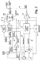
- the source is driven by a stable voltage controlled oscillator (VCO) 24 which is modulated by a drive signal 23.
- the drive signal is produced by a modulation voltage waveform generator that is synchronised by a clock 22.
- the difference in frequency of each of the frequency steps F, produced by the changing voltage of the drive is known as the FSK step size.
- a typical drive signal 23, in which four steps are present, is shown in Figure 3 of the accompanying drawings and this voltage signal is applied to the VCO.
- the source in turn sends out a narrow beam of microwave radiation to the front of the vehicle.
- the detected echo signal will also be a FSK signal with the four steps. Its strength will depend on the size of the vehicle, how reflective the vehicle is and also how far from the detector it is.
- the drive signal and the echo signal may be combined to extract the Doppler signal 25.
- the apparatus To determine the velocity and the distance the apparatus passes the Doppler signal 25 through an analogue to digital converter (A/D) 26.
- A/D analogue to digital converter
- the output of the A/D 26 is then fed to a digital signal processor (DSP) 27 together with a reference signal from the clock 21.
- DSP 27 generates a target velocity signal 28 which changes over time as the velocity changes and a distance signal 29.
- the target velocity signal 28 passes to an integrator 30 which integrates the velocity over time to determine a first change-in-distance over time value 31. This is then compared with the change in distance estimated "directly” using the distance output 29 of the DSP 27. The ratio of the "direct" estimate to the integrated estimate is used to form an error correction coefficient 32. Whenever distance is reported from the radar-which is produced in real time using the direct output signal 29 based on the FSK phase shift, the correction is applied so as to keep the reported distance accurate.
- the increased accuracy is achieved because the velocity measurement 28 is not affected by temperature to the same extent as the direct distance measurement 29. It is known that the main error in the direct distance measurement is the effects of temperature on the microwave components, and in particular the VCO 24.
- the Doppler based velocity measurement is dependent on the base frequency of the VCO which is controlled by a ceramic resonator.
- a heater 33 is provided within the VCO module and a temperature sensor 34 is provided which measures the temperature of the VCO module.
- the output of the temperature sensor 34 is passed to a heater controller 35 and the controller applies a voltage to the heater 33 until the measured temperature is within a target range.
- the output of the temperature sensor 33 is passed to the heater controlled it is corrected by subtracting a compensation value that is dependent upon the error correction coefficient 32 applied to the reported distance values.
- the correction of the temperature value ensures that drift of the temperature sensor with age is compensated for.
- the output from the temperature sensor is no longer assumed to be correct, and it is possible to compensate for changes in the temperature sensor's characteristics over time. Also, since the heater 33 will do its best to keep the temperature of the VCO 24 in the ideal range the magnitude of the correction that must be applied to the "direct" distance measurements will tend towards an ideal unitary value over time.
Landscapes
- Engineering & Computer Science (AREA)
- Radar, Positioning & Navigation (AREA)
- Remote Sensing (AREA)
- Computer Networks & Wireless Communication (AREA)
- Physics & Mathematics (AREA)
- General Physics & Mathematics (AREA)
- Radar Systems Or Details Thereof (AREA)
Claims (7)
- Radarbasierte Distanzmessvorrichtung, aufweisend:eine Mikrowellenschaltung, die einen Frequenzgenerator (24) aufweist, der ein Mikrowellenfrequenzsignal erzeugt, dessen Frequenz in einem Umfang moduliert wird, der von einem Modulationssignal bestimmt wird, welches an den Frequenzgenerator (24) angelegt wird,einen Temperatursensor (34), der eine Temperaturmessung von mindestens einem Teil der Mikrowellenschaltung ermittelt, und einen Frequenzregler, der dafür ausgelegt ist, die Frequenz, die vom Frequenzgenerator erzeugt wird, zu regulieren, wobei die Frequenzregulierungseinrichtung eine Heizung (33) aufweist, die dafür ausgelegt ist, den Frequenzgenerator (24) in einem Umfang zu erwärmen, der vom Wert des kompensierten Temperatursignals abhängt, dadurch gekennzeichnet, dass:die Vorrichtung eine Kompensierungseinrichtung aufweist zum Kompensieren von Fehlern in der Ausgabe des Temperatursensors (34), um unter Verwendung von Informationen, die vom Treibersignal (23) und einem Echosignal, das von einem Mikrowellendetektor (12) erfasst wird, ein kompensiertes Temperatursignal zu erzeugen;die Frequenzregulierungseinrichtung dafür ausgelegt ist, das kompensierte Temperatursignal zu empfangen und die Frequenz des vom Frequenzgenerator (24) erzeugten Signals zu regulieren, wodurch die Auswirkung von Änderungen der Temperatur des Frequenzgenerators (24) zumindest teilweise korrigiert wird,die Vorrichtung eine erste Verarbeitungseinrichtung (27) aufweist, die dafür ausgelegt ist, durch Messen der Doppler-Verschiebung zwischen dem Treibersignal (23) und einem Echosignal, das von einem Objekt zurückgeworfen wird, die relative Geschwindigkeit der Vorrichtung und des Ziels zu bestimmen;die Vorrichtung eine zweite Verarbeitungseinrichtung (27) aufweist, die dafür ausgelegt ist, durch Vergleichen der Phasenverschiebung zwischen Regionen auf jeder Seite des Frequenzsprungs des Treibersignals (23) und entsprechenden Regionen, die in einem vom Ziel zurückgeworfenen und vom Detektor erfassten Echosignal vorhanden sind, den Abstand eines Zieles von der Vorrichtung zu bestimmen; unddie Vorrichtung eine dritte Verarbeitungseinrichtung aufweist, die die Geschwindigkeit zwischen zwei verschiedenen Zeitpunkten integriert und daraus einen ersten Distanzveränderungswert bestimmt, der Hinweise gibt auf die Änderung der Distanz zwischen der Radarvorrichtung und dem Ursprung eines Echos zwischen diesen beiden Zeitpunkten.
- Radarvorrichtung nach Anspruch 1, bei der die Frequenzmodulierungseinrichtung das Modulierungssignal (23), das den Frequenzgenerator (24) angelegt wird, gemäß dem Wert des kompensierten Temperatursignals moduliert.
- Vorrichtung nach Anspruch 1 oder Anspruch 2, eine vierte Verarbeitungsvorrichtung aufweisend, die einen zweiten Distanzveränderungswert unter Verwendung der direkt erhaltenen Abstandsmessungen ermittelt, die zu diesen beiden Zeitpunkten genommen werden.
- Vorrichtung nach Anspruch 3, bei der die ersten, zweiten, dritten und vierten Verarbeitungseinrichtungen Teil einer einzigen integrierten Schaltung sind.
- Vorrichtung nach Anspruch 3, bei der die Vorrichtung einen Prozessor und einen Speicher aufweist, der Programmbefehle speichert, die bewirken, dass der Prozessor die Funktionen der ersten, zweiten, dritten und vierten Verarbeitungseinrichtungen ausführt.
- Vorrichtung nach Anspruch 3, 4 oder 5, die ferner eine Vergleichseinrichtung aufweist, die dafür ausgelegt ist, die ersten und zweiten Distanzänderungswerte zu vergleichen, um einen Fehlerwert zu erzeugen und um den Fehlerwert in die Kompensierungseinrichtung einzugeben, die dafür ausgelegt ist, das vom Temperatursensor (34) ausgegebene Temperatursignal in einem Umfang zu kompensieren, der von der Größe und dem Vorzeichen des Fehlerwerts abhängt.
- Vorrichtung nach Anspruch 4, die dafür ausgelegt ist, durch Kombinieren des Messwerts mit dem Fehlerwert, der vom Komparator erzeugt wird, einen protokollierten Abstandswert zu erzeugen, wann immer ein Abstandsmesswert von der ersten Verarbeitungseinrichtung erzeugt wird.
Applications Claiming Priority (3)
| Application Number | Priority Date | Filing Date | Title |
|---|---|---|---|
| GBGB0229515.2A GB0229515D0 (en) | 2002-12-19 | 2002-12-19 | Improvements in radar apparatus |
| GB0229515 | 2002-12-19 | ||
| PCT/GB2003/005553 WO2004057370A1 (en) | 2002-12-19 | 2003-12-18 | Temperature compensation improvements in radar apparatus |
Publications (2)
| Publication Number | Publication Date |
|---|---|
| EP1579242A1 EP1579242A1 (de) | 2005-09-28 |
| EP1579242B1 true EP1579242B1 (de) | 2013-07-03 |
Family
ID=9949926
Family Applications (1)
| Application Number | Title | Priority Date | Filing Date |
|---|---|---|---|
| EP03768019.6A Expired - Lifetime EP1579242B1 (de) | 2002-12-19 | 2003-12-18 | Verbesserung der temperaturkompensation in einem radargerät |
Country Status (7)
| Country | Link |
|---|---|
| US (1) | US7209074B2 (de) |
| EP (1) | EP1579242B1 (de) |
| JP (1) | JP4680600B2 (de) |
| AU (1) | AU2003292441A1 (de) |
| ES (1) | ES2426494T3 (de) |
| GB (1) | GB0229515D0 (de) |
| WO (1) | WO2004057370A1 (de) |
Families Citing this family (9)
| Publication number | Priority date | Publication date | Assignee | Title |
|---|---|---|---|---|
| GB0229515D0 (en) * | 2002-12-19 | 2003-01-22 | Trw Ltd | Improvements in radar apparatus |
| JP2010008273A (ja) * | 2008-06-27 | 2010-01-14 | Maspro Denkoh Corp | ミリ波撮像装置 |
| US8378879B2 (en) * | 2009-06-18 | 2013-02-19 | The Johns Hopkins University | Apparatus and methods for remote detection of physiological changes |
| US8196756B2 (en) | 2010-04-02 | 2012-06-12 | NanOasis | Asymmetric nanotube containing membranes |
| DE102011051971A1 (de) * | 2011-07-20 | 2013-01-24 | Hella Kgaa Hueck & Co. | Verfahren zur Bestimmung zumindest eines Parameters zur Korrelation zweier Objekte |
| DE102011055693A1 (de) * | 2011-11-24 | 2013-05-29 | Hella Kgaa Hueck & Co. | Radargerät und Verfahren zur Erkennung eines Ausfalls eines Empfangskanals eines Radargerätes |
| WO2014210506A2 (en) * | 2013-06-28 | 2014-12-31 | Associated Universities, Inc. | Randomized surface reflector |
| CN107765239A (zh) * | 2016-08-22 | 2018-03-06 | 邹谋炎 | 一种经济型短距测距雷达的设计和实现方法 |
| CN112363145A (zh) * | 2020-11-09 | 2021-02-12 | 浙江光珀智能科技有限公司 | 一种车载激光雷达温度补偿系统及方法 |
Family Cites Families (22)
| Publication number | Priority date | Publication date | Assignee | Title |
|---|---|---|---|---|
| JPS5574222A (en) * | 1978-11-30 | 1980-06-04 | Nec Corp | Temperature compensation circuit for crystal oscillator |
| US4454483A (en) * | 1982-03-25 | 1984-06-12 | Cubic Corporation | Temperature compensation of an oscillator by fractional cycle synthesis |
| FR2545669B1 (fr) * | 1983-05-03 | 1985-08-09 | France Etat Armement | Oscillateur a quartz compense en temperature |
| DE3322942C2 (de) * | 1983-06-25 | 1986-03-20 | Kernforschungsanlage Jülich GmbH, 5170 Jülich | Schaltung zur Messung der magnetischen Induktion mit einer Hall-Feldsonde |
| CH684441A5 (de) * | 1991-03-19 | 1994-09-15 | Mettler Toledo Ag | Elektromechanische Waage mit Saitenschwinger. |
| GB9107476D0 (en) * | 1991-04-09 | 1991-05-22 | Peek Traffic Ltd | Improvements in vehicle detection systems |
| US5237332A (en) * | 1992-02-25 | 1993-08-17 | Hughes Aircraft Company | Receiver distortion correction circuit and method |
| JP3342333B2 (ja) | 1997-01-08 | 2002-11-05 | 本田技研工業株式会社 | 電圧制御発振装置およびfmcwレーダ装置 |
| IL120119A0 (en) * | 1997-01-31 | 1997-04-15 | Binder Yehuda | Method and system for calibrating a crystal oscillator |
| DE19857040C2 (de) * | 1998-12-10 | 2000-12-21 | Siemens Ag | Verfahren zur Detekton und Korrektur von Nichtlinearitäten hochfrequenter, spannungsgesteuerter Oszillatoren |
| US6121919A (en) * | 1999-07-23 | 2000-09-19 | Eaton-Vorad Technologies, L.L.C. | Method and apparatus for range correction in a radar system |
| US6140976A (en) * | 1999-09-07 | 2000-10-31 | Motorola, Inc. | Method and apparatus for mitigating array antenna performance degradation caused by element failure |
| CA2341316A1 (en) * | 2000-03-17 | 2001-09-17 | Samir Kuliev | Digital indirectly compensated crystal oscillators |
| AU2001284953A1 (en) * | 2000-08-16 | 2002-02-25 | Raytheon Company | Safe distance algorithm for adaptive cruise control |
| AU2001288273A1 (en) * | 2000-08-16 | 2002-02-25 | Raytheon Company | Video amplifier for a radar receiver |
| US6577269B2 (en) * | 2000-08-16 | 2003-06-10 | Raytheon Company | Radar detection method and apparatus |
| JP3473577B2 (ja) | 2000-12-19 | 2003-12-08 | 日本電気株式会社 | レーダー装置 |
| JP4857466B2 (ja) * | 2001-01-18 | 2012-01-18 | 株式会社デンソー | 時間測定装置及び距離測定装置 |
| US6587072B1 (en) * | 2002-03-22 | 2003-07-01 | M/A-Com, Inc. | Pulse radar detection system |
| DE10229334B4 (de) * | 2002-06-29 | 2010-09-23 | Robert Bosch Gmbh | Verfahren und Vorrichtung zur Kalibrierung von Sensoren im Kraftfahrzeug mittels eines Kalibrierobjekts mit Triple-Spiegel als Bezugsmerkmal |
| GB0228731D0 (en) * | 2002-12-10 | 2003-01-15 | Trw Ltd | Frequency shift keying radar with ambiguity detection |
| GB0229515D0 (en) * | 2002-12-19 | 2003-01-22 | Trw Ltd | Improvements in radar apparatus |
-
2002
- 2002-12-19 GB GBGB0229515.2A patent/GB0229515D0/en not_active Ceased
-
2003
- 2003-12-18 JP JP2004561644A patent/JP4680600B2/ja not_active Expired - Lifetime
- 2003-12-18 ES ES03768019T patent/ES2426494T3/es not_active Expired - Lifetime
- 2003-12-18 EP EP03768019.6A patent/EP1579242B1/de not_active Expired - Lifetime
- 2003-12-18 WO PCT/GB2003/005553 patent/WO2004057370A1/en not_active Ceased
- 2003-12-18 AU AU2003292441A patent/AU2003292441A1/en not_active Abandoned
-
2005
- 2005-06-17 US US11/155,932 patent/US7209074B2/en not_active Expired - Lifetime
Also Published As
| Publication number | Publication date |
|---|---|
| AU2003292441A1 (en) | 2004-07-14 |
| US7209074B2 (en) | 2007-04-24 |
| JP2006510894A (ja) | 2006-03-30 |
| JP4680600B2 (ja) | 2011-05-11 |
| EP1579242A1 (de) | 2005-09-28 |
| WO2004057370A1 (en) | 2004-07-08 |
| GB0229515D0 (en) | 2003-01-22 |
| ES2426494T3 (es) | 2013-10-23 |
| US20060007037A1 (en) | 2006-01-12 |
Similar Documents
| Publication | Publication Date | Title |
|---|---|---|
| US4942561A (en) | Delay time measuring device | |
| US6100540A (en) | Laser displacement measurement system | |
| JP3622969B2 (ja) | 距離、速度、加速度を測定することができるレーザ・センサ | |
| US6864833B2 (en) | Time-base generator with self-compensating control loop | |
| EP1579242B1 (de) | Verbesserung der temperaturkompensation in einem radargerät | |
| JP4651251B2 (ja) | レーダレベルゲージの周波数安定化 | |
| EP3088914B1 (de) | Abstandsmessvorrichtung, elektronische vorrichtung, abstandsmessverfahren und abstandsmessprogramm | |
| EP2264481A1 (de) | Verfahren und Vorrichtung zum Erzeugen eines entfernungsaufgelösten Bildes | |
| KR940006316A (ko) | 파장측정장치 및 이를 탑재한 레지어장치 | |
| CN101201400A (zh) | 距离感测装置中校正非理想中频信号的方法和装置 | |
| EP0990887A2 (de) | Mikrowellen-Densitometer | |
| US4488813A (en) | Reflectivity compensating system for fiber optic sensor employing dual probes at a fixed gap differential | |
| US6420998B2 (en) | Method of detecting and correcting non-linearities in a microwave radar system | |
| JP2002539650A (ja) | 高周波電圧制御型発振器の非線形性の検出および補正方法 | |
| JP2006510894A5 (de) | ||
| US5614716A (en) | Alternating current method and apparatus for ambient temperature compensation for modulated energy sensors | |
| GB2519417A (en) | Radar apparatus and method | |
| JP7738277B2 (ja) | 対象物の距離および/または速度を計測する装置および方法 | |
| JP3879966B2 (ja) | 周波数変調レーダ、及び、レーダの周波数変調方法 | |
| US11188032B2 (en) | Molecular clock with delay compensation | |
| JP2853350B2 (ja) | レーザ測距装置 | |
| GB2547551A (en) | An electronic circuit | |
| EP1324072B1 (de) | Entfernungsmessgerät | |
| WO2021148390A1 (en) | Cancel a voltage dependent phase error of a time of flight imaging device | |
| JPS6396582A (ja) | マイクロ波レベル計 |
Legal Events
| Date | Code | Title | Description |
|---|---|---|---|
| PUAI | Public reference made under article 153(3) epc to a published international application that has entered the european phase |
Free format text: ORIGINAL CODE: 0009012 |
|
| 17P | Request for examination filed |
Effective date: 20050714 |
|
| AK | Designated contracting states |
Kind code of ref document: A1 Designated state(s): AT BE BG CH CY CZ DE DK EE ES FI FR GB GR HU IE IT LI LU MC NL PT RO SE SI SK TR |
|
| AX | Request for extension of the european patent |
Extension state: AL LT LV MK |
|
| DAX | Request for extension of the european patent (deleted) | ||
| RBV | Designated contracting states (corrected) |
Designated state(s): DE ES FR GB IT |
|
| 17Q | First examination report despatched |
Effective date: 20080424 |
|
| REG | Reference to a national code |
Ref country code: DE Ref legal event code: R079 Ref document number: 60344416 Country of ref document: DE Free format text: PREVIOUS MAIN CLASS: G01S0013930000 Ipc: G01S0007350000 |
|
| GRAP | Despatch of communication of intention to grant a patent |
Free format text: ORIGINAL CODE: EPIDOSNIGR1 |
|
| RIC1 | Information provided on ipc code assigned before grant |
Ipc: G01S 13/58 20060101ALI20130314BHEP Ipc: G01S 7/35 20060101AFI20130314BHEP Ipc: G01S 7/40 20060101ALI20130314BHEP |
|
| INTG | Intention to grant announced |
Effective date: 20130402 |
|
| GRAS | Grant fee paid |
Free format text: ORIGINAL CODE: EPIDOSNIGR3 |
|
| GRAA | (expected) grant |
Free format text: ORIGINAL CODE: 0009210 |
|
| AK | Designated contracting states |
Kind code of ref document: B1 Designated state(s): DE ES FR GB IT |
|
| REG | Reference to a national code |
Ref country code: GB Ref legal event code: FG4D |
|
| REG | Reference to a national code |
Ref country code: DE Ref legal event code: R096 Ref document number: 60344416 Country of ref document: DE Effective date: 20130829 |
|
| REG | Reference to a national code |
Ref country code: GB Ref legal event code: 732E Free format text: REGISTERED BETWEEN 20130815 AND 20130821 |
|
| REG | Reference to a national code |
Ref country code: ES Ref legal event code: FG2A Ref document number: 2426494 Country of ref document: ES Kind code of ref document: T3 Effective date: 20131023 |
|
| PLBE | No opposition filed within time limit |
Free format text: ORIGINAL CODE: 0009261 |
|
| STAA | Information on the status of an ep patent application or granted ep patent |
Free format text: STATUS: NO OPPOSITION FILED WITHIN TIME LIMIT |
|
| 26N | No opposition filed |
Effective date: 20140404 |
|
| REG | Reference to a national code |
Ref country code: DE Ref legal event code: R097 Ref document number: 60344416 Country of ref document: DE Effective date: 20140404 |
|
| REG | Reference to a national code |
Ref country code: FR Ref legal event code: PLFP Year of fee payment: 13 |
|
| REG | Reference to a national code |
Ref country code: FR Ref legal event code: PLFP Year of fee payment: 14 |
|
| PG25 | Lapsed in a contracting state [announced via postgrant information from national office to epo] |
Ref country code: IT Free format text: LAPSE BECAUSE OF NON-PAYMENT OF DUE FEES Effective date: 20151218 |
|
| PG25 | Lapsed in a contracting state [announced via postgrant information from national office to epo] |
Ref country code: IT Free format text: LAPSE BECAUSE OF NON-PAYMENT OF DUE FEES Effective date: 20151218 |
|
| PGRI | Patent reinstated in contracting state [announced from national office to epo] |
Ref country code: IT Effective date: 20170710 |
|
| REG | Reference to a national code |
Ref country code: FR Ref legal event code: PLFP Year of fee payment: 15 |
|
| PGFP | Annual fee paid to national office [announced via postgrant information from national office to epo] |
Ref country code: ES Payment date: 20180102 Year of fee payment: 15 |
|
| PGFP | Annual fee paid to national office [announced via postgrant information from national office to epo] |
Ref country code: IT Payment date: 20171221 Year of fee payment: 15 |
|
| PG25 | Lapsed in a contracting state [announced via postgrant information from national office to epo] |
Ref country code: IT Free format text: LAPSE BECAUSE OF NON-PAYMENT OF DUE FEES Effective date: 20181218 |
|
| REG | Reference to a national code |
Ref country code: ES Ref legal event code: FD2A Effective date: 20200204 |
|
| PGFP | Annual fee paid to national office [announced via postgrant information from national office to epo] |
Ref country code: FR Payment date: 20191226 Year of fee payment: 17 |
|
| PG25 | Lapsed in a contracting state [announced via postgrant information from national office to epo] |
Ref country code: ES Free format text: LAPSE BECAUSE OF NON-PAYMENT OF DUE FEES Effective date: 20181219 |
|
| PGFP | Annual fee paid to national office [announced via postgrant information from national office to epo] |
Ref country code: GB Payment date: 20200102 Year of fee payment: 17 Ref country code: DE Payment date: 20191231 Year of fee payment: 17 |
|
| REG | Reference to a national code |
Ref country code: DE Ref legal event code: R119 Ref document number: 60344416 Country of ref document: DE |
|
| GBPC | Gb: european patent ceased through non-payment of renewal fee |
Effective date: 20201218 |
|
| PG25 | Lapsed in a contracting state [announced via postgrant information from national office to epo] |
Ref country code: FR Free format text: LAPSE BECAUSE OF NON-PAYMENT OF DUE FEES Effective date: 20201231 |
|
| PG25 | Lapsed in a contracting state [announced via postgrant information from national office to epo] |
Ref country code: DE Free format text: LAPSE BECAUSE OF NON-PAYMENT OF DUE FEES Effective date: 20210701 Ref country code: GB Free format text: LAPSE BECAUSE OF NON-PAYMENT OF DUE FEES Effective date: 20201218 |