EP1579130B1 - Kolbenpumpsystem - Google Patents
Kolbenpumpsystem Download PDFInfo
- Publication number
- EP1579130B1 EP1579130B1 EP03789097A EP03789097A EP1579130B1 EP 1579130 B1 EP1579130 B1 EP 1579130B1 EP 03789097 A EP03789097 A EP 03789097A EP 03789097 A EP03789097 A EP 03789097A EP 1579130 B1 EP1579130 B1 EP 1579130B1
- Authority
- EP
- European Patent Office
- Prior art keywords
- piston
- pump system
- piston pump
- liquid
- pumping
- Prior art date
- Legal status (The legal status is an assumption and is not a legal conclusion. Google has not performed a legal analysis and makes no representation as to the accuracy of the status listed.)
- Expired - Lifetime
Links
- 239000007788 liquid Substances 0.000 claims description 58
- 238000005086 pumping Methods 0.000 claims description 41
- 239000007789 gas Substances 0.000 claims description 21
- 238000007906 compression Methods 0.000 claims description 10
- 230000006835 compression Effects 0.000 claims description 10
- 230000001225 therapeutic effect Effects 0.000 claims description 8
- 229920001296 polysiloxane Polymers 0.000 claims description 5
- IJGRMHOSHXDMSA-UHFFFAOYSA-N Atomic nitrogen Chemical compound N#N IJGRMHOSHXDMSA-UHFFFAOYSA-N 0.000 claims description 2
- 238000001802 infusion Methods 0.000 claims description 2
- 239000007922 nasal spray Substances 0.000 claims description 2
- 239000007921 spray Substances 0.000 claims description 2
- 241001631457 Cannula Species 0.000 claims 1
- 229940097496 nasal spray Drugs 0.000 claims 1
- 238000013022 venting Methods 0.000 claims 1
- 239000003814 drug Substances 0.000 description 11
- 229940079593 drug Drugs 0.000 description 11
- 239000003566 sealing material Substances 0.000 description 10
- 238000007789 sealing Methods 0.000 description 9
- 239000004480 active ingredient Substances 0.000 description 7
- 230000003068 static effect Effects 0.000 description 7
- 239000012530 fluid Substances 0.000 description 6
- 210000003491 skin Anatomy 0.000 description 5
- 239000002904 solvent Substances 0.000 description 5
- 230000035699 permeability Effects 0.000 description 4
- QVGXLLKOCUKJST-UHFFFAOYSA-N atomic oxygen Chemical compound [O] QVGXLLKOCUKJST-UHFFFAOYSA-N 0.000 description 3
- 230000008859 change Effects 0.000 description 3
- 229920001971 elastomer Polymers 0.000 description 3
- 239000000463 material Substances 0.000 description 3
- 239000001301 oxygen Substances 0.000 description 3
- 229910052760 oxygen Inorganic materials 0.000 description 3
- 230000035515 penetration Effects 0.000 description 3
- 239000000126 substance Substances 0.000 description 3
- 238000012546 transfer Methods 0.000 description 3
- LFQSCWFLJHTTHZ-UHFFFAOYSA-N Ethanol Chemical compound CCO LFQSCWFLJHTTHZ-UHFFFAOYSA-N 0.000 description 2
- 229920000459 Nitrile rubber Polymers 0.000 description 2
- 238000002485 combustion reaction Methods 0.000 description 2
- 230000008878 coupling Effects 0.000 description 2
- 238000010168 coupling process Methods 0.000 description 2
- 238000005859 coupling reaction Methods 0.000 description 2
- 238000012377 drug delivery Methods 0.000 description 2
- 230000000694 effects Effects 0.000 description 2
- 239000000806 elastomer Substances 0.000 description 2
- NBVXSUQYWXRMNV-UHFFFAOYSA-N fluoromethane Chemical compound FC NBVXSUQYWXRMNV-UHFFFAOYSA-N 0.000 description 2
- 230000036541 health Effects 0.000 description 2
- 230000003647 oxidation Effects 0.000 description 2
- 238000007254 oxidation reaction Methods 0.000 description 2
- 239000008194 pharmaceutical composition Substances 0.000 description 2
- 239000000825 pharmaceutical preparation Substances 0.000 description 2
- 239000004814 polyurethane Substances 0.000 description 2
- 238000009516 primary packaging Methods 0.000 description 2
- 229920002379 silicone rubber Polymers 0.000 description 2
- NLHHRLWOUZZQLW-UHFFFAOYSA-N Acrylonitrile Chemical compound C=CC#N NLHHRLWOUZZQLW-UHFFFAOYSA-N 0.000 description 1
- BRLQWZUYTZBJKN-UHFFFAOYSA-N Epichlorohydrin Chemical compound ClCC1CO1 BRLQWZUYTZBJKN-UHFFFAOYSA-N 0.000 description 1
- XUIMIQQOPSSXEZ-UHFFFAOYSA-N Silicon Chemical compound [Si] XUIMIQQOPSSXEZ-UHFFFAOYSA-N 0.000 description 1
- 230000001154 acute effect Effects 0.000 description 1
- 150000001298 alcohols Chemical class 0.000 description 1
- 125000000484 butyl group Chemical group [H]C([*])([H])C([H])([H])C([H])([H])C([H])([H])[H] 0.000 description 1
- 229920005549 butyl rubber Polymers 0.000 description 1
- 239000003795 chemical substances by application Substances 0.000 description 1
- 239000008139 complexing agent Substances 0.000 description 1
- 239000000470 constituent Substances 0.000 description 1
- 229920001577 copolymer Polymers 0.000 description 1
- 238000009792 diffusion process Methods 0.000 description 1
- 238000007599 discharging Methods 0.000 description 1
- 239000013583 drug formulation Substances 0.000 description 1
- 238000005516 engineering process Methods 0.000 description 1
- 229920005561 epichlorohydrin homopolymer Polymers 0.000 description 1
- 210000002615 epidermis Anatomy 0.000 description 1
- HQQADJVZYDDRJT-UHFFFAOYSA-N ethene;prop-1-ene Chemical group C=C.CC=C HQQADJVZYDDRJT-UHFFFAOYSA-N 0.000 description 1
- 238000009472 formulation Methods 0.000 description 1
- 239000004519 grease Substances 0.000 description 1
- 230000001771 impaired effect Effects 0.000 description 1
- 239000012535 impurity Substances 0.000 description 1
- 238000010348 incorporation Methods 0.000 description 1
- 238000009434 installation Methods 0.000 description 1
- 230000016507 interphase Effects 0.000 description 1
- 238000001990 intravenous administration Methods 0.000 description 1
- 239000012669 liquid formulation Substances 0.000 description 1
- 230000007774 longterm Effects 0.000 description 1
- 238000012423 maintenance Methods 0.000 description 1
- 230000007246 mechanism Effects 0.000 description 1
- 239000012528 membrane Substances 0.000 description 1
- 238000000034 method Methods 0.000 description 1
- 238000002156 mixing Methods 0.000 description 1
- 239000000203 mixture Substances 0.000 description 1
- 150000002825 nitriles Chemical class 0.000 description 1
- 239000005022 packaging material Substances 0.000 description 1
- 239000002245 particle Substances 0.000 description 1
- 239000011505 plaster Substances 0.000 description 1
- 239000004033 plastic Substances 0.000 description 1
- 229920003023 plastic Polymers 0.000 description 1
- 239000004014 plasticizer Substances 0.000 description 1
- 229920000642 polymer Polymers 0.000 description 1
- -1 polytetrafluoroethylene Polymers 0.000 description 1
- 229920001343 polytetrafluoroethylene Polymers 0.000 description 1
- 239000004810 polytetrafluoroethylene Substances 0.000 description 1
- 229920002635 polyurethane Polymers 0.000 description 1
- 230000008569 process Effects 0.000 description 1
- 239000005060 rubber Substances 0.000 description 1
- 229910052710 silicon Inorganic materials 0.000 description 1
- 239000010703 silicon Substances 0.000 description 1
- 239000011877 solvent mixture Substances 0.000 description 1
- 210000000434 stratum corneum Anatomy 0.000 description 1
- 239000012815 thermoplastic material Substances 0.000 description 1
- 238000009423 ventilation Methods 0.000 description 1
- XLYOFNOQVPJJNP-UHFFFAOYSA-N water Substances O XLYOFNOQVPJJNP-UHFFFAOYSA-N 0.000 description 1
Images


Classifications
-
- A—HUMAN NECESSITIES
- A61—MEDICAL OR VETERINARY SCIENCE; HYGIENE
- A61M—DEVICES FOR INTRODUCING MEDIA INTO, OR ONTO, THE BODY; DEVICES FOR TRANSDUCING BODY MEDIA OR FOR TAKING MEDIA FROM THE BODY; DEVICES FOR PRODUCING OR ENDING SLEEP OR STUPOR
- A61M5/00—Devices for bringing media into the body in a subcutaneous, intra-vascular or intramuscular way; Accessories therefor, e.g. filling or cleaning devices, arm-rests
- A61M5/14—Infusion devices, e.g. infusing by gravity; Blood infusion; Accessories therefor
- A61M5/142—Pressure infusion, e.g. using pumps
- A61M5/14244—Pressure infusion, e.g. using pumps adapted to be carried by the patient, e.g. portable on the body
- A61M5/14248—Pressure infusion, e.g. using pumps adapted to be carried by the patient, e.g. portable on the body of the skin patch type
-
- A—HUMAN NECESSITIES
- A61—MEDICAL OR VETERINARY SCIENCE; HYGIENE
- A61M—DEVICES FOR INTRODUCING MEDIA INTO, OR ONTO, THE BODY; DEVICES FOR TRANSDUCING BODY MEDIA OR FOR TAKING MEDIA FROM THE BODY; DEVICES FOR PRODUCING OR ENDING SLEEP OR STUPOR
- A61M37/00—Other apparatus for introducing media into the body; Percutany, i.e. introducing medicines into the body by diffusion through the skin
-
- A—HUMAN NECESSITIES
- A61—MEDICAL OR VETERINARY SCIENCE; HYGIENE
- A61M—DEVICES FOR INTRODUCING MEDIA INTO, OR ONTO, THE BODY; DEVICES FOR TRANSDUCING BODY MEDIA OR FOR TAKING MEDIA FROM THE BODY; DEVICES FOR PRODUCING OR ENDING SLEEP OR STUPOR
- A61M37/00—Other apparatus for introducing media into the body; Percutany, i.e. introducing medicines into the body by diffusion through the skin
- A61M37/0015—Other apparatus for introducing media into the body; Percutany, i.e. introducing medicines into the body by diffusion through the skin by using microneedles
-
- A—HUMAN NECESSITIES
- A61—MEDICAL OR VETERINARY SCIENCE; HYGIENE
- A61M—DEVICES FOR INTRODUCING MEDIA INTO, OR ONTO, THE BODY; DEVICES FOR TRANSDUCING BODY MEDIA OR FOR TAKING MEDIA FROM THE BODY; DEVICES FOR PRODUCING OR ENDING SLEEP OR STUPOR
- A61M5/00—Devices for bringing media into the body in a subcutaneous, intra-vascular or intramuscular way; Accessories therefor, e.g. filling or cleaning devices, arm-rests
- A61M5/14—Infusion devices, e.g. infusing by gravity; Blood infusion; Accessories therefor
- A61M5/142—Pressure infusion, e.g. using pumps
- A61M5/145—Pressure infusion, e.g. using pumps using pressurised reservoirs, e.g. pressurised by means of pistons
- A61M5/1452—Pressure infusion, e.g. using pumps using pressurised reservoirs, e.g. pressurised by means of pistons pressurised by means of pistons
-
- F—MECHANICAL ENGINEERING; LIGHTING; HEATING; WEAPONS; BLASTING
- F04—POSITIVE - DISPLACEMENT MACHINES FOR LIQUIDS; PUMPS FOR LIQUIDS OR ELASTIC FLUIDS
- F04B—POSITIVE-DISPLACEMENT MACHINES FOR LIQUIDS; PUMPS
- F04B19/00—Machines or pumps having pertinent characteristics not provided for in, or of interest apart from, groups F04B1/00 - F04B17/00
- F04B19/006—Micropumps
-
- F—MECHANICAL ENGINEERING; LIGHTING; HEATING; WEAPONS; BLASTING
- F04—POSITIVE - DISPLACEMENT MACHINES FOR LIQUIDS; PUMPS FOR LIQUIDS OR ELASTIC FLUIDS
- F04B—POSITIVE-DISPLACEMENT MACHINES FOR LIQUIDS; PUMPS
- F04B53/00—Component parts, details or accessories not provided for in, or of interest apart from, groups F04B1/00 - F04B23/00 or F04B39/00 - F04B47/00
- F04B53/14—Pistons, piston-rods or piston-rod connections
-
- F—MECHANICAL ENGINEERING; LIGHTING; HEATING; WEAPONS; BLASTING
- F04—POSITIVE - DISPLACEMENT MACHINES FOR LIQUIDS; PUMPS FOR LIQUIDS OR ELASTIC FLUIDS
- F04B—POSITIVE-DISPLACEMENT MACHINES FOR LIQUIDS; PUMPS
- F04B53/00—Component parts, details or accessories not provided for in, or of interest apart from, groups F04B1/00 - F04B23/00 or F04B39/00 - F04B47/00
- F04B53/16—Casings; Cylinders; Cylinder liners or heads; Fluid connections
- F04B53/162—Adaptations of cylinders
- F04B53/164—Stoffing boxes
-
- F—MECHANICAL ENGINEERING; LIGHTING; HEATING; WEAPONS; BLASTING
- F16—ENGINEERING ELEMENTS AND UNITS; GENERAL MEASURES FOR PRODUCING AND MAINTAINING EFFECTIVE FUNCTIONING OF MACHINES OR INSTALLATIONS; THERMAL INSULATION IN GENERAL
- F16J—PISTONS; CYLINDERS; SEALINGS
- F16J15/00—Sealings
- F16J15/16—Sealings between relatively-moving surfaces
- F16J15/32—Sealings between relatively-moving surfaces with elastic sealings, e.g. O-rings
-
- A—HUMAN NECESSITIES
- A61—MEDICAL OR VETERINARY SCIENCE; HYGIENE
- A61M—DEVICES FOR INTRODUCING MEDIA INTO, OR ONTO, THE BODY; DEVICES FOR TRANSDUCING BODY MEDIA OR FOR TAKING MEDIA FROM THE BODY; DEVICES FOR PRODUCING OR ENDING SLEEP OR STUPOR
- A61M5/00—Devices for bringing media into the body in a subcutaneous, intra-vascular or intramuscular way; Accessories therefor, e.g. filling or cleaning devices, arm-rests
- A61M5/14—Infusion devices, e.g. infusing by gravity; Blood infusion; Accessories therefor
- A61M5/142—Pressure infusion, e.g. using pumps
- A61M2005/14208—Pressure infusion, e.g. using pumps with a programmable infusion control system, characterised by the infusion program
-
- A—HUMAN NECESSITIES
- A61—MEDICAL OR VETERINARY SCIENCE; HYGIENE
- A61M—DEVICES FOR INTRODUCING MEDIA INTO, OR ONTO, THE BODY; DEVICES FOR TRANSDUCING BODY MEDIA OR FOR TAKING MEDIA FROM THE BODY; DEVICES FOR PRODUCING OR ENDING SLEEP OR STUPOR
- A61M37/00—Other apparatus for introducing media into the body; Percutany, i.e. introducing medicines into the body by diffusion through the skin
- A61M37/0015—Other apparatus for introducing media into the body; Percutany, i.e. introducing medicines into the body by diffusion through the skin by using microneedles
- A61M2037/0023—Drug applicators using microneedles
-
- A—HUMAN NECESSITIES
- A61—MEDICAL OR VETERINARY SCIENCE; HYGIENE
- A61M—DEVICES FOR INTRODUCING MEDIA INTO, OR ONTO, THE BODY; DEVICES FOR TRANSDUCING BODY MEDIA OR FOR TAKING MEDIA FROM THE BODY; DEVICES FOR PRODUCING OR ENDING SLEEP OR STUPOR
- A61M37/00—Other apparatus for introducing media into the body; Percutany, i.e. introducing medicines into the body by diffusion through the skin
- A61M37/0015—Other apparatus for introducing media into the body; Percutany, i.e. introducing medicines into the body by diffusion through the skin by using microneedles
- A61M2037/003—Other apparatus for introducing media into the body; Percutany, i.e. introducing medicines into the body by diffusion through the skin by using microneedles having a lumen
-
- A—HUMAN NECESSITIES
- A61—MEDICAL OR VETERINARY SCIENCE; HYGIENE
- A61M—DEVICES FOR INTRODUCING MEDIA INTO, OR ONTO, THE BODY; DEVICES FOR TRANSDUCING BODY MEDIA OR FOR TAKING MEDIA FROM THE BODY; DEVICES FOR PRODUCING OR ENDING SLEEP OR STUPOR
- A61M2205/00—General characteristics of the apparatus
- A61M2205/02—General characteristics of the apparatus characterised by a particular materials
- A61M2205/0244—Micromachined materials, e.g. made from silicon wafers, microelectromechanical systems [MEMS] or comprising nanotechnology
-
- A—HUMAN NECESSITIES
- A61—MEDICAL OR VETERINARY SCIENCE; HYGIENE
- A61M—DEVICES FOR INTRODUCING MEDIA INTO, OR ONTO, THE BODY; DEVICES FOR TRANSDUCING BODY MEDIA OR FOR TAKING MEDIA FROM THE BODY; DEVICES FOR PRODUCING OR ENDING SLEEP OR STUPOR
- A61M2205/00—General characteristics of the apparatus
- A61M2205/02—General characteristics of the apparatus characterised by a particular materials
- A61M2205/0272—Electro-active or magneto-active materials
- A61M2205/0294—Piezoelectric materials
-
- A—HUMAN NECESSITIES
- A61—MEDICAL OR VETERINARY SCIENCE; HYGIENE
- A61M—DEVICES FOR INTRODUCING MEDIA INTO, OR ONTO, THE BODY; DEVICES FOR TRANSDUCING BODY MEDIA OR FOR TAKING MEDIA FROM THE BODY; DEVICES FOR PRODUCING OR ENDING SLEEP OR STUPOR
- A61M5/00—Devices for bringing media into the body in a subcutaneous, intra-vascular or intramuscular way; Accessories therefor, e.g. filling or cleaning devices, arm-rests
- A61M5/14—Infusion devices, e.g. infusing by gravity; Blood infusion; Accessories therefor
- A61M5/142—Pressure infusion, e.g. using pumps
- A61M5/14212—Pumping with an aspiration and an expulsion action
- A61M5/14216—Reciprocating piston type
Definitions
- the present invention relates to a piston pump system for substantially gas-free metering and / or pumping over predetermined amounts of liquids, preferably pharmaceutical liquids with oxidation-sensitive components.
- the system is used as a mini or micropump or component thereof in medical devices such as transdermal therapeutic systems.
- the gas thus penetrated into the metering chamber can falsify the metering process and thus change the amount of liquid to be delivered.
- the fluid to be delivered per se should not contain large amounts of gas so as not to endanger the health of the patient.
- the WO 01/89612 A1 describes a piston pump system for dispensing small amounts of liquid of 0.01 ml to 2 ml, in which a piston movable in a cylinder is moved by combustion as in an internal combustion engine and thereby a small amount of active ingredient via an attached pin, which communicates with a chamber stands, drives out.
- the US 4,246,833 discloses a piston pump system for high pressure applications in which an O-ring seal of, for example, silicone accomplishes a sealing fitting of the piston to a cylinder.
- the EP 0361260 A2 discloses a piston pump system with a drip change mechanism in which the cylinder is centrally formed to form a ring upon which an O-ring seal rests.
- the DE 19921951 A1 discloses a piezo-piston pump, wherein the piston has both a circumferential ring seal to the cylinder, as well as a front-side ring seal to a pressure chamber.
- O-ring seals are arranged analogously to well-known piston rings in grooves in or on the outer surface of the piston.
- the grooves are circumferential recesses in the piston outer surface.
- transdermal therapeutic systems as described in the EP 0840634 disclosed.
- Such systems consist essentially of a reservoir for the drug and at least one - typically several - provided with capillary openings micro spines that rotate with the reservoir in connection that the drug in the form of a drug-containing solution from the reservoir passes into the micro spines.
- the transcorneal system When the transcorneal system is placed on the skin, the stratum corneum and optionally the epidermis are penetrated by the micro spines, so that there is direct access to the innervated skin layer.
- the drug from the reservoir through the capillary openings of the micro spines can reach into vascularized portions of the skin to be taken there via the capillary circulatory system in the bloodstream.
- the active ingredient is usually in the form of a solution to ensure proper transport through the capillary holes of the micro-spines of the transcorneal system.
- the transport of the drug can be "active", for example, by a stored in the reservoir overpressure, electrostatic or capillary forces, or a system integrated pump.
- active system is used in the EP 0840634B1 describe.
- Another object is to provide a medical device pumping system which prevents the pharmaceutical fluid from being mixed with oxygen, air or other gas by metering or pumping.
- Another object is to overcome the known from the prior art disadvantages of pumping system in medical devices.
- the present invention now relates to a piston pumping system which can be used as or in a small pump, e.g. a mini or micropump, can be used in medical devices for direct application of pharmaceutical formulations.
- the device according to the invention is preferably used in medical devices which may require or require a pump for dispensing liquids.
- the invention can be applied in any other not necessarily limited to medical devices piston pump system in which it can be used advantageously.
- the invention is not limited to mini pumps or micropumps, but can also be applied to larger pumping systems.
- the term medical device liquid application devices such as transdermal therapeutic systems with active drug delivery, devices for the intravenous administration of liquid formulations in very small quantities, atomizers of liquids such as inhalers, in particular propellant-free inhalers, needleless injectors, eye sprays, etc . Understood.
- Such medical devices also serve, in part, as primary packaging for pharmaceutical preparations, or may be considered as such, since the pharmaceutical preparation is initially stored in these devices before the device is used on or for the patient. Therefore, the term also includes medical devices that serve as primary packaging.
- a piston pumping system which, using food or drug suitable sealing materials, improves the sealing of the piston in the pumping system from the inward diffusion of air or other gases from the external environment into the liquid to be filled or metered and thus the ingress of air or other Reduced gases in this liquid.
- the pumping system according to the invention overcomes the abovementioned disadvantages of the conventional pumping systems.
- a pumping and metering system suitable for the invention may consist of a chamber provided with a liquid inlet and a liquid outlet, a piston being connected to the chamber such that liquid is stroked along its longitudinal axis by a movement of the piston Storage system can be sucked in a predetermined amount and then discharged from there via the liquid outlet optionally under pressure.
- the storage system can rest between two strokes.
- the storage system is designed as a flexible container that coincides with the removal of liquid.
- very small size systems i. a metering or pumping chamber with a volume in the microliter range and corresponding cross sections of the supply and Abpublishedwege and a storage system, it may then come in the chamber in the resting phase to a static negative pressure or static vacuum. That the negative pressure in the storage system is passed on to the pumping chamber.
- the pumping system according to the invention is designed both for a dynamic high-pressure load, as well as for a dynamic and / or static negative pressure load.
- pressures of more than 1 bar are understood.
- the system is designed for a pressure of up to 600 bar, more preferably up to 250 bar. This pressure can be maintained up to about 10 seconds, preferably up to 5 seconds, more preferably up to 2 seconds.
- Underpressure is understood to mean a pressure difference of preferably less than 0.5 bar, preferably less than 100 mbar, and more preferably less than 50 mbar.
- a static negative pressure is understood to mean that it is maintained for a period of more than 5 minutes, preferably more than 1 hour, preferably more than 10 hours, and most preferably about 24 hours.
- the above-mentioned chamber is also referred to as pumping chamber or measuring chamber.
- the chamber preferably has a filling volume of 1 microliter up to 1 ml, more preferably 1 microliter up to 500 microliters, particularly preferably from 5 microliters up to 100 microliters. Most preferred are volumes from 5 microliters up to 30 microliters.
- the liquid inlet or the delivery system connected to the liquid inlet, which leads the liquid from the storage system into the chamber, is preferably formed by tubes or hoses.
- the cross-section of the tube opening is preferably less than 1 mm, more preferably less than 0.5 mm.
- the delivery system preferably has a non-return valve, which prevents a return of the sucked liquid in the reservoir.
- the system of liquid inlet and / or the delivery system is referred to in the context of the present invention description as an intake system.
- the intake system can be integrated in the pump piston.
- the pump piston is a hollow piston.
- the hollow inner region of the piston then constitutes the inlet for the liquid from the storage system into the chamber or is connected to such an inlet.
- the intake system includes a check valve, preferably as an integral part of the piston.
- the liquid outlet, or the fluid discharge system connected to the liquid discharge, which supplies the liquid from the pumping or measuring chamber to its further destination, may - but need not - have such a check valve.
- the liquid outlet in each case has a check valve when the filling system is such that a return of the liquid pressed out of the metering chamber from the destination via the liquid outlet back into the pumping or metering chamber is possible or undesirable.
- the situation is comparable when there is a risk that air can be drawn from the outside into the pumping chamber via the discharge system. Even then, a check valve makes sense.
- the system fluid inlet and / or the said discharge system is also referred to in the context of the present invention description as only a discharge system.
- the movable piston protruding into the pumping chamber is guided in a cylindrical bore of a fixed element, for example a block or a wall.
- a fixed element for example a block or a wall.
- Such a block or wall may be an independent element in the pumping system or is an integral part of the chamber.
- the piston can over a predetermined stroke movement are introduced into the chamber or pulled out of this. By this lifting movement, the chamber is filled and emptied.
- the dimensions of the piston and the chamber should be matched accordingly.
- the piston preferably has a length of 5 mm to 10 cm, preferably from 1 cm to 7.5 cm.
- the cross section of the piston is preferably 0.25 to 4 mm, more preferably 0.5 to 3 mm, and most preferably 0.75 to 2.25 mm.
- the stroke movement of the piston along its longitudinal axis preferably covers a length of 1 mm to 5 cm, in particular from 0.25 cm to 3 cm. More preferred are strokes of 0.5 cm to 2 cm.
- a seal on the piston regardless of its movement, seals the space between the piston and the chamber, preventing any liquid from escaping. That the piston is guided in the pumping system so that it can not break out of the cylindrical guide during normal operation and always fulfills its sealing effect.
- sealing material Special requirements are placed on the sealing material - as well as on all other materials of systems for filling pharmaceutical liquids. So they must be such that neither the pharmaceutical quality of the liquid is impaired, nor that it comes to impurities that endanger the health of the end user. These requirements also apply in particular to the sealing material, which is usually elastic polymers from which constituents can repeatedly escape during use which are undesirable in the liquids to be filled for the reasons stated above. In this context, the public discussion of plasticizers, etc. in packaging materials for food and the like is being discussed. pointed.
- the sealing systems for the reciprocating piston must be primarily selected so that they can not change the quality of the liquid. This criterion must be subordinated to the functional conditions.
- Such secondary properties of the sealing material include the density of the material and / or its permeation coefficient for air or other gases.
- the piston guide in the pump system is preferably guided over silicone seals, since silicone has the said food-grade or pharmaceutically acceptable properties.
- a disadvantage of this sealing material and other sealing materials suitable for food or drug legislation is that these materials have a relatively high permeation coefficient for air so that air and oxygen can diffuse into the liquid to be filled through the sealing material.
- Common sealing materials such as NBR or PU can not be used in all cases for pharmaceutical reasons.
- the seal is designed as an O-ring seal.
- O-ring is meant an annular seal, regardless of the shape of its cross section.
- Preferred are O-ring seals with a circular cross-section.
- the piston can be sealed by one or more O-rings.
- at least one seal in the guide tube of the piston is located in the vicinity of the entry point of the piston in the pumping chamber.
- the prior art provides for the installation of such O-rings for sealing the dynamically loaded piston rod a cross-sectional compression of 10% to about 15% before. As a result, a balanced ratio of wear and tightness is given.
- Silicone rubbers are considered to be completely unsuitable because they have particularly high gas permeabilities.
- the O-ring seal is guided with a radial and optionally axial compression of up to 30%, preferably up to 20%.
- radial compression is meant the compression which is exerted along the ring plane on the sealing ring.
- an O-ring seal with a gas permeation of 100 to 500 N * cm 3 * mm / (m 2 * h * bar) and a cord thickness of 0.3 to 3 mm, preferably 0.5 to 2 mm, is now more preferred 0.75 to 1.5 mm, which seals a reciprocating along its longitudinal axis reciprocating piston in a guide tube and is held in a groove, wherein the seal a radial and possibly axial compression of up to 30%, preferably until to 20% and has a Nutrachllgrad of 90 to 100%.
- Preferred sealing material is silicone.
- the pump according to the invention can be operated mechanically or electrically. Details can be found in the prior art. These embodiments may be electronically controlled, preferably via a microchip.
- the piston may e.g. be operated by coupling with a piezoelectric element.
- This coupling can be direct, via one or more lever arms or a membrane.
- the piston is moved directly from the piezoelectric element.
- the piezoelectric element itself in such a case is e.g. controlled via the microchip.
- the piston can also be operated via a spring, for example a helical spring, which is tensioned mechanically or electrically and is connected to the piston via a flange.
- a spring for example a helical spring, which is tensioned mechanically or electrically and is connected to the piston via a flange. Details may be the prior art for medical devices, in particular from the Transdermal therapeutic systems, nebulizers, propellant-free inhalers, needleless injectors, etc. are removed.
- Preferred solvents are water and pharmacologically acceptable alcohols, such as ethanol. Should it be necessary, solubilizers and complexing agents can be used to increase the solubility of the active ingredient in the solvent. Sensitive agents can be added to increase storage stability.
- the medical device comprises a reservoir for storing the active ingredient solution, a liquid-conducting connection between the reservoir and the pump according to the invention, and a liquid-conducting connection to at least one device which discharges the liquid.
- the latter may be a nozzle, a micro-spike, a micro-cutting edge along which the liquid is passed, a cannula or spout.
- Micro-cutting and micro-spikes are detailed in the EP 0840634 and there described in Figures 6, nozzle systems, the EP 1017469 be removed.
- Such nozzle systems may include a single nozzle opening or multiple nozzle openings.
- Such a nozzle may be a body having at least two or more through holes that are parallel to each other or inclined relative to each other. In the case of mutually inclined bores, the side with the acute angle forms the nozzle outlet side, the other side corresponding to the nozzle inlet side.
- preferably small volumes of liquids are metered from a storage system via the pumping and / or metering system into a pumping chamber and from there to the device discharging the liquid .
- Such systems include, for example transcomeal therapeutic systems (TTS, "patch” systems), nebulizers, especially pump systems in nasal sprays, inhalers, eye showers, infusion systems, needleless injectors, etc., provided that they meter and deliver propellant-free fluids for delivery to a patient.
- TTS transcomeal therapeutic systems
- nebulizers especially pump systems in nasal sprays, inhalers, eye showers, infusion systems, needleless injectors, etc., provided that they meter and deliver propellant-free fluids for delivery to a patient.
- Transcorneal therapeutic systems continuously or discontinuously transfer pharmaceutical formulations from a reservoir into a patient via the skin.
- the pumping system according to the invention for example, in a TTS like it from the EP 0840634 , which is hereby incorporated by reference, is described incorporated.
- Such a system can consist of a storage system, into which projects the pump piston of the pumping system according to the invention, which is preferably designed as a hollow piston with integrated check valve.
- the hollow piston discharges into the metering chamber, from which a discharge system leads into one or several spike-like extensions.
- the discharge system which consists of at least one tube preferably a check valve (or more check valves) on.
- FIG. 1 shows such a pumping system with a piston 1 of 1.5 mm diameter.
- the piston opens into the pumping chamber 5.
- the piston is guided in a guide tube 2 and sealed by an O-ring seal 3 in a groove 4.
- a silicone elastomer is used as the sealing material.
- the piston leads into the pumping and measuring chamber 5.
- the storage chamber bears the reference numeral 6b.
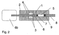
- FIG. 2 shows the system after FIG. 1 in which the delivery tube 6 is integrated in the piston 1.
- FIG. 3 shows a transdermal therapeutic system with the pump according to the invention.
- the figure shows a section through a transcomeal system 10 with a drug reservoir 11, which is closed at its top by a bellows 13.
- the drug solution 14 which on the lower side of the drug reservoir via a system 15 after FIG. 2 to the arranged on the bottom of the housing micro spines with capillary openings 12 is conveyed to the outside.
- the housing side parts 16 and the housing bottom together with the micro spines form a structural unit, preferably made of a thermoplastic material.
- the lid of the housing contains the power supply in the form of a battery 17 for operating the pumping system and an electronic control 18, for example a microchip. Ventilation 19 allows the bellows to accommodate this reduced volume as drug delivery through the micro-spikes is delivered.
- the micro spines Prior to use of the transcorneal system, the micro spines are protected by a spiked guard 20, for example in the form of a cap.
- the micro spines may include microvalves 21 as they are FIG. 4 are shown.
Landscapes
- Engineering & Computer Science (AREA)
- Health & Medical Sciences (AREA)
- General Engineering & Computer Science (AREA)
- Mechanical Engineering (AREA)
- General Health & Medical Sciences (AREA)
- Animal Behavior & Ethology (AREA)
- Anesthesiology (AREA)
- Biomedical Technology (AREA)
- Heart & Thoracic Surgery (AREA)
- Hematology (AREA)
- Life Sciences & Earth Sciences (AREA)
- Veterinary Medicine (AREA)
- Public Health (AREA)
- Dermatology (AREA)
- Vascular Medicine (AREA)
- Medical Informatics (AREA)
- Infusion, Injection, And Reservoir Apparatuses (AREA)
- Sealing Devices (AREA)
- Details Of Reciprocating Pumps (AREA)
Description
- Die vorliegende Erfindung betrifft ein Kolbenpumpsystem zum im Wesentlichen gasfreien Abmessen und/oder Umpumpen vorbestimmter Mengen an Flüssigkeiten, bevorzugt pharmazeutischen Flüssigkeiten mit oxidationsempfindlichen Bestandteilen. Bevorzugt wird das System als Mini- oder Mikropumpe oder Bestandteil einer solchen in Medizingeräten wie beispielsweise transdermalen therapeutischen Systemen eingesetzt.
- In Medizingeräten zum Ausbringen von pharmazeutischen Flüssigkeiten ist es oft notwendig definierte Volumina der Flüssigkeit mittels eines Pumpsystems aus einem Vorratssystem abzumessen und zum Ort des Ausbringens zu überführen. Je kleiner und handlicher das Medizingerät ist, um so kleiner muss die Pumpe beschaffen sein. Bei herkömmlichen Abfüllsystemen und/oder Pump-betriebenen Transportsystemen kann es vorkommen, dass die Flüssigkeit während der Überführung von einem Raum in einen anderen mittels der Pumpe mit dem Gas aus der Umgebung in Kontakt kommt oder sich dieses Gas mit der Flüssigkeit vermischt. Ein solches Durchdringen von Gas und Flüssigkeit ist nicht immer erwünscht. Dieser Effekt ist in verschiedenen Fällen nicht tolerabel. So gibt es z.B. Flüssigkeiten mit oxidationsempfindlichen Substanzen und das Vermischen mit Sauerstoff z.B. aus der Luft beeinträchtigt maßgeblich die pharmazeutische Qualität des Formulierung. In anderen Fällen kann das so in die Abmessskammer eingedrungene Gas den Abmessvorgang verfälschen und damit die auszubringende Menge der Flüssigkeit verändern. In anderen Fällen, bei denen die Flüssigkeit parenteral appliziert wird, z.B. intravenös, darf die auszubringende Flüssigkeit per se keine größeren Mengen an Gas enthalten, um die Gesundheit des Patienten nicht zu gefährden.
- Dieses Problem der Gaseindringung tritt insbesondere bei Kolbenpumpsystemen auf, bei denen die abzufüllende Flüssigkeit aus einem Vorratssystem über einen sich hubartig hin- und herbewegende Kolben in eine Abmesskammer überführt wird und von dort aus dem weiteren Bestimmungsort zugeführt wird. In solchen Systemen bewegt sich der Pumpkolben in einer Führungsröhre und ist gegenüber dieser abgedichtet. Die Dichtung soll dann verhindern, dass es zu einem Austreten der Flüssigkeit aus dem Abfüllraum oder zu einem Eindringen von Gas in den Abfüllraum kommen kann.
- Die
WO 01/89612 A1 - Die
US 4,246,833 offenbart ein Kolbenpumpensystem für Hochdruckanwendungen, bei dem eine O-Ringdichtung aus beispielsweise Silikon ein dichtendes Fitting des Kolbens zu einem Zylinder bewerkstelligt. - Die
EP 0361260 A2 offenbart ein Kolbenpumpensystem mit einem Mechanismus zum Verändern eines Nachtropfens, bei dem der Zylinder mittig eingeformt ist, um einen Ring zu bilden, auf dem eine O-Ringdichtung aufliegt. - Die
DE 19921951 A1 offenbart eine Piezo-Kolbenpumpe, wobei der Kolben sowohl eine Umfangs-Ringdichtung zum Zylinder, als auch eine stirnseitige Ringdichtung zu einem Druckraum aufweist. - Bei der
WO 01/89612 A1 US 4,246,833 , derEP 0361260 A2 und derDE 19921951 A1 sind die O-Ringdichtungen analog zu allgemein bekannten Kolbenringen in Nuten in oder auf der Außenfläche des Kolbens angeordnet. Die Nuten sind dabei umlaufende Ausnehmungen in der Kolbenaußenfläche. - Für die Erfindung geeignete Medizingeräte werden z.B. transdermale therapeutische Systeme wie sie in der
EP 0840634 offenbart. Solche Systeme bestehen im Wesentlichen aus einem Reservoir für das Arzneimittel und mindestens einem - typischerweise mehreren - mit kapillaren Öffnungen versehenen Mikrostacheln, die so mit dem Reservoir in Verbindung srehen, daß das Arzneimittel in Form einer wirkstoffhaltigen Lösung aus dem Reservoir in die Mikrostacheln gelangt. Bei Aufsetzen des transcornealen Systems auf die Haut wird das Stratum corneum und gegebenenfalls die Epidermis von den Mikrostacheln durchdrungen, so daß ein direkter Zugang zur innervierten Hautschicht gegeben ist. Damit kann das Arzneimittel aus dem Reservoir durch die kapillaren Öffnungen der Mikrostacheln bis in vaskularisierte Abschnitte der Haut gelangen, um dort über das kapillare Kreislaufsystem in den Blutkreislauf aufgenommen zu werden. In den Systemen liegt der Wirkstoff üblicherweise in Form einer Lösung vor, um einen einwandfreien Transport durch die kapillaren Öffnungen der Mikrostacheln des transcornealen Systems zu gewährleisten. - Der Transport des Medikaments kann "aktiv", beispielsweise durch einen im Reservoir gespeicherten Überdruck, elektrostatische oder kapillare Kräfte, oder eine im System integrierte Pumpe erfolgen. Ein solches aktives System wird in der
EP 0840634B1 beschreiben. - Es ist Aufgabe der vorliegenden Erfindung ein kolbenbetriebenes Pumpsystem bereit zu stellen, welches gewährleistet, dass beim Abmessen und/oder Umpumpen von Flüssigkeiten mittels eines Kolbenpumpsystems im wesentlichen keine Gas entlang dem Kolben von Außen in die Abfüll- oder Pumpkammer gelangen kann.
- Eine weitere Aufgabe besteht darin, ein Pumpsystem für Medizingeräte zu schaffen, welches verhindert, dass durch das Abmessen oder Umpumpen die pharmazeutische Flüssigkeit mit Sauerstoff, Luft oder einem anderen Gas vermischt werden.
- Eine weitere Aufgabe besteht darin, die aus dem Stand der Technik bekannten Nachteile von Pumpsystem in Medizingeräten zu überwinden.
- Die vorliegende Erfindung betrifft nun ein Kolbenpumpsystem, das als oder in einer kleinen Pumpe, z.B. einer Mini- oder Mikropumpe, in Medizingeräten zu direkten Applikation von pharmazeutischen Formulierungen verwendet werden kann. Bevorzugt wird die erfindungsgemäße Vorrichtung in Medizingeräten, die zum Ausbringen von Flüssigkeiten eine Pumpe benötigen oder benötigen können, verwendet. Die Erfindung kann jedoch in jedem anderen nicht zwingend nur auf Medizingeräte beschränkten Kolbenpumpsystem angewendet werden, in dem sie vorteilhaft eingesetzt werden kann. Die Erfindung ist auch nicht auf Minipumpen oder Mikropumpen beschränkt, sondern kann auch auf größere Pumpsystem übertragen werden.
- Im Rahmen der vorliegenden Erfindung werden bevorzugt unter dem Begriff Medizingerät, Applikationsapparaturen für Flüssigkeiten wie transdermalen therapeutische Systeme mit aktivem Wirkstofftransport, Geräte für die intravenöse Verabreichungen von flüssigen Formulierungen in Kleinstmengen, Zerstäuber von Flüssigkeiten, wie Inhalatoren, insbesondere treibgasfreie Inhalatoren, nadellose Injektoren, Augensprays etc. verstanden. Solche Medizingeräte dienen zum Teil auch als Primärpackmittel für pharmazeutische Zubereitungen oder können als solche betrachtet werden, da die pharmazeutische Zubereitung in diesen Geräten zunächst gelagert wird, bevor das Gerät am oder für den Patienten zum Einsatz kommt. Daher umfasst der Begriff ebenfalls Medizingeräte, die als Primärpackmittel dienen.
- Erfindungsgemäß wird ein Kolbenpumpsystem bereitgestellt, welches unter Verwendung von Lebensmittel- oder Arzneimittel-technisch geeigneten Dichtungsmaterialien die Abdichtung des Kolbens im Pumpsystem gegenüber dem Eindiffundieren von Luft oder anderen Gasen aus der Außenumgebung in die abzufüllende oder abzumessende Flüssigkeit verbessert und damit das Eindringen von Luft oder anderen Gasen in diese Flüssigkeit reduziert. Durch das erfindungsgemäße Pumpsystem werden die oben genannten Nachteile der gängigen Pumpsysteme überwunden.
- Ein für die Erfindung geeignetes Pump- und Abmesssystem kann aus einer Kammer bestehen, die mit einem Flüssigkeitseinlass und einem Flüssigkeitsauslass versehen ist, wobei ein Kolben so mit der Kammer verbunden ist, dass durch entlang seiner Längsachse hubartige Bewegung des Kolbens Flüssigkeit über den Flüssigkeitseinlass aus einem Vorratssystem in einer vorbestimmten Menge angesaugt werden kann und dann von dort aus über den Flüssigkeitsauslass gegebenenfalls unter Druck ausgebracht wird.
- Zwischen zwei Hubbewegungen kann das System ruhen. In manchen Fällen ist das Vorratssystem als flexibler Behälter ausgebildet, der mit der Entnahme von Flüssigkeit zusammenfällt. In solchen Vorratssystems, insbesondere, Systemen mit sehr kleinen Abmessungen, d.h. eine Abmess- oder Pumpkammer mit einem Volumen im Mikroliter-Bereich und entsprechenden Querschnitten der Zu- und Abführwege und einem Vorratssystem, kann es dann in der Kammer in der Ruhephase zu einem statischen Unterdruck bzw. statischen Vakuum kommen. D.h. der Unterdruck im Vorratssystem wird an die Pumpkammer weitergegeben.
- Das erfindungsgemäße Pumpsystem ist dementsprechend sowohl für eine dynamische Hochdruckbelastung ausgelegt, als auch für eine dynamische und/oder statische Unterdruckbelastung. Unter Hochdruck werden Drücke von mehr als 1 bar verstanden. Bevorzugt ist das System auf einen Druck von bis zu 600 bar ausgelegt, besonders bevorzugt bis zu 250 bar. Dieser Druck kann bis zu ca. 10 Sekunden, bevorzugt bis zu 5 Sekunden, stärker bevorzugt bis zu 2 Sekunden aufrecht erhalten werden.
- Unter Unterdruck wird eine Druckdifferenz von bevorzugt weniger als 0,5 bar, bevorzugt weniger als 100 mbar und stärker bevorzugt von weniger als 50 mbar verstanden. Unter einem statischen Unterdruck wird verstanden, dass dieser über einen Zeitraum von mehr als 5 Minuten, bevorzugt mehr als 1 Stunde, bevorzugt mehr als 10 Stunden und am stärksten bevorzugt von ca. 24 Stunden aufrecht erhalten wird.
- Im Rahmen der vorliegenden Beschreibung wird die oben erwähnte Kammer auch als Pumpkammer oder Abmesskammer bezeichnet. Bevorzugt weist die Kammer ein Füllvolumen von 1 Mikroliter bis zu 1 ml auf, stärker bevorzugt 1 Mikroliter bis zu 500 Mikrolitern, insbesondere bevorzugt von 5 Mikrolitern bis zu 100 Mikrolitern. Am stärksten bevorzugt sind Volumina von 5 Mikrolitern bis zu 30 Mikrolitern.
- Der Flüssigkeitseinlass bzw. das mit dem Flüssigkeitseinlass verbundene Zuliefersystem, welches die Flüssigkeit aus dem Vorratssystem in die Kammer führt, wird bevorzugt von Röhren oder Schläuchen gebildet. Der Querschnitt der Rohröffnung beträgt bevorzugt weniger als 1 mm, stärker bevorzugt weniger als 0,5 mm.
- Das Zuliefersystem weist bevorzugt ein Rückschlagventil auf, welches ein Rücklaufen der angesaugten Flüssigkeit in den Vorratsbehälter verhindert. Das System aus Flüssigkeitseinlass und/oder das Zuliefersystem wird im Rahmen der vorliegenden Erfindungsbeschreibung auch als Ansaugsystem bezeichnet.
- Das Ansaugsystem kann gegebenenfalls in dem Pumpkolben integriert werden. In diesem Fall handelt es sich bei dem Pumpkolben um einen Hohlkolben. Der hohle innere Bereich des Kolbens stellt dann den Zulauf für die Flüssigkeit aus dem Vorratssystem in die Kammer dar oder ist mit einem solchen Zulauf verbunden. In diesem Fall enthält das Ansaugsystem ein Rückschlagventil, bevorzugt als integraler Bestandteil des Kolbens.
- Der Flüssigkeitsauslass, bzw. das mit dem Flüssigkeitsauslass verbundene Abführsystem für die Flüssigkeit, welches die Flüssigkeit aus der Pump- oder Messkammer seinem weiteren Bestimmungsort zuführt, kann - muss aber nicht - ein solches Rückschlagventil aufweisen. Der Flüssigkeitsauslass weist in jedem Fall dann ein Rückschlagventil auf, wenn das Abfüllsystem dergestalt ist, dass ein Rücklaufen der aus der Abmesskammer herausgepressten Flüssigkeit vom Bestimmungsort über den Flüssigkeitsauslass zurück in die Pump- bzw. Abmesskammer möglich oder unerwünscht ist. Vergleichbar ist die Situation, wenn Gefahr besteht, dass über das Abführsystem Luft von außen in die Pumpkammer gezogen werden kann. Auch dann ist ein Rückschlagventil sinnvoll.
- Das System Flüssigkeitseinlass und/oder das besagte Abführsystem wird im Rahmen der vorliegenden Erfindungsbeschreibung auch als nur als Abführsystem bezeichnet.
- Der in die Pump- bzw. Abmesskammer ragende bewegliche Kolben wird in einer zylindrischen Bohrung eines festen Elements geführt, beispielsweise einem Block oder einer Wand. Ein solcher Block oder eine solche Wand kann in dem Pumpsystem ein eigenständiges Element sein oder ist integraler Bestandteil der Kammer. Der Kolben kann über eine vorbestimmte Hubbewegung in die Kammer eingeführt werden oder aus dieser herausgezogen werden. Durch diese Hubbewegung wird die Kammer gefüllt und geleert. Die Dimensionen des Kolbens und der Kammer sollten entsprechend aufeinander abgestimmt sein.
- Der Kolben weist bevorzugt eine Länge von 5 mm bis zu 10 cm auf, bevorzugt von 1 cm bis zu 7,5 cm.
- Der Querschnitt des Kolbens beträgt bevorzugt 0,25 bis 4 mm, stärker bevorzugt 0,5 bis 3 mm und am stärksten bevorzugt 0,75 bis 2,25 mm.
- Die Hubbewegung des Kolbens entlang seiner Längsachse überstreicht bevorzugt eine Länge von 1 mm bis zu 5 cm, insbesondere von 0,25 cm bis zu 3 cm. Stärker bevorzugt sind Hubbewegungen von 0,5 cm bis 2 cm.
- Eine Dichtung am Kolben dichtet unabhängig von dessen Bewegung den Raum zwischen dem Koben und der Kammer ab und verhindert so, dass Flüssigkeit austreten kann. D.h. der Kolben wird in dem Pumpsystem so geführt, dass er im Normalbetrieb nicht aus der zylindrischen Führung ausbrechen kann und die seine Dichtungswirkung stets erfüllt.
- An das Dichtungsmaterial - wie auch an alle anderen Materialien von Systemen zum Abfüllen von pharmazeutische Flüssigkeiten, sind besondere Anforderungen gestellt. So müssen sie derart beschaffen sein, dass weder die pharmazeutische Qualität der Flüssigkeit beeinträchtigt wird, noch das es zu Verunreinigungen kommt, die die Gesundheit des Endkonsumenten gefährden. Diese Anforderungen gelten insbesondere auch an das Dichtungsmaterial, das sich hierbei in der Regel um elastische Polymere handelt, aus denen während der Verwendung immer wieder Bestandteile austreten können, die in den abzufüllenden Flüssigkeiten aus den oben genannten Gründen unerwünscht sind. In diesem Zusammenhang wird auf die öffentliche Diskussion um Weichmacher etc. in Verpackungsmaterialien für Nahrungsmittel u.ä. hingewiesen.
- Daher müssen im Rahmen der erfindungsgemäßen Pumpe die Dichtungssysteme für den Hubkolben primär so ausgesucht werden, dass sie die Qualität der Flüssigkeit nicht verändern können. Diesem Kriterium müssen sich die funktionsbedingten Rahmenbedingungen unterordnen. Zu solchen sekundären Eigenschaften des Dichtungsmaterials gehören die Dichte des Materials und/oder deren Permeationskoeffizienten für Luft oder andere Gase. Erfindungsgemäß wird die Kolbenführung in dem Pumpsystem bevorzugt über Silikon-Dichtungen geführt, da Silikon die genannten lebensmittel-geeigneten bzw. pharmazeutisch akzeptablen Eigenschaften aufweist. Ein Nachteil dieses Dichtungsmaterials und bezüglich der Lebensmittel- oder Arzneimittel-gesetzlichen Bestimmungen geeigneten anderer Dichtungsmaterialien besteht allerdings darin, dass diese Materialien einen relativ hohen Permeationskoeffizienten für Luft aufweisen, so dass durch das Dichtungsmaterial Luft und Sauerstoff in die abzufüllende Flüssigkeit diffundieren kann. Gängige Dichtungsmaterialien wie zum Beispiel bei NBR oder PU können aus pharmazeutischen Gründen nicht in allen Fällen eingesetzt werden.
- Bevorzugt ist die Dichtung als O-Ringdichtung ausgeführt. Unter O-Ring wird eine ringförmige Dichtung verstanden, unabhängig von der Form ihres Querschnitts. Bevorzugt sind O-Ringdichtungen mit kreisrundem Querschnitt.
- Der Kolben kann durch einen oder mehrere O-Ringe abgedichtet werden. Bevorzugt befindet sich wenigstens eine Dichtung in der Führungsröhre des Kolbens in der Nähe des Eintrittsorts des Kolbens in die Pumpkammer.
- Der Stand der Technik sieht beim Einbau von derartigen O-Ringen zur Abdichtung der dynamisch belasteten Kolbenstange eine Querschnittsverpressungen von 10 % bis ca. 15 % vor. Dadurch sei ein ausgeglichenes Verhältnis von Verschleiß und Dichtheit gegeben.
- Es hat sich nun überraschend gezeigt, dass diese Einbauverhältnis in den erfindungsgemäßen Medizingeräten nicht zu einer ausreichenden Dichtigkeit für die statische Vakuumabdichtung führt.
- Für solche Abdichtungen werden Verpressungen von über 50 % und einem Nutfüllgrad von üblicherweise 80%, bei Vakuumabdichtung von bis zu 100% gelehrt (Wilhelm Schmitt, "Kunststoffe und Elastomere in der Dichtungstechnik", W.Kohlhammer GmbH 1987, Kapitel 2.1.4, Seite 228, Kapitel 2.2.1, Seite 231). Im Fall von statischen Vakuumdichtungen gelten nach dem zitierten Stand der Technik Verpressungsgrade von größer 50%, die Verwendung von Vakuumfett, eine Rauhtiefe von Nut und Gegenstelen von kleiner als 0,5 Mikrometer und eine sehr geringe Gaspermeabilität als zwingende Voraussetzungen. Um die geringe Gaspermeabilität zu gewährleisten sind folgende O-Ring-Basiselastomere bekannt: Butylkautschuk, Epichlorhydrin, Fluorcarbonkautschuk und Nitilkautschuk mit hohem Acrylnitirilgehalt.
- Als gänzlich ungeeignet werden Silikonkautschuke betrachtet, da sie besonders hohe Gaspermeabilitäten aufweisen.
- Die folgende Tabelle gibt einen Überblick über die Gaspermeabilitäten verschiedener Stoffe. Die Gaspermeation wird über den Gaspermeationskoeffizienten P verglichen [N*cm3*mm/(m2*h*bar)] für Stickstoff (N2):
P bei 20°C P bei 80°C Butyl 0,2 - 0,6 8-15 Epichlorhydrin Copolymer 0,5 - 4 10-40 Epichlorhydrin Homopolymer 0,04 1 - 5 Fluorcarbon 0,2 - 2 12 - 4ß Nitril 0,5 - 5 15 - 100 Ethylen-Propylen 2 - 10 40 - 100 Polytetrafluorethylen 1,5 - 5 5 - 30 Polyurethan 0,5 - 1,3 18 - 50 Silicon 100 - 500 500 - 1200 - Derartig hohe Verpressungen führen aber zu nicht akzeptablen Verschleiß und zu sehr hohen Reibungskräften bei dynamischer Belastung. Der Verscheiß gefährdet auf Dauer nicht nur das Einhalten der erfindungsgemäßen Aufgabe, sondern kann auch zu einer Belastung der Flüssigkeit in der Pumpkammer und damit der Wirkstoffformulierung mit abgeriebenen Partikeln führen, was aus pharmazeutischer Sicht nicht akzeptabel ist.
- Überraschend wurde nun gefunden, dass entgegen den Annahmen aus dem Stand der Technik das Problem der nicht ausreichend permeations- bzw. diffusionsdichten Abdichtung der O-Ringdichtung bei statischen Vakuumabdichtungen mit Dichtungen, die einen Gaspermeationskoeffizienten von 100 bis 500 N*cm3*mm/(m2*h*bar) aufweisen, dadurch gelöst werden kann, dass weder die Verpressung der Dichtung erhöht wird, noch dass die Dichtung gefettet werden muss, sondern dass allein der Ausfüllgrad der Dichtung in der sie haltenden Nut (Nutfüllgrad) optimal eingestellt wird.
- Erfindungsgemäß wird die O-Ringdichtung mit einer radialen und ggf. axialen Verpressung von bis zu 30%, bevorzugt bis zu 20% geführt. Unter radialer Verpressung wird die Verpressung verstanden die entlang der Ringebene auf den Dichtungsring ausgeübt wird.
- Erfindungsgemäß wird nun eine O-Ringdichtung mit einer Gaspermeation von 100 bis 500 N*cm3*mm/(m2*h*bar) und einer Schnurstärke von 0,3 bis 3 mm, bevorzugt 0,5 bis 2 mm, stärker bevorzugt 0,75 bis 1,5 mm vorgeschlagen, die einen sich entlang seiner Längsachse hin- und herbewegenden Hubkolben in einer Führungsröhre abdichtet und in einer Nut gehalten wird, wobei die Dichtung eine radiale und ggf. axiale Verpressung von bis zu 30%, bevorzugt bis zu 20% aufweist und einen Nutfüllgrad von 90 bis 100% aufweist.
- Unter einem Nutfüllgrand von 90% wir verstanden, dass das 90% des Volumens der Nut mit der Dichtung gefüllt sind.
- Bevorzugtes Dichtungsmaterial ist Silicon.
- Die erfindungsgemäße Pumpe kann mechanisch oder elektrisch betrieben werden. Einzelheiten können dem Stand der Technik entnommen werden. Diese Ausführungsformen können elektronisch gesteuert sein, bevorzugt über einen Mikrochip.
- Der Kolben kann z.B. durch Koppelung mit einem piezoelektrischen Element betrieben werden. Diese Koppelung kann direkt sein, über einen oder mehrere Hebelarme oder eine Membran. Bevorzugt wird der Kolben direkt von dem piezoelektrischen Element bewegt. Das piezoelektrischen Element selbst wird in einem solchen Fall z.B. über den Mikrochip angesteuert.
- Der Kolben kann auch über eine Feder, z.B. Schraubenfeder, betrieben werden, die mechanisch oder elektrisch gespannt wird und mit dem Kolben über einen Flansch verbunden ist. Einzelheiten können dem Stand der Technik für Medizingeräte, insbesondere aus den Bereichen transdermale therapeutische Systeme, Zerstäuber, treibgasfreie Inhalatoren, nadellose Injektoren etc. entnommen werden.
- Prinzipiell können mit den erfindungsgemäßen Medizingeräten und dem beschriebenen Pumpsystem alle physiologisch verträglichen Lösungsmittel oder Lösungsmittelgemische, in denen sich der Wirkstoff in ausreichender Menge löst, verwendet werden. Unter einer ausreichenden Menge werden solche Konzentrationen an Wirkstoff im Lösungsmittel verstanden, die es ermöglicht, eine therapeutisch wirksame Menge Wirkstoff applizieren zu können.
- Bevorzugte Lösungsmittel sind Wasser und pharmakologisch verträgliche Alkohole, wie Ethanol. Sollte es notwendig sein, können zur Erhöhung der Löslichkeit des Wirkstoffes im Lösungsmittel Lösungsvermittler und Komplexbildner verwendet werden. Empfindliche Wirkstoffe können zur Erhöhung der Lagerstabilität mit Zusätzen versehen werden.
- Das erfindungsgemäße Medizingerät enthält ein Reservoir zur Speicherung der Wirkstofflösung, eine flüssigkeitsleitende Verbindung zwischen dem Reservoir und der erfindungsgemäßen Pumpe, und eine flüssigkeitsleitende Verbindung zu wenigstens einer die Flüssigkeit ausbringenden Einrichtung. Letztere kann eine Düse, ein Mikrostachel, eine Mikroschneide sein, an der die Flüssigkeit entlang geführt wird, eine Kanüle oder ein Auslauf. Mikroschneiden und Mikrostacheln werden ausführlich in der
EP 0840634 und dort in den Figuren 6 beschrieben, Düsensysteme können derEP 1017469 entnommen werden. Solche Düsensysteme können eine einzige Düsenöffnung enthalten oder mehrere Düsenöffnungen. Eine solche Düse kann ein Körper sein mit wenigstens zwei oder mehr durchgehenden Bohrungen, die parallel zueinander verlaufen oder gegeneinander geneigt sind. Im Fall von gegeneinander geneigten Bohrungen, bildet die Seite mit dem spitzen Winkel die Düsenauslaßseite, die andere Seite entsprechend die Düseneinlaßseite. - Mit den erfindungsgemäßen Geräten werden bevorzugt geringe Volumina an Flüssigkeiten, z.B. weniger als 1 ml oder sogar weniger als 100 Mikrolitern, aus einem Vorratssystem über das Pump- und/oder Abmesssystem in eine Pumpkammer hinein abgemessen und von dort aus zu der die Flüssigkeit ausbringenden Einrichtung geführt . Solche Systeme umfassen z.B. transcomeale therapeutische Systeme (TTS, "Pflaster"-Systeme), Zerstäuber, insbesondere Pumpsysteme in Nasensprays, Inhalatoren, Augenduschen, Infusionssystem, nadellose Injektoren etc., vorausgesetzt, dass sie treibmittelfreie Flüssigkeiten abmessen und ausbringen, um sie einem Patienten zuzuführen.
- Transcorneale therapeutische Systeme überführen kontinuierlich oder diskontinuierlich pharmazeutische Formulierungen aus einem Vorratsbehälter über die Haut in einen Patienten. So kann das erfindungsgemäße Pumpsystem z.B. in ein TTS wie es von der
EP 0840634 , auf die hiermit ausdrücklich Bezug genommen wird, beschrieben ist, eingebaut werden. Ein solches System kann aus einem Vorratssystem bestehen, in dieses ragt der Pumpkolben des erfindungsgemäßen Pumpsystems, welcher bevorzugt als Hohlkolben mit integriertem Rückschlagventil ausgebildet ist. Der Hohlkolben mündet in die Abmesskammer von der aus ein Abführsystem in einen oder mehre stachelförmige Fortsätze führt. Dieser oder diese stachelförmige(n) Fortsatz (Fortsätze) sind ebenfalls hohl und so ausgebildet, dass sie - wenn das Pflastersystem gebrauchsfertig mit der Haut des Patienten verbunden ist - in das Corneum des Patienten einstechen und dort die Flüssigkeit hineingepumpt werden kann. In einem solchen System weist das Abführsystem, welches aus wenigsten einem Rohr besteht bevorzugt ein Rückschlagventil (oder mehrere Rückschlagventile) auf. - Bei einer Kolbenpumpe zur Dosierung von sehr kleinen Volumina ist, bei einem einzelnen Kolbenhub, eine Flüssigkeitsmenge von ca. 15 µL sehr präzise zu fördern. Dies muss auch bei der ersten Betätigung nach längerer Nichtbenutzung der Fall sein. Um dies sicherzustellen, darf während der Nichtbenutzung keine Luft in die Pumpe eintreten, da sonst die Dosierung nicht mehr in der gewünschten Genauigkeit erfolgen kann.
-
Figur 1 zeigt ein solches Pumpsystem mit einem Kolben 1 von 1,5 mm Durchmesser. Der Kolben mündet in der Pumpkammer 5. Der Kolben wird in einer Führungsröhre 2 geführt und über eine O-Ringdichtung 3 in einer Nut 4 abgedichtet. Der O-Ring weist zum Beispiel eine Schnurstärke von dl = 1,1 mm auf und es wird eine radiale Verpressung von ca. 20 % eingestellt. Dadurch ergibt sich eine Nuttiefe von t = 0,9 mm. Zum Einstellen des Nutfüllgrads wird eine Nutbreite b1 = 1,1 mm gewählt, so dass ein Nutfüllgrad von 95 % eingestellt wird. - Aus chemischen Gründen wird ein Silikonelastomer als Dichtungswerkstoff eingesetzt.
- Der Kolben führt in die Pump- und Abmesskammer 5. In die Kammer mündet eine Zufuhrröhre 6 mit einem Rückschlagventil 7, durch welche Flüssigkeit angesaugt wird.
- Aus der Kammer führt eine Abführröhre 8 mit dem Rückschlagventil 9 Flüssigkeit ab. Die Vorratskammer trägt das Bezugszeichen 6b.
-
Figur 2 zeigt das System nachFigur 1 , bei welchem die Zuführöhre 6 in dem Kolben 1 integriert ist. -
Figur 3 zeigt ein transdermales therapeutisches System mit der erfindungsgemäßen Pumpe. Die Figur zeigt einen Schnitt durch ein transcomeales System 10 mit einem Wirkstoffreservoir 11, das an seiner Oberseite durch einen Faltenbalg 13 abgeschlossen ist. In dem Wirkstoffreservoir befindet sich die Wirkstofflösung 14, die an der unteren Seite des Wirkstoffreservoirs über ein System 15 nachFigur 2 zu den an der Unterseite des Gehäuses angeordnete Mikrostacheln mit kapillaren Öffnungen 12 nach außen befördert wird. Die Gehäuseseitenteile 16 und die Gehäuseunterseite bilden zusammen mit den Mikrostacheln eine konstruktive Einheit, bevorzugt aus einen thermoplastischen Kunststoff. Der Deckel des Gehäuses enthält die Energieversorgung in Form einer Batterie 17 zum Betreiben des Pumpsystems sowie eine elektronische Steuerung 18, z.B. einen Mikrochip. Eine Belüftung 19 ermöglicht, daß der Faltenbalg bei der Abgabe von Wirkstofflösung durch die Mikrostacheln sich diesem verringerten Volumen anpassen kann. Vor dem Gebrauch des transcornealen Systems sind die Mikrostacheln durch einen Stachelschutz 20, beispielsweise in Form einer Kappe, geschützt. - Gegebenenfalls können die Mikrostacheln Mikroventile 21 beinhalten, wie sie
Figur 4 dargestellt sind.
Claims (18)
- Kolbenpumpsystem zur Dosierung pharmazeutischer Flüssigkeiten mit Pumpvolumen von 1 Mikroliter bis 1 ml bestehend aus einem in einer Führungsröhre (2) geführten Kolben (1), der entlang seiner Längsachse eine Hubbewegung ausführen kann, der in eine Pumpkammer (5) mündet, wobei die Pumpkammer (5) über eine flüssigkeitsleitende Verbindung mit Ventil (7) mit einem Vorratsgefäß (11) verbunden ist und von der Pumpkammer (5) eine flüssigkeitsleitende Verbindung zu einer Einrichtung (8) zum Ausbringen der Flüssigkeit führt, dadurch gekennzeichnet, dass die Führungsröhre (2) eine Nut (4) umfasst, in der eine O-Ringdichtung (3) angeordnet ist, die den Kolben (1) abdichtet und wobei die Dichtung einen Gaspermeationskoeffizienten von 100 bis 500 N*cm3*mm/(m2*h*bar) für Stickstoff (N2), eine radiale Verpressung von weniger als 30% aufweist und die Dichtung (3) die Nut (4) mit einem Nutfüllgrad von mehr als 90% füllt und wobei der Kolben (1) einen Querschnitt von 0,75 bis 2,25 mm aufweist.
- Kolbenpumpsystem nach Anspruch 1, dadurch gekennzeichnet, dass der Nutfüllgrad mehr als 95% beträgt.
- Kolbenpumpsystem nach Anspruch 1 oder 2, dadurch gekennzeichnet, dass das Ventil ein Rückschlagventil (7) ist.
- Kolbenpumpsystem nach einem der Ansprüche 1 bis 3, dadurch gekennzeichnet, dass in der Verbindung zu einer Einrichtung zum Ausbringen der Flüssigkeit ein Rückschlagventil (9) ausgebildet ist.
- Kolbenpumpsystem nach einem der Ansprüche 1 bis 4, dadurch gekennzeichnet, dass der Kolben (1) eine Länge von 5 mm bis zu 10 cm aufweist, bevorzugt von 1 cm bis zu 7,5 cm.
- Kolbenpumpsystem nach einem der Ansprüche 1 bis 5, dadurch gekennzeichnet, dass die Hubbewegung des Kolbens (1) entlang seiner Längsachse eine Länge von bis zu 1 mm bis zu 5 cm, bevorzugt von 0,25 cm bis zu 3 cm, stärker bevorzugt von 0,5 cm bis 2 cm überstreicht.
- Kolbenpumpsystem nach einem der Ansprüche 1 bis 6, dadurch gekennzeichnet, dass die O-Ringdichtung (3) aus Silikon besteht.
- Kolbenpumpsystem nach einem der Ansprüche 1 bis 7, dadurch gekennzeichnet, dass der Kolben (1) ein Hohlkolben ist, in dem die flüssigkeitsleitende Verbindung mit Ventil (7), welche die Pumpkammer (5) mit einem Vorratsgefäß (11) verbindet, integriert ist.
- Kolbenpumpsystem nach einem der Ansprüche 1 bis 8, dadurch gekennzeichnet, dass die Bewegung des Kolben (1) mechanisch gesteuert wird.
- Kolbenpumpsystem nach Anspruch 9, dadurch gekennzeichnet, dass der Kolben (1) über eine Schraubenfeder bewegt wird.
- Kolbenpumpsystem nach einem der Ansprüche 1 bis 8, dadurch gekennzeichnet, dass die Bewegung des Kolben elektronisch gesteuert wird.
- Kolbenpumpsystem nach Anspruch 11, dadurch gekennzeichnet, dass der Kolben mittels eines Mikrochip (18) gesteuert wird.
- Kolbenpumpsystem nach Anspruch 11 oder 12, dadurch gekennzeichnet, dass der Kolben mittels eines piezoelektrischen Elements bewegt wird.
- Kolbenpumpsystem nach einem der vorangehenden Ansprüche, dadurch gekennzeichnet, dass die Einrichtung zum Ausbringen der Flüssigkeit wenigstens eine Düse, wenigstens ein Mikrostachel, wenigstens eine Mikroschneide sein, an der die Flüssigkeit entlang geführt wird, wenigstens Kanülen und/oder wenigstens ein Auslauf ist.
- Kolbenpumpsystem nach einem der vorangehenden Ansprüche, dadurch gekennzeichnet, dass die Schnurstärke des O-Rings (3) 0,3 bis 3 mm beträgt, bevorzugt 0,5 bis 2 mm, stärker bevorzugt 0,75 bis 1,5 min.
- Medizingerät zum Ausbringen von pharmazeutischen Flüssigkeiten beinhaltend ein Kolbenpumpsystem nach einem der Ansprüche 1 bis 15.
- Medizingerät nach Anspruch 16, dadurch gekennzeichnet, dass das Medizingerät ein transdermal, therapeutisches System ist, welches neben dem Kolbenpumpsystem ein Vonatsgefäß aus wenigstens einem beweglichen Element oder mit einer Entlüftungsöffnung aufweist und wenigstens eine Mikrostachel oder Mikroschneide.
- Medizingerät nach Anspruch 16, dadurch gekennzeichnet, dass das Medizingerät ein Zerstäuber für Flüssigkeiten, ein Nasenspray, ein Augenspray, ein Inhalator, bevorzugt ein treibgasfreier Inhalator, ein nadelloser Injektor oder ein Infusionsgerät ist.
Priority Applications (1)
| Application Number | Priority Date | Filing Date | Title |
|---|---|---|---|
| EP03789097A EP1579130B1 (de) | 2002-12-06 | 2003-11-27 | Kolbenpumpsystem |
Applications Claiming Priority (4)
| Application Number | Priority Date | Filing Date | Title |
|---|---|---|---|
| EP02027243A EP1426662A1 (de) | 2002-12-06 | 2002-12-06 | Kolbenpumpsystem |
| EP02027243 | 2002-12-06 | ||
| EP03789097A EP1579130B1 (de) | 2002-12-06 | 2003-11-27 | Kolbenpumpsystem |
| PCT/EP2003/013368 WO2004053362A1 (de) | 2002-12-06 | 2003-11-27 | Kolbenpumpsystem |
Publications (2)
| Publication Number | Publication Date |
|---|---|
| EP1579130A1 EP1579130A1 (de) | 2005-09-28 |
| EP1579130B1 true EP1579130B1 (de) | 2013-03-06 |
Family
ID=32309388
Family Applications (2)
| Application Number | Title | Priority Date | Filing Date |
|---|---|---|---|
| EP02027243A Withdrawn EP1426662A1 (de) | 2002-12-06 | 2002-12-06 | Kolbenpumpsystem |
| EP03789097A Expired - Lifetime EP1579130B1 (de) | 2002-12-06 | 2003-11-27 | Kolbenpumpsystem |
Family Applications Before (1)
| Application Number | Title | Priority Date | Filing Date |
|---|---|---|---|
| EP02027243A Withdrawn EP1426662A1 (de) | 2002-12-06 | 2002-12-06 | Kolbenpumpsystem |
Country Status (8)
| Country | Link |
|---|---|
| US (1) | US7284474B2 (de) |
| EP (2) | EP1426662A1 (de) |
| JP (1) | JP2006509153A (de) |
| AU (1) | AU2003293736A1 (de) |
| CA (1) | CA2508673C (de) |
| DK (1) | DK1579130T3 (de) |
| ES (1) | ES2410157T3 (de) |
| WO (1) | WO2004053362A1 (de) |
Families Citing this family (18)
| Publication number | Priority date | Publication date | Assignee | Title |
|---|---|---|---|---|
| US20150025459A1 (en) * | 2009-07-29 | 2015-01-22 | Allergan, Inc. | Multi-site injection system |
| AU2005243727B2 (en) | 2004-04-12 | 2011-04-28 | Allergan, Inc. | Multi-site injection system |
| DE102005052898A1 (de) * | 2005-11-03 | 2007-05-10 | Boehringer Ingelheim Pharma Gmbh & Co. Kg | Verfahren und Vorrichtung zum Dosieren von Arzneimitteln |
| US8061350B2 (en) * | 2006-06-02 | 2011-11-22 | Boehringer Ingelheim Pharma Gmbh & Co. Kg | Process and device for dosing pharmaceutical agents |
| US8202267B2 (en) * | 2006-10-10 | 2012-06-19 | Medsolve Technologies, Inc. | Method and apparatus for infusing liquid to a body |
| FR2933872B1 (fr) * | 2008-07-18 | 2012-09-28 | Bernard Perriere | Dispositif d'injection miniaturise a usage medical a cartouche amovible |
| US20110172637A1 (en) * | 2010-01-08 | 2011-07-14 | Ratio, Inc. | Drug delivery device including tissue support structure |
| WO2012130757A1 (de) | 2011-04-01 | 2012-10-04 | Boehringer Ingelheim International Gmbh | Medizinisches gerät mit behälter |
| EP2774594B1 (de) | 2011-12-08 | 2019-08-07 | King Saud University | Vorrichtung zur transdermalen Abgabe einer bioaktiven Lösung |
| WO2013136176A1 (en) * | 2012-03-13 | 2013-09-19 | Becton Dickinson France | Injection device having a miniaturized drug delivery portion |
| WO2013150025A1 (en) * | 2012-04-05 | 2013-10-10 | Tecpharma Licensing Ag | Infusion pump device with venting feature |
| CN106029125B (zh) | 2014-02-26 | 2019-11-19 | 特克法马许可公司 | 用于给送流体产品的装置 |
| CA3092819C (en) * | 2018-03-02 | 2025-11-25 | Gojo Industries, Inc. | Outlet valve arrangements to improve pump efficiency |
| WO2020188484A1 (en) * | 2019-03-19 | 2020-09-24 | King Abdullah University Of Science And Technology | Miniaturized delivery system and method |
| WO2021185751A1 (de) * | 2020-03-18 | 2021-09-23 | Boehringer Ingelheim Microparts Gmbh | Verfahren zur montage von abgabevorrichtungen und abgabevorrichtung |
| GB2602102A (en) * | 2020-12-18 | 2022-06-22 | Merxin Ltd | Micropump having a sealing ring |
| KR102644287B1 (ko) * | 2021-11-11 | 2024-03-05 | 윤인수 | 기포제거가 가능하고 입자가 있는 약액의 농도를 일정하게 유지하며, 여러 약액을 일정 비율로 혼합 할 때 정밀하게 혼합 할 수 있는 약액공급용 리버스펌프 |
| GB2636685A (en) | 2023-05-25 | 2025-07-02 | Merxin Ltd | Micropump having a polyolefin sealing element |
Family Cites Families (17)
| Publication number | Priority date | Publication date | Assignee | Title |
|---|---|---|---|---|
| US4246833A (en) * | 1978-12-29 | 1981-01-27 | The United States Of America As Represented By The Secretary Of The Navy | High pressure spherical piston |
| US4468221A (en) * | 1981-04-10 | 1984-08-28 | Parker-Hannifin Corporation | Medication infusion pump |
| GB8422861D0 (en) * | 1984-09-11 | 1984-10-17 | Avent Medical Ltd | Single handed breast pump |
| JPS61110874A (ja) * | 1984-11-05 | 1986-05-29 | 井関農機株式会社 | 穀粒乾燥機 |
| DE3738282A1 (de) * | 1987-11-11 | 1989-06-01 | Richter Siegfried Dipl Ing Fh | Muttermilchpumpe |
| DE8811811U1 (de) * | 1988-09-17 | 1988-10-27 | Ophardt Product Hermann Ophardt, 4174 Issum | Kolbenpumpe zum Dosieren fließfähiger Substanzen |
| US5632606A (en) * | 1993-11-23 | 1997-05-27 | Sarcos Group | Volumetric pump/valve |
| US5931647A (en) * | 1993-11-23 | 1999-08-03 | Sarcos, Inc. | Volumetric pump with bi-directional piston seal |
| DE19525607A1 (de) * | 1995-07-14 | 1997-01-16 | Boehringer Ingelheim Kg | Transcorneales Arzneimittelfreigabesystem |
| US6547756B1 (en) * | 1999-12-10 | 2003-04-15 | Medela Holding Ag | Programmable breastpump |
| JPH09303563A (ja) * | 1996-05-09 | 1997-11-25 | Toyota Motor Corp | シール材 |
| DE19921951A1 (de) * | 1998-05-14 | 1999-11-18 | Univ Dresden Tech | Piezobetätigte Kolbenpumpe |
| DE19904926A1 (de) * | 1999-02-06 | 2000-08-10 | Bosch Gmbh Robert | Pumpenaggregat für eine schlupfgeregelte, hydraulische Fahrzeugbremsanlage |
| JP2001009249A (ja) * | 1999-06-29 | 2001-01-16 | Hokushin Ind Inc | 酸素富化膜 |
| US6409175B1 (en) * | 1999-07-13 | 2002-06-25 | Grant Prideco, Inc. | Expandable joint connector |
| JP2001264341A (ja) * | 2000-03-17 | 2001-09-26 | Olympus Optical Co Ltd | 液体分注装置 |
| EP1552146B1 (de) * | 2002-10-09 | 2011-04-20 | Abbott Diabetes Care Inc. | Kraftstoffzufuhrvorrichtung, system und verfahren |
-
2002
- 2002-12-06 EP EP02027243A patent/EP1426662A1/de not_active Withdrawn
-
2003
- 2003-11-27 CA CA2508673A patent/CA2508673C/en not_active Expired - Lifetime
- 2003-11-27 WO PCT/EP2003/013368 patent/WO2004053362A1/de not_active Ceased
- 2003-11-27 JP JP2004557942A patent/JP2006509153A/ja active Pending
- 2003-11-27 ES ES03789097T patent/ES2410157T3/es not_active Expired - Lifetime
- 2003-11-27 EP EP03789097A patent/EP1579130B1/de not_active Expired - Lifetime
- 2003-11-27 DK DK03789097.7T patent/DK1579130T3/da active
- 2003-11-27 AU AU2003293736A patent/AU2003293736A1/en not_active Abandoned
- 2003-12-03 US US10/727,286 patent/US7284474B2/en not_active Expired - Lifetime
Also Published As
| Publication number | Publication date |
|---|---|
| CA2508673C (en) | 2012-10-09 |
| ES2410157T3 (es) | 2013-07-01 |
| CA2508673A1 (en) | 2004-06-24 |
| AU2003293736A1 (en) | 2004-06-30 |
| WO2004053362A1 (de) | 2004-06-24 |
| DK1579130T3 (da) | 2013-06-10 |
| US7284474B2 (en) | 2007-10-23 |
| EP1426662A1 (de) | 2004-06-09 |
| JP2006509153A (ja) | 2006-03-16 |
| US20040134495A1 (en) | 2004-07-15 |
| EP1579130A1 (de) | 2005-09-28 |
Similar Documents
| Publication | Publication Date | Title |
|---|---|---|
| EP2694220B1 (de) | Medizinisches gerät mit behälter | |
| EP1426662A1 (de) | Kolbenpumpsystem | |
| DE69629708T2 (de) | Miniaturisierte vorrichtung zur herstellung hohen druckes in zu versprühenden fluiden | |
| DE69029972T2 (de) | Selbstgesteuerte pumpvorrichtung | |
| DE69114438T2 (de) | Zweiwegventil für infusionsvorrichtung. | |
| DE69734168T2 (de) | Implantierbares System mit verzögerter Wirkstofffreisetzung | |
| DE69128419T2 (de) | Verfahren und vorrichtung zum zerstäuben | |
| DE69837894T2 (de) | Implantierbare Verabreichungsvorrichtung mit einer selbstjustierenden Ausgangsöffnung | |
| EP3012600B1 (de) | Dosiervorrichtung für ein infusionssystem | |
| DE4339528C2 (de) | Einwegspritze | |
| DE69420965T2 (de) | Gerät zur kontrollierten abgabe von flüssigkeiten | |
| DE69016982T2 (de) | Tragbares Medikamentenabgabegerät mit einer einen konischen Zylinder aufweisenden Pumpe. | |
| DE60129431T2 (de) | Medizinische vorrichtung | |
| EP2066374A1 (de) | Zylinderkolbeneinheit mit mindestens drei dichtelementen | |
| DE69114987T2 (de) | Vakuum beeinflusste infusionsvorrichtung. | |
| EP1523354A1 (de) | Verabreichungsvorrichtung mit osmotischem antrieb | |
| DE19648326A1 (de) | Gerät zum Verabreichen flüssiger Medikamente | |
| DE4222470A1 (de) | Geraet zur infusion von fluid in einen patienten | |
| EP1701890B3 (de) | Verfahren und vorrichtung zum erstmaligen füllen der dosierkammer eines inhalators | |
| DE19729117A1 (de) | Spraymechanismus für Dosier-Sprayflaschen | |
| DE102004044344A1 (de) | Dosiervorrichtung | |
| WO2024213531A1 (de) | Von hand betätigbare vorrichtung zum portionierten austragen einer flüssigkeit | |
| DE60006109T2 (de) | Implantierbares medikamentenabgabesystem | |
| EP4275714A1 (de) | Vorrichtung und verfahren zur dosierten abgabe einer flüssigkeit | |
| DE10361069A1 (de) | Vorrichtung zum Ausbringen von zumindest einer Substanz |
Legal Events
| Date | Code | Title | Description |
|---|---|---|---|
| PUAI | Public reference made under article 153(3) epc to a published international application that has entered the european phase |
Free format text: ORIGINAL CODE: 0009012 |
|
| 17P | Request for examination filed |
Effective date: 20050706 |
|
| AK | Designated contracting states |
Kind code of ref document: A1 Designated state(s): AT BE BG CH CY CZ DE DK EE ES FI FR GB GR HU IE IT LI LU MC NL PT RO SE SI SK TR |
|
| AX | Request for extension of the european patent |
Extension state: AL LT LV MK |
|
| 17Q | First examination report despatched |
Effective date: 20070731 |
|
| REG | Reference to a national code |
Ref country code: DE Ref legal event code: R079 Ref document number: 50314717 Country of ref document: DE Free format text: PREVIOUS MAIN CLASS: F16J0015320000 Ipc: A61M0005145000 |
|
| GRAP | Despatch of communication of intention to grant a patent |
Free format text: ORIGINAL CODE: EPIDOSNIGR1 |
|
| RIC1 | Information provided on ipc code assigned before grant |
Ipc: A61M 5/145 20060101AFI20120917BHEP Ipc: F04B 53/14 20060101ALI20120917BHEP Ipc: F16J 15/32 20060101ALI20120917BHEP Ipc: F04B 53/16 20060101ALI20120917BHEP Ipc: A61M 5/142 20060101ALI20120917BHEP Ipc: F04B 19/00 20060101ALI20120917BHEP Ipc: A61M 37/00 20060101ALI20120917BHEP |
|
| GRAS | Grant fee paid |
Free format text: ORIGINAL CODE: EPIDOSNIGR3 |
|
| GRAA | (expected) grant |
Free format text: ORIGINAL CODE: 0009210 |
|
| AK | Designated contracting states |
Kind code of ref document: B1 Designated state(s): AT BE BG CH CY CZ DE DK EE ES FI FR GB GR HU IE IT LI LU MC NL PT RO SE SI SK TR |
|
| AX | Request for extension of the european patent |
Extension state: AL LT LV MK |
|
| REG | Reference to a national code |
Ref country code: GB Ref legal event code: FG4D Free format text: NOT ENGLISH |
|
| REG | Reference to a national code |
Ref country code: CH Ref legal event code: EP Ref country code: AT Ref legal event code: REF Ref document number: 599248 Country of ref document: AT Kind code of ref document: T Effective date: 20130315 |
|
| REG | Reference to a national code |
Ref country code: IE Ref legal event code: FG4D Free format text: LANGUAGE OF EP DOCUMENT: GERMAN |
|
| REG | Reference to a national code |
Ref country code: DE Ref legal event code: R096 Ref document number: 50314717 Country of ref document: DE Effective date: 20130502 |
|
| REG | Reference to a national code |
Ref country code: DK Ref legal event code: T3 |
|
| REG | Reference to a national code |
Ref country code: SE Ref legal event code: TRGR |
|
| REG | Reference to a national code |
Ref country code: ES Ref legal event code: FG2A Ref document number: 2410157 Country of ref document: ES Kind code of ref document: T3 Effective date: 20130701 |
|
| PG25 | Lapsed in a contracting state [announced via postgrant information from national office to epo] |
Ref country code: BG Free format text: LAPSE BECAUSE OF FAILURE TO SUBMIT A TRANSLATION OF THE DESCRIPTION OR TO PAY THE FEE WITHIN THE PRESCRIBED TIME-LIMIT Effective date: 20130606 |
|
| REG | Reference to a national code |
Ref country code: LT Ref legal event code: MG9D |
|
| PG25 | Lapsed in a contracting state [announced via postgrant information from national office to epo] |
Ref country code: FI Free format text: LAPSE BECAUSE OF FAILURE TO SUBMIT A TRANSLATION OF THE DESCRIPTION OR TO PAY THE FEE WITHIN THE PRESCRIBED TIME-LIMIT Effective date: 20130306 Ref country code: GR Free format text: LAPSE BECAUSE OF FAILURE TO SUBMIT A TRANSLATION OF THE DESCRIPTION OR TO PAY THE FEE WITHIN THE PRESCRIBED TIME-LIMIT Effective date: 20130607 Ref country code: SI Free format text: LAPSE BECAUSE OF FAILURE TO SUBMIT A TRANSLATION OF THE DESCRIPTION OR TO PAY THE FEE WITHIN THE PRESCRIBED TIME-LIMIT Effective date: 20130306 |
|
| PG25 | Lapsed in a contracting state [announced via postgrant information from national office to epo] |
Ref country code: EE Free format text: LAPSE BECAUSE OF FAILURE TO SUBMIT A TRANSLATION OF THE DESCRIPTION OR TO PAY THE FEE WITHIN THE PRESCRIBED TIME-LIMIT Effective date: 20130306 Ref country code: PT Free format text: LAPSE BECAUSE OF FAILURE TO SUBMIT A TRANSLATION OF THE DESCRIPTION OR TO PAY THE FEE WITHIN THE PRESCRIBED TIME-LIMIT Effective date: 20130708 Ref country code: SK Free format text: LAPSE BECAUSE OF FAILURE TO SUBMIT A TRANSLATION OF THE DESCRIPTION OR TO PAY THE FEE WITHIN THE PRESCRIBED TIME-LIMIT Effective date: 20130306 Ref country code: CZ Free format text: LAPSE BECAUSE OF FAILURE TO SUBMIT A TRANSLATION OF THE DESCRIPTION OR TO PAY THE FEE WITHIN THE PRESCRIBED TIME-LIMIT Effective date: 20130306 Ref country code: RO Free format text: LAPSE BECAUSE OF FAILURE TO SUBMIT A TRANSLATION OF THE DESCRIPTION OR TO PAY THE FEE WITHIN THE PRESCRIBED TIME-LIMIT Effective date: 20130306 |
|
| PG25 | Lapsed in a contracting state [announced via postgrant information from national office to epo] |
Ref country code: CY Free format text: LAPSE BECAUSE OF FAILURE TO SUBMIT A TRANSLATION OF THE DESCRIPTION OR TO PAY THE FEE WITHIN THE PRESCRIBED TIME-LIMIT Effective date: 20130306 |
|
| REG | Reference to a national code |
Ref country code: NL Ref legal event code: T3 |
|
| PLBE | No opposition filed within time limit |
Free format text: ORIGINAL CODE: 0009261 |
|
| STAA | Information on the status of an ep patent application or granted ep patent |
Free format text: STATUS: NO OPPOSITION FILED WITHIN TIME LIMIT |
|
| 26N | No opposition filed |
Effective date: 20131209 |
|
| REG | Reference to a national code |
Ref country code: HU Ref legal event code: AG4A |
|
| REG | Reference to a national code |
Ref country code: DE Ref legal event code: R097 Ref document number: 50314717 Country of ref document: DE Effective date: 20131209 |
|
| PG25 | Lapsed in a contracting state [announced via postgrant information from national office to epo] |
Ref country code: MC Free format text: LAPSE BECAUSE OF FAILURE TO SUBMIT A TRANSLATION OF THE DESCRIPTION OR TO PAY THE FEE WITHIN THE PRESCRIBED TIME-LIMIT Effective date: 20130306 |
|
| REG | Reference to a national code |
Ref country code: IE Ref legal event code: MM4A |
|
| PG25 | Lapsed in a contracting state [announced via postgrant information from national office to epo] |
Ref country code: IE Free format text: LAPSE BECAUSE OF NON-PAYMENT OF DUE FEES Effective date: 20131127 |
|
| PG25 | Lapsed in a contracting state [announced via postgrant information from national office to epo] |
Ref country code: LU Free format text: LAPSE BECAUSE OF NON-PAYMENT OF DUE FEES Effective date: 20131127 |
|
| REG | Reference to a national code |
Ref country code: FR Ref legal event code: PLFP Year of fee payment: 13 |
|
| REG | Reference to a national code |
Ref country code: FR Ref legal event code: PLFP Year of fee payment: 14 |
|
| REG | Reference to a national code |
Ref country code: FR Ref legal event code: PLFP Year of fee payment: 15 |
|
| PGFP | Annual fee paid to national office [announced via postgrant information from national office to epo] |
Ref country code: TR Payment date: 20221124 Year of fee payment: 20 Ref country code: SE Payment date: 20221118 Year of fee payment: 20 Ref country code: NL Payment date: 20221118 Year of fee payment: 20 Ref country code: IT Payment date: 20221124 Year of fee payment: 20 Ref country code: GB Payment date: 20221125 Year of fee payment: 20 Ref country code: FR Payment date: 20221128 Year of fee payment: 20 Ref country code: DK Payment date: 20221122 Year of fee payment: 20 Ref country code: DE Payment date: 20220620 Year of fee payment: 20 Ref country code: AT Payment date: 20221121 Year of fee payment: 20 |
|
| PGFP | Annual fee paid to national office [announced via postgrant information from national office to epo] |
Ref country code: HU Payment date: 20221117 Year of fee payment: 20 Ref country code: CH Payment date: 20221122 Year of fee payment: 20 Ref country code: BE Payment date: 20221118 Year of fee payment: 20 |
|
| PGFP | Annual fee paid to national office [announced via postgrant information from national office to epo] |
Ref country code: ES Payment date: 20230125 Year of fee payment: 20 |
|
| P01 | Opt-out of the competence of the unified patent court (upc) registered |
Effective date: 20230509 |
|
| REG | Reference to a national code |
Ref country code: DE Ref legal event code: R071 Ref document number: 50314717 Country of ref document: DE |
|
| REG | Reference to a national code |
Ref country code: NL Ref legal event code: MK Effective date: 20231126 |
|
| REG | Reference to a national code |
Ref country code: CH Ref legal event code: PL |
|
| REG | Reference to a national code |
Ref country code: BE Ref legal event code: MK Effective date: 20231127 Ref country code: ES Ref legal event code: FD2A Effective date: 20231204 Ref country code: DK Ref legal event code: EUP Expiry date: 20231127 |
|
| REG | Reference to a national code |
Ref country code: GB Ref legal event code: PE20 Expiry date: 20231126 |
|
| REG | Reference to a national code |
Ref country code: SE Ref legal event code: EUG |
|
| REG | Reference to a national code |
Ref country code: AT Ref legal event code: MK07 Ref document number: 599248 Country of ref document: AT Kind code of ref document: T Effective date: 20231127 |
|
| PG25 | Lapsed in a contracting state [announced via postgrant information from national office to epo] |
Ref country code: GB Free format text: LAPSE BECAUSE OF EXPIRATION OF PROTECTION Effective date: 20231126 |
|
| PG25 | Lapsed in a contracting state [announced via postgrant information from national office to epo] |
Ref country code: ES Free format text: LAPSE BECAUSE OF EXPIRATION OF PROTECTION Effective date: 20231128 |
|
| PG25 | Lapsed in a contracting state [announced via postgrant information from national office to epo] |
Ref country code: GB Free format text: LAPSE BECAUSE OF EXPIRATION OF PROTECTION Effective date: 20231126 Ref country code: ES Free format text: LAPSE BECAUSE OF EXPIRATION OF PROTECTION Effective date: 20231128 |