EP1578676B2 - Capsule sous pression pour melanger et produire des materiaux a deux composantes - Google Patents
Capsule sous pression pour melanger et produire des materiaux a deux composantes Download PDFInfo
- Publication number
- EP1578676B2 EP1578676B2 EP03813585A EP03813585A EP1578676B2 EP 1578676 B2 EP1578676 B2 EP 1578676B2 EP 03813585 A EP03813585 A EP 03813585A EP 03813585 A EP03813585 A EP 03813585A EP 1578676 B2 EP1578676 B2 EP 1578676B2
- Authority
- EP
- European Patent Office
- Prior art keywords
- pressurized
- inner casing
- membrane
- trigger
- spring
- Prior art date
- Legal status (The legal status is an assumption and is not a legal conclusion. Google has not performed a legal analysis and makes no representation as to the accuracy of the status listed.)
- Expired - Lifetime
Links
- 239000000463 material Substances 0.000 title description 6
- 238000002156 mixing Methods 0.000 title description 4
- 239000012528 membrane Substances 0.000 claims abstract description 64
- 238000007789 sealing Methods 0.000 claims description 24
- 229910052782 aluminium Inorganic materials 0.000 claims description 6
- XAGFODPZIPBFFR-UHFFFAOYSA-N aluminium Chemical compound [Al] XAGFODPZIPBFFR-UHFFFAOYSA-N 0.000 claims description 6
- 230000002093 peripheral effect Effects 0.000 claims description 5
- 239000007921 spray Substances 0.000 claims description 5
- 239000007788 liquid Substances 0.000 claims description 4
- 229920001228 polyisocyanate Polymers 0.000 claims description 4
- 239000005056 polyisocyanate Substances 0.000 claims description 4
- 239000006260 foam Substances 0.000 claims description 3
- 230000007704 transition Effects 0.000 claims description 2
- 239000003292 glue Substances 0.000 claims 3
- 239000004593 Epoxy Substances 0.000 claims 1
- 239000004411 aluminium Substances 0.000 claims 1
- 150000001412 amines Chemical class 0.000 claims 1
- 238000000576 coating method Methods 0.000 claims 1
- 238000004132 cross linking Methods 0.000 claims 1
- 239000004848 polyfunctional curative Substances 0.000 claims 1
- 239000007789 gas Substances 0.000 description 10
- 239000003380 propellant Substances 0.000 description 10
- 239000000853 adhesive Substances 0.000 description 8
- 230000001070 adhesive effect Effects 0.000 description 8
- 238000000034 method Methods 0.000 description 8
- 230000015572 biosynthetic process Effects 0.000 description 7
- 239000004033 plastic Substances 0.000 description 7
- 229920003023 plastic Polymers 0.000 description 7
- 230000008569 process Effects 0.000 description 7
- 238000010276 construction Methods 0.000 description 4
- 238000004519 manufacturing process Methods 0.000 description 4
- 239000002904 solvent Substances 0.000 description 4
- 239000000443 aerosol Substances 0.000 description 3
- 238000002788 crimping Methods 0.000 description 3
- 238000007373 indentation Methods 0.000 description 3
- 230000003993 interaction Effects 0.000 description 3
- 239000002184 metal Substances 0.000 description 3
- 229910052751 metal Inorganic materials 0.000 description 3
- 238000000465 moulding Methods 0.000 description 3
- 239000003973 paint Substances 0.000 description 3
- 239000007787 solid Substances 0.000 description 3
- 230000006641 stabilisation Effects 0.000 description 3
- 238000011105 stabilization Methods 0.000 description 3
- 238000003860 storage Methods 0.000 description 3
- 239000000126 substance Substances 0.000 description 3
- LCGLNKUTAGEVQW-UHFFFAOYSA-N Dimethyl ether Chemical compound COC LCGLNKUTAGEVQW-UHFFFAOYSA-N 0.000 description 2
- 239000004743 Polypropylene Substances 0.000 description 2
- ATUOYWHBWRKTHZ-UHFFFAOYSA-N Propane Chemical compound CCC ATUOYWHBWRKTHZ-UHFFFAOYSA-N 0.000 description 2
- 230000009471 action Effects 0.000 description 2
- 230000008901 benefit Effects 0.000 description 2
- 238000007664 blowing Methods 0.000 description 2
- 238000005520 cutting process Methods 0.000 description 2
- 238000007599 discharging Methods 0.000 description 2
- 239000000203 mixture Substances 0.000 description 2
- -1 polypropylene Polymers 0.000 description 2
- 229920001155 polypropylene Polymers 0.000 description 2
- 238000003825 pressing Methods 0.000 description 2
- 238000004080 punching Methods 0.000 description 2
- 239000002689 soil Substances 0.000 description 2
- 229910000831 Steel Inorganic materials 0.000 description 1
- 238000004026 adhesive bonding Methods 0.000 description 1
- 239000012790 adhesive layer Substances 0.000 description 1
- 239000011324 bead Substances 0.000 description 1
- 239000011230 binding agent Substances 0.000 description 1
- 239000001273 butane Substances 0.000 description 1
- 239000003054 catalyst Substances 0.000 description 1
- 239000002131 composite material Substances 0.000 description 1
- 150000001875 compounds Chemical class 0.000 description 1
- 230000000694 effects Effects 0.000 description 1
- 238000005516 engineering process Methods 0.000 description 1
- 229920006332 epoxy adhesive Polymers 0.000 description 1
- 150000002148 esters Chemical class 0.000 description 1
- 238000009472 formulation Methods 0.000 description 1
- 230000010354 integration Effects 0.000 description 1
- 150000002576 ketones Chemical class 0.000 description 1
- 239000004922 lacquer Substances 0.000 description 1
- 239000010410 layer Substances 0.000 description 1
- 230000007246 mechanism Effects 0.000 description 1
- IJDNQMDRQITEOD-UHFFFAOYSA-N n-butane Chemical compound CCCC IJDNQMDRQITEOD-UHFFFAOYSA-N 0.000 description 1
- OFBQJSOFQDEBGM-UHFFFAOYSA-N n-pentane Natural products CCCCC OFBQJSOFQDEBGM-UHFFFAOYSA-N 0.000 description 1
- 230000035515 penetration Effects 0.000 description 1
- 239000002984 plastic foam Substances 0.000 description 1
- 229920005862 polyol Polymers 0.000 description 1
- 229920000098 polyolefin Polymers 0.000 description 1
- 150000003077 polyols Chemical class 0.000 description 1
- 239000001294 propane Substances 0.000 description 1
- 238000000926 separation method Methods 0.000 description 1
- 238000005476 soldering Methods 0.000 description 1
- 238000000638 solvent extraction Methods 0.000 description 1
- 239000010959 steel Substances 0.000 description 1
- 239000005028 tinplate Substances 0.000 description 1
- 239000002966 varnish Substances 0.000 description 1
Images

Classifications
-
- B—PERFORMING OPERATIONS; TRANSPORTING
- B65—CONVEYING; PACKING; STORING; HANDLING THIN OR FILAMENTARY MATERIAL
- B65D—CONTAINERS FOR STORAGE OR TRANSPORT OF ARTICLES OR MATERIALS, e.g. BAGS, BARRELS, BOTTLES, BOXES, CANS, CARTONS, CRATES, DRUMS, JARS, TANKS, HOPPERS, FORWARDING CONTAINERS; ACCESSORIES, CLOSURES, OR FITTINGS THEREFOR; PACKAGING ELEMENTS; PACKAGES
- B65D83/00—Containers or packages with special means for dispensing contents
- B65D83/14—Containers or packages with special means for dispensing contents for delivery of liquid or semi-liquid contents by internal gaseous pressure, i.e. aerosol containers comprising propellant for a product delivered by a propellant
- B65D83/68—Dispensing two or more contents, e.g. sequential dispensing or simultaneous dispensing of two or more products without mixing them
- B65D83/682—Dispensing two or more contents, e.g. sequential dispensing or simultaneous dispensing of two or more products without mixing them the products being first separated, but finally mixed, e.g. in a dispensing head
- B65D83/687—Dispensing two or more contents, e.g. sequential dispensing or simultaneous dispensing of two or more products without mixing them the products being first separated, but finally mixed, e.g. in a dispensing head the products being totally mixed on, or prior to, first use, e.g. by breaking an ampoule containing one of the products
-
- B—PERFORMING OPERATIONS; TRANSPORTING
- B65—CONVEYING; PACKING; STORING; HANDLING THIN OR FILAMENTARY MATERIAL
- B65D—CONTAINERS FOR STORAGE OR TRANSPORT OF ARTICLES OR MATERIALS, e.g. BAGS, BARRELS, BOTTLES, BOXES, CANS, CARTONS, CRATES, DRUMS, JARS, TANKS, HOPPERS, FORWARDING CONTAINERS; ACCESSORIES, CLOSURES, OR FITTINGS THEREFOR; PACKAGING ELEMENTS; PACKAGES
- B65D83/00—Containers or packages with special means for dispensing contents
- B65D83/14—Containers or packages with special means for dispensing contents for delivery of liquid or semi-liquid contents by internal gaseous pressure, i.e. aerosol containers comprising propellant for a product delivered by a propellant
- B65D83/42—Filling or charging means
Definitions
- the invention relates to a pressure cell with a frame, a dome for receiving a valve, a vaulted bottom, an inner sleeve disposed on a plate, a disposed in the inner sleeve plunger for rupturing the inner sleeve, which is actuated through the plate, wherein the inner sleeve a spring cage is connected to the plate, the spring cage contains a trigger resiliently mounted, which acts on the plunger, which plunger acts against a arranged at the can end of the inner sleeve termination, and the use of such pressure cans for 2-component systems.
- Such pressure cans are particularly suitable for the storage and application of 2K sealing and insulating foams, 2K adhesives and 2K paints.
- the invention also relates in particular to the formation of pressure cans, which in addition to the liquid substances of the main component in the inner sleeve receive a second component which reacts with the main component to the finished product, such as a multicomponent varnish.
- a second component which reacts with the main component to the finished product, such as a multicomponent varnish.
- the invention can also be used for 2K formulations for other purposes, such as in surface technology or in the generation of plastic foams.
- the substances of the main component contained in the pressure vessel are liquid and consist for example of a curable lacquer binder, solvents and the liquid propellant used to dispense the component.
- the further component is present in a relatively small amount in an inner sleeve and usually consists of a fast-reacting with the main component compound, such as in the 2K system polyisocyanate / polyol.
- catalysts may be present.
- the component in the inner sleeve serves to influence the curing and the quality of the product, usually by accelerating the curing, increasing the strength or weather resistance, or the like.
- the second component is usually introduced shortly before the application of the foam by blowing the lid of the inner container in the pressure cell and mixed by shaking therein.
- Out DE 82 27 229 U is a pressure cell with a by forming a metal-made molded part obtained one-piece soil known.
- a recess of this bottom of the externally threaded neck of an additional container is inserted and braced by means of a nut screwed from the outside under deformation of an O-ring seal between a shoulder of the additional container and the inner edge of the bottom recess.
- the executed in turn by a piston-shaped seal in the interior of the additional container and sealed rod is designed as a shaft which rotates in the forme knownerhals and internally supported on this. If the shaft is driven from the outside, this leads to the positive engagement of its inner end with the lid of the additional container, which is thereby blasted off against the internal pressure in the can.
- the starting point of the invention is the WO 85/00157 A in which a pressure cell for discharging single- or multi-component substances is described, which has in its interior a further component receiving additional container.
- the inner container has an inner lid, which can be blasted off via a guided on the bottom of the pressure cell to the interior of the inner container rod.
- the plunger is movably mounted within the additional container and inserted through a arranged in the sickle plate of the can bottom seal.
- a pressure cell according to WO 85/00157 A is in FIG. 1 shown.
- Both prior art pressure cans have an inner sleeve, which is usually made of polyolefins.
- Preferred material is polypropylene.
- These plastics have been proven in and of themselves, but have the disadvantage that they are permeable to some propellant gas components and solvents, such as esters, ketones and aromatics, not sufficiently stand.
- 2-component paints usually contain such solvents, which has hitherto made their use of 2-component pressure doses very difficult.
- these cans because of the large number of items required for the production and their construction relatively expensive and expensive to manufacture. Due to the material, in particular in the interaction of plastic metal parts, there are always tightness problems that are difficult to control and lead again and again to faulty batches.
- WO 02/076852 A1 is known a pressure can, which is already improved in terms of the construction of the inner sleeve and solves the sealing problem in the plate area by a molded membrane or integration of the plate in the inner sleeve, so that no more seals are needed in this position.
- the inner sleeve still has a conventional lid, which requires an O-ring for sealing.
- 2-component paint systems which contain aromatics as solvents and polyisocyanates as the second component, but with long storage times and / or high temperatures, a considerable immigration of both components in the sealing system, which can lead to problems when blowing off the lid.
- the invention is therefore the object of developing the known pressure doses so that the inner sleeve forms an absolutely tight against the contents of the pressure cell unit.
- a pressure cell of the type mentioned in which the conclusion is a membrane which hermetically seals the inner sleeve at its can end against the contents of the pressure box, and which is torn open by the plunger upon actuation of the trigger, wherein the pressure within the inner sleeve (7) is lower than the pressure outside the inner sleeve (7) and the membrane (8) bulges into the inner sleeve (7).
- the inner sleeve is now equipped on the can side with a membrane, so that in this critical area a complete separation - without the use of conventional separate sealing elements, such as O-rings - is given against the other can contents, while the membrane can be glued to the inner sleeve and additionally be bolted to the inner sleeve or formed as an integral part of the inner sleeve, d. H.
- Inner sleeve and membrane are made in one piece.
- the membrane itself preferably has a peripheral edge which, when the membrane is applied, surrounds the inner sleeve by a distance, for example a few millimeters, and is adhesively bonded in a sealed manner.
- the edge may also be provided with an internal thread and be screwed to an external thread of the inner sleeve on the can-side end; Also in this case, the sealing effect is brought about by the use of an adhesive.
- Suitable adhesives are, in particular, conventional 2K adhesive systems, for example amine-curing epoxy adhesives or amine- or OH-curing polyisocyanate adhesives.
- the choice of adhesive depends on its resistance to the particular contents of the can; the most suitable adhesive system can be determined by simple tests.
- the inner sleeve used in the pressure cans according to the invention can be made of conventional materials, but preferably consists of aluminum. Plastic variants, for example made of polypropylene, are also possible. Where the inner sleeve is an integral part of the bottom plate, however, only a corresponding pressure-resistant material can be used in pressurized pressurized with higher pressure, preferably aluminum. The use of tinplate is also possible. The techniques with which corresponding plastic and metal parts are manufactured are known to the skilled person in and of themselves.
- the inner sleeve is connected via a spring cage to the bottom or valve plate of the pressure cell.
- the bottom plate is preferably a plate, as it is used at the valve end of the pressure cell to integrate the valve unit in the can end.
- Such plates can be made extremely simple and inexpensive. Thus, there is the advantage that the separate production of a part is not required for the bottom plate.
- the arrangement of the inner sleeve on the valve plate in the dome of the can is particularly advantageous. In this case, the bottom plate can be omitted.
- the inner sleeve with membrane is connected to the plate via a spring cage.
- the inner sleeve has a receptacle at its plate-side end, which serves for positive and / or non-positive fixing to the spring basket.
- the receptacle and spring basket are clinched or crimped together, wherein the spring basket to improve the seat may have a circumferential projection or a circumferential groove around which or in which the recording around or is deformed. Sealing elements are not required because penetration of the can contents into the inner sleeve is reliably prevented by the membrane.
- a trigger is resiliently mounted, which acts on the second membrane, therethrough and on the plunger in the inner sleeve.
- the plate end of the trigger - referred to as trigger pin - protrudes through the plate out of the pressure box.
- Pin and trigger can form a unit, but are separated when the inner sleeve on the valve disc; the trigger in this case has a receptacle in which engages the pin for triggering the inner sleeve, and in the after release of the can and removal of the pin a valve is used.
- the spring travel is dimensioned so that the trigger drives the plunger reliably against the (first) membrane of the inner sleeve and this ruptures.
- a spring travel of about 5 to 10 mm is fully sufficient; by the same spring travel of the trigger pin of the plunger protrudes from the plate bottom.
- the can is pushed with the pin against a flat and solid surface, or the pin pressed by hand.
- the spring sleeve with at least one opening in order to facilitate the pressure equalization between the box space and the interior of the spring sleeve.
- these openings also have the purpose of allowing rapid filling of the pressure cell with propellant gas through the spring cage.
- the filling takes place with pressures of up to 60 bar;
- a rapid pressure relief must be guaranteed.
- the total cross section is expediently in the ratio of 3: 1 to 6: 1 to the free cross section of the filling device.
- the membranes of the inner sleeve thus close the contents of the inner sleeve during the storage time of the can reliably against the remaining contents of the can.
- the second membrane is pierced.
- the plunger ruptures the first membrane of the inner sleeve so that the tube contents become free and can mix with the contents of the can.
- the pressure cell contains a mixing aid, for example in the form of a freely movable steel ball.
- the inner sleeve is additionally anchored to the bottom plate.
- the spring basket is inside the inner sleeve, on the inside of the bottom plate.
- the trigger is actuated by means of a pin through the plate of the soil and acts, without having to pierce a membrane, directly on the plunger, which, as described above, the membrane ruptures. Due to the formation of a unit of membrane and inner sleeve, the hermetic closure of the inner sleeve against the pressure-dose contents is also ensured here. On the bottom side, the hermetic closure results from the fact that inner sleeve and vaulted bottom as well as the bottom plate are crimped together with the inclusion of sealing elements.
- the spring basket is fixed in a central shape of the plate. This formation encloses the end of the spring basket, which widens outward on the bottom side, and prevents the spring cage from moving into the can with the movement of the pin / trigger.
- the plunger has, in an expedient embodiment, several wings along a central axis, in particular four wings. This leads to a stabilization of the position of the plunger in the inner sleeve, without an excessive volume requirement arises. To further reduce the volume of the plunger, recesses or openings may be provided. Since ram and trigger form separate units at least in the first variant, a separate leadership and stabilization of the plunger is essential.
- the ram for example, the shape of a bevelled and sharp-edged hollow cylinder at its diaphragm-side end, optionally with a point.
- the plunger there is a contact point between the plunger and the diaphragm at the periphery of the plunger, which is suitable for first perforating the membrane there and then punching out or cutting an approximately circular opening upon further advancement of the plunger.
- the inner container Since the inner container is hermetically sealed against the other contents of the can and is filled separately, there is automatically a pressure difference between the contents of the can and the contents of the inner sleeve. As a result, the membrane is under pressure and bulges into the inner cylinder, which causes the membrane in the region of the membrane-nearest point of the plunger rests against the plunger. This application promotes the large-scale tearing of the membrane.
- the plunger is suitably beveled at its end on the membrane, so that a membrane-closest point is formed, and has four wings for stabilization within the inner sleeve.
- this four-winged variant is usually completely tearing.
- the membrane is thereby cut open in a cross shape and ruptures completely under the pressure of the contents of the can, so that there is a rapid mixing.
- the festerkkrimpte in the central shape spring cage acts against the seal, so that leakage of the can contents is excluded by the plate.
- the seal for example, a rubber seal, has the form of a pierced circular disk, through the center of which the pin of the trigger protrudes from the pressure box.
- the trigger has at its plate-side end a projection which, expediently with a projecting edge, acts against the hole-disc-shaped seal in the plate and causes a partitioning also in the region of the pin to the outside.
- the shutter plate has, on the plate side, directly after the sealing projection, another projection which serves as an abutment for the guided in the spring cage coil spring. As a further abutment is arranged on the valve-side end of the spring cage inner projection.
- the spring ensures a secure fit of the trigger with its sealing ring on the rubber seal and at the same time allows the indentation of the bolt by the desired length to trigger the inner sleeve.
- the pressure cell according to the invention is otherwise manufactured and equipped in a conventional manner. This is especially true for the valve area, and the valve-side equipment, which allows to use the pressure cell both in manual mode and as a cartridge on spray guns.
- FIGS. 1 to 7 are cut pieces.
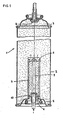
- the pressure cell 1 consists of a frame 2, which is closed at the top with a dome 3.
- the dome 3 has a flanged edge, which connects the dome and frame together and at the same time brings about a tight connection of the parts.
- the dome 3 is made of a round plate, a molded part cut out of sheet metal, which has been obtained by forming the curved shape shown in the drawing.
- the inner edge of the mandrel 3 is in turn flanged and receives a valve plate with a valve 4.
- the bottom 5 is also connected via a flanged edge with the frame 2 and has in its center on a base plate 6, above which the inner sleeve 7 is located.
- the inner sleeve 7 has a removable cover 8.
- Inside the inner sleeve 7 is a plunger 9, whose end is led out through a sealing element 10 below from the pressure cell.
- the plunger 9 on limiting elements, both of which act against the sealing element 10 and limit the free path length of the plunger 9 within the inner container 7.
- the plunger 9 is pressed by striking the can bottom on a solid surface and placed in an upward movement.
- the rubber-elastic sealing element 10 catches this upward movement and leads after breaking off the lid 8, the plunger 9 back to its original position.
- the can according to FIG. 1 can according to the invention with the inner sleeves according to FIG. 2 . 3 or 6 be equipped.
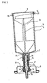
- FIG. 2 shows an inventively manufactured and used for use inner sleeve 7 with plunger 9 and cover 8.
- the inner sleeve 7 has a cylindrical wall and is closed on the plate side by a membrane.
- the plate side is followed by a cylindrical receptacle 18, which serves for fixing on the spring basket 11.
- the inner sleeve may be made of a suitable plastic, but is suitably made of aluminum.
- suitable wall thicknesses for the wall about 0.3 to 0.8 mm, for the two membranes about 0.05 to 0.10 mm.
- the inner sleeve 7 is closed with a first membrane 8, which may be made of aluminum or plastic.
- the membrane 8 has circumferentially on an edge 25 which engages over the outer edge of the inner sleeve 7.
- Between edge 25 and outer wall of the inner sleeve is a gapless layer of a against the can contents (both outer box as inner sleeve) resistant adhesive 24th
- the guided in the inner sleeve 7 plunger 9 has four wings 17, which are cut out laterally to reduce the space required.
- On the plate side there is a plate-shaped closure, which is located directly on the can side of the second membrane 15.
- the plunger 9 is chamfered in such a way that it has its membrane-closest point 16 in the periphery; upon actuation of the plunger 9, the membrane is pierced there first.
- the beveled cylindrical design of the plunger end 16 as a hollow cylinder with sharp edges then leads to a punching / cutting a cylindrical opening from the membrane eighth
- the spring basket 11 itself consists of a plastic sleeve, which is provided at its can end with an inner circumferential projection 21 which serves as an abutment for a coil spring 13 mounted therein.
- the coil spring 13 is supported on the plate side to a circumferential projection 22 of the trigger 12. In the rest position, the spring 13 exerts a pressure on the trigger 12 so that it is pressed with its sealing seat 23 against the arranged in the plate 6 ring seal 20.
- the trigger 12 terminates at its protruding from the plate 6 end in a bolt 14 which protrudes by the length of the can, the trigger 12 must be pushed in toproofsprengen over the plunger 9, the lid 8.
- the spring sleeve 11 has plate-side an extension 27 which engages behind the inner molding 19 of the base plate 6 and ensures an immovable seat on the base plate 6.
- the bottom plate 19 which has the shape of a valve plate of a conventional aerosol can, is crimped around the seal 20 and the spring basket 11 placed thereon. The crimping process ensures a solid composite of plate 6, spring cage 11 and sealing rubber 20, due to the interaction of the indentation 28 of the plate 6 and the extension 27 of the spring cage eleventh
- the trigger 12 is divided into the located within the spring basket section and a protruding pin 14, via which the triggering process is controlled.
- a tip 29 is located immediately adjacent to the second membrane 15 and acts on actuation against the bottom end of the plunger 9. The second membrane 15 is thereby destroyed, which promotes the escape of the contents of the inner sleeve into the can and the mixing of the two components.
- a likewise circumferential sealing seat 23 (FIG. Fig. 5 ), which protrudes from the pin 14 and acts with its protruding edge against the seal 20.
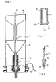
- FIG. 3 shows a second variant of an inner sleeve of a pressure cell according to the invention, in which the inner sleeve 7 and membrane 8 are integrally connected to each other. Also in this case cans as well as plate side, the inner sleeve 7 is completely sealed off from the other contents of the can. Tappet 9 and 11 spring cage have the rest in FIG. 2 shown construction and the same mode of action.
- inner sleeve 7 is preferably made in one piece, ie inner sleeve 7 and membrane 8 are not subsequently connected together.
- the wall thickness of sleeve 7 and membrane 8 are also in the range of 0.3 to 0.8 mm. Gluing or soldering of inner sleeve and membrane is also possible.
- the inner sleeve 7 is crimped both with the bottom part 5 and with the plate 6 with the introduction of the usual seals.
- the spring basket is introduced into the base plate 6 in the manner described above.
- the plunger 9 is four-winged to ensure proper guidance within the inner sleeve 7, wherein the wings are cut out in the central region. On the membrane side, the four wings are completely formed and evenly chamfered so that a membrane-next point 16 is formed, which initiates the tearing process on the membrane 8 upon actuation of the trigger and plunger.
- the tearing process is characterized by the pressure prevailing in the can, which is significantly increased in relation to that in the inner sleeve and a denting of the membrane 8 in the inner sleeve, so that they are in the region of the membrane-closest point 16 of the plunger 9 to the plunger cross invested, promoted.
- FIG. 4 shows an inventively usable spring cage 11 with a can-side abutment 21 for the coil spring mounted therein and a plate provided extension 27 for crimping and fixing to the base plate 6.
- the extension 27 in the form of a circumferential bead is accompanied in this embodiment with a Anschneidung 30 at the inner edge and molding a peripheral edge 31 which is pressed against the rubber seal 20 during the crimping process with the plate 6.
- FIG. 5 shows a present invention used trigger 12 with a tip 29, the abutment 22 for the coil spring, the pin 14 and the opposite of the spring-mounted part of the trigger and the pin 14 projecting, but against the abutment 22 recessed sealing seat 23, which is provided with a force acting against the seal 20 circumferential edge; in the sectional view, this represents a slight undercut.
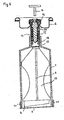
- FIG. 6 shows a further preferred embodiment of an invention to be used inner sleeve 7 with arrangement on a valve disc. 6
- the arrangement of the inner sleeve on the valve plate 6 has the advantage that the aerosol can need not have a specially designed bottom portion.
- the inner sleeve 7 with plunger 9 and cover 8 has the plate side, the second diaphragm 15, which hermetically seals the inner sleeve thereto to the plate.
- the plate side is followed by a cylindrical receptacle 18, which serves for fixing on the spring cage 11.
- the inner sleeve 7 On the bottom side, the inner sleeve 7 has a membrane 8 screwed onto it, the outer wall of which is provided with an internal thread which cooperates with an external thread on the inner sleeve 7. For hermetic sealing of the threaded area is consistently provided with an adhesive layer.
- the construction of the inner sleeve corresponds to FIG. 6 those in FIG. 2 .
- the inner sleeve 7 is plugged with its receptacle 18 on the can-side end of the spring cage 11 with this fixed, that a detachment upon actuation of the trigger 12 is excluded.
- the connection is advantageously carried out in that the receptacle 18 is verclincht to the spring cage 11, preferably such that the free end of the receptacle 18 about an outer circumferential projection 32 (see FIG. 7 ) of the spring basket 11 is guided around.
- the spring cage 11 with the trigger 12 at the same time part of the valve mechanism it is expedient to physically separate the trigger 12 from the trigger pin 14.
- the trigger 12 has a receptacle 33 for the release pin 14, which receives the release pin for the release operation, from which the release pin can be pulled out again after triggering.
- the same shot then takes a conventional spray head, as it is used for aerosol cans.
- Preferred are so-called female valves with lateral slots and a pin which projects into the receptacle 33.
- the valve In order to facilitate the access of the can contents in the spring sleeve and thus the valve, it is expedient to provide at least one opening 34 in the spring cage itself. After release of the inner sleeve and replacement of the trigger pin 14 against a spray head, the pressure can contents through the opening (s) 34 flow into the spring cage and be discharged through the actuated valve 4 from the pressure cell.
- the openings 34 have in the embodiment according to FIG. 6 another function in connection with the filling of the can.
- the filled inner sleeve is applied with the valve plate on the can end and crimped with this.
- the can is filled with the propellant gas through the valve opening, typically propane, butane, dimethyl ether and / or fluorohydrocarbon (134a).
- the filling of the can takes place with a pressure of up to 60 bar in order to make the process as short as possible in terms of time. At a pressure of up to 60 bar but there is a risk that the membrane 15 bursts under this pressure itself or by the action of the pressure-actuated trigger 12.
- the openings 34 in the valve basket 11 are provided at the plate-side end of the valve basket, as close as possible to the valve itself.
- the valve-side sealing is effected by a provided at its plate end sealing seat 23 in the form of a circumferential projection which against the seal 20 between the spring cage 11 and Plate 6 in the region of the central formation 19 acts.
- the distance of the trigger 12 to the membrane 15 must be reflected in the length of the trigger pin 14, such that the trigger pin has an overall length, the distance of the trigger 12 to the diaphragm and further to the path of the plunger 9, the this must cover for tearing the membrane 8 corresponds.
- the spring travel is correspondingly long.
- FIG. 7 shows a representation of the spring cage with trigger 12 according to FIG. 6 in detail.
- the valve disk 6 has in its central region a molding 19 with an opening, in the can side, a seal 20 in the form of a perforated disc, preferably made of a rubber-like material is used.
- the spring cage 11 is fixed via its extension 27.
- the head edge arranged peripheral edge 31 acts against the rubber seal 20 and seals the can contents against the central opening in the plate and in the seal 20 from. Due to the Verkrimpungsprozeß in the formation of the spring cage 11 in the central indentation 19 of the valve disc 6, the individual components are positively and non-positively and sealingly connected.
- the free end of the receptacle 18 is guided around an outer circumferential projection 32 of the spring basket 11.
- the spring cage 11 has immediately below the fixing on the valve plate 6 openings 34, which allow the can contents to penetrate into the spring basket.
- the coil spring 13 Inside the spring basket 11 is the coil spring 13, which is supported on an inner projection 21 of the spring cage 11 and against an outer projection 22 of the trigger 12. In a relaxed state, the coil spring 13 presses the trigger 12 with its peripheral edge 23 against the sealing rubber 20, so that the pressure cell is closed in this state.
- a conventional valve is inserted into the recess 33, which is actuated by pressing.
- the trigger moves by a defined path into the can so that the can contents can pass unhindered through the apertures 34 into and out of the spring cage.
- the openings 34 also have the purpose of allowing the already sealed can with propellant gas to pass through the central opening in the gasket 20 to allow the propellant gas to travel quickly into the can contents.
- the propellant gas supply through the gasket 20 through the propellant gas is pressed with the intended pressure in the spring sleeve, so that the trigger 12 moves by a defined path in the direction of the membrane 15, but without reaching them, so that after the release of the Openings 34, the gas can escape under relaxation laterally into the can.
- Pressure cans according to the embodiment according to FIG. 6 are used "head down" during use, ie the valve points downwards. Pressure cans according to Figures 2 and 3 can be used upright when installing a riser or, in the absence of a riser, upside down. The use with spray guns is possible and intended.
- can side in the application refers to a can-inward arrangement
- ish-side designates an arrangement to the respective plate (in the valve or bottom region).
Landscapes
- Chemical & Material Sciences (AREA)
- Dispersion Chemistry (AREA)
- Engineering & Computer Science (AREA)
- Mechanical Engineering (AREA)
- Containers And Packaging Bodies Having A Special Means To Remove Contents (AREA)
- Processing And Handling Of Plastics And Other Materials For Molding In General (AREA)
- Nozzles (AREA)
- Mixers Of The Rotary Stirring Type (AREA)
Claims (21)
- Capsule sous pression avec un corps (2), un dôme (3) destiné à recevoir une vanne (4), un fond bombé (5), une douille intérieure (7) placée sur un plateau (6), un poinçon (9) placé dans la douille intérieure (7) pour faire éclater la douille intérieure (7), qui peut être actionné à travers le plateau (6), la douille intérieure (7) étant reliée au plateau (6) par l'intermédiaire d'une cage ressort (11), la cage ressort (11) contenant un déclencheur (12) soutenu élastiquement, qui agit sur le poinçon (9), lequel poinçon (9) agit contre une fermeture (8) placée à l'extrémité côté capsule de la douille intérieure (7), caractérisée en ce que la fermeture (8) est une membrane qui ferme hermétiquement la douille intérieure (7) au niveau de son extrémité côté capsule par rapport au contenu de la capsule sous pression (1) et est déchirée par le poinçon (9) lors d'une action sur le déclencheur (12) ; la pression dans la douille intérieure (7) étant plus faible que la pression à l'extérieur de la douille intérieure (7) et la membrane (8) étant bombée en direction de l'intérieur de la douille intérieure (7) et dans laquelle :- la douille intérieure (7) et la membrane (8) sont fabriquées d'un seul tenant ou- la membrane (8) est collée à la douille intérieure (7) et vissée en plus à la douille intérieure (7).
- Capsule sous pression selon la revendication 1, caractérisée en ce que la douille intérieure (7) présente, à son extrémité extérieure, un logement (18) pour la fixation sur la cage ressort (11).
- Capsule sous pression selon la revendication 1 ou 2, caractérisée en ce qu'une seconde membrane (15) est placée au niveau de la transition entre la douille intérieure (7) et le logement (18).
- Capsule sous pression selon la revendication 2 ou 3, caractérisée en ce que le logement (18) est serti à une cage ressort (11).
- Capsule sous pression selon la revendication 4, caractérisée en ce que l'extrémité libre du logement (18) passe autour d'une saillie périphérique extérieure (32) de la cage ressort (11).
- Capsule sous pression selon l'une des revendications précédentes, caractérisée en ce que la douille intérieure (7) est placée sur un plateau (6), dans le fond (5) de la capsule sous pression (1).
- Capsule sous pression selon l'une des revendications 1 à 5, caractérisée en ce que le plateau (6) est placé avec la douille intérieure (7) dans le dôme (2) de la capsule sous pression (1).
- Capsule sous pression selon la revendication 7, caractérisée en ce que le déclencheur (12) présente un logement (33) pour un ergot de déclenchement (14) ou une tête de pulvérisation.
- Capsule sous pression selon l'une des revendications 1 à 8, caractérisée en ce que la cage ressort (11) est fixée dans un évidement central (19) du plateau (6).
- Capsule sous pression selon l'une des revendications précédentes, caractérisée en ce que le poinçon (9) présente plusieurs ailettes (17) le long d'un axe central.
- Capsule sous pression selon la revendication 10, caractérisée en ce que le poinçon (9) présente à son extrémité côté capsule la forme d'un cylindre creux (16) biseauté et à arêtes vives.
- Capsule sous pression selon la revendication 10 ou 11, caractérisée en ce que les ailettes (17) présentent des découpes et/ou des évidements.
- Capsule sous pression selon l'une des revendications précédentes, caractérisée par un joint (20) entre la cage ressort (11) et le plateau (6) dans la zone de l'évidement central (19).
- Capsule sous pression selon l'une des revendications précédentes, caractérisée en ce que la cage ressort (11) présente une saillie intérieure (21) en tant que contre-appui pour un élément ressort (13) au niveau de son extrémité côté vanne.
- Capsule sous pression selon la revendication 9, caractérisée en ce que le déclencheur (12) présente à son extrémité côté plateau une saillie périphérique-(22) en tant que contre-appui pour l'élément ressort (13).
- Capsule sous pression selon l'une des revendications précédentes, caractérisée en ce que le déclencheur (12) présente à son extrémité côté plateau un siège d'étanchéité (23) en forme de saillie périphérique.
- Capsule sous pression selon l'une des revendications précédentes, caractérisée en ce que la douille intérieure (7) et la membrane (8) sont fabriquées en aluminium.
- Capsule sous pression selon l'une des revendications précédentes, caractérisée en ce que la cage ressort (11) présente au moins une traversée (34).
- Capsule sous pression selon la revendication 1, caractérisée en ce que la membrane (8) est collée à la douille intérieure au moyen d'un adhésif à deux composants.
- Capsule sous pression selon la revendication 19, caractérisée en ce que l'adhésif est un système époxy/amine réticulant ou un système polyisocyanate/durcisseur.
- Utilisation de la capsule sous pression selon l'une des revendications 1 à 20 pour des systèmes liquides à deux composants, en particulier des mousses d'étanchéité à deux composants, des adhésifs à deux composants ou des vernis à deux composants.
Applications Claiming Priority (3)
| Application Number | Priority Date | Filing Date | Title |
|---|---|---|---|
| DE10260117A DE10260117A1 (de) | 2002-12-19 | 2002-12-19 | Druckdose zum Mischen und Ausbringen zweikomponentiger Werkstoffe |
| DE10260117 | 2002-12-19 | ||
| PCT/EP2003/014662 WO2004056660A2 (fr) | 2002-12-19 | 2003-12-19 | Capsule sous pression pour melanger et produire des materiaux a deux composantes |
Publications (3)
| Publication Number | Publication Date |
|---|---|
| EP1578676A2 EP1578676A2 (fr) | 2005-09-28 |
| EP1578676B1 EP1578676B1 (fr) | 2007-05-02 |
| EP1578676B2 true EP1578676B2 (fr) | 2009-10-21 |
Family
ID=32404089
Family Applications (1)
| Application Number | Title | Priority Date | Filing Date |
|---|---|---|---|
| EP03813585A Expired - Lifetime EP1578676B2 (fr) | 2002-12-19 | 2003-12-19 | Capsule sous pression pour melanger et produire des materiaux a deux composantes |
Country Status (10)
| Country | Link |
|---|---|
| US (1) | US8403177B2 (fr) |
| EP (1) | EP1578676B2 (fr) |
| JP (1) | JP4412605B2 (fr) |
| AT (1) | ATE361247T1 (fr) |
| AU (1) | AU2003300539A1 (fr) |
| CA (1) | CA2508873C (fr) |
| DE (2) | DE10260117A1 (fr) |
| DK (1) | DK1578676T4 (fr) |
| ES (1) | ES2286510T5 (fr) |
| WO (1) | WO2004056660A2 (fr) |
Families Citing this family (17)
| Publication number | Priority date | Publication date | Assignee | Title |
|---|---|---|---|---|
| DE10144133A1 (de) * | 2001-09-07 | 2003-03-27 | Peter Kwasny Gmbh | Zweikomponenten-Epoxid-Lacksprühdose |
| DE102006056280A1 (de) | 2006-04-25 | 2007-10-31 | Fazekas, Gàbor | Druckdose mit Innenhülse |
| DE102007006097A1 (de) * | 2007-02-02 | 2008-08-07 | Kwasny Gmbh | Zweikomponentendruckdose mit abgedichtetem Auslösemechanismus |
| CN104609044A (zh) * | 2015-01-26 | 2015-05-13 | 中山市美捷时包装制品有限公司 | 一种刺穿型阀门 |
| CN104609045A (zh) * | 2015-01-26 | 2015-05-13 | 中山市美捷时包装制品有限公司 | 一种混合气雾剂喷漆装置 |
| CN104959279B (zh) * | 2015-07-02 | 2017-06-06 | 华东光电集成器件研究所 | 一种搅拌式气压点胶阀 |
| AU2017264964B2 (en) | 2016-05-13 | 2021-11-25 | MSI Coatings Inc. | System and method for using a VOC free low radiant flux LED UV curable composition |
| GB2558522A (en) * | 2016-06-20 | 2018-07-18 | Kind Consumer Ltd | A pressurised Container |
| WO2019027985A1 (fr) | 2017-07-31 | 2019-02-07 | V1 Enterprises, LLC | Appareil de mélange, procédé de fabrication et d'utilisation |
| CN107310857A (zh) * | 2017-08-05 | 2017-11-03 | 中山市美捷时包装制品有限公司 | 一种二元包装气雾剂阀罐装置 |
| AU2018373927B2 (en) | 2017-11-27 | 2024-01-18 | Sika Technology Ag | Two-component pressurized can |
| US11338320B1 (en) * | 2018-02-03 | 2022-05-24 | MSI Coatings Inc. | Composition for aerosol cans, method of making and using the same |
| MY193870A (en) * | 2018-05-31 | 2022-10-29 | Boon Leong Saw | A container for aerosol system |
| CN110104306A (zh) * | 2019-04-29 | 2019-08-09 | 深圳市佳鑫一帆科技有限公司 | 一种填缝胶水用具有防泄漏功能的存储装置 |
| MY202306A (en) * | 2019-05-31 | 2024-04-23 | Orientus Ind Sdn Bhd | Spray can valve and cushioning pad |
| USD913067S1 (en) | 2019-07-01 | 2021-03-16 | V1 Enterprises, LLC | Mixing apparatus |
| DE102021108237A1 (de) | 2021-03-31 | 2022-10-06 | Peter Kwasny Gmbh | 2-Komponentiges Lacksystem |
Citations (2)
| Publication number | Priority date | Publication date | Assignee | Title |
|---|---|---|---|---|
| WO1998038104A1 (fr) † | 1997-02-28 | 1998-09-03 | Bormioli Rocco & Figlio S.P.A. | Emballage permettant de maintenir separes les produits avant utilisation |
| US6305576B1 (en) † | 2000-01-19 | 2001-10-23 | Nalge Nunc International Corporation | Cartridge for aseptically holding and dispensing a fluid material, and a container and method for aseptically holding and mixing the fluid material |
Family Cites Families (14)
| Publication number | Priority date | Publication date | Assignee | Title |
|---|---|---|---|---|
| US2786769A (en) * | 1955-03-08 | 1957-03-26 | Greenspan Irving | Nursing bottle |
| US3240391A (en) * | 1962-07-17 | 1966-03-15 | Merlin E Garton | Spray container |
| US3425589A (en) * | 1967-05-31 | 1969-02-04 | Nat Can Corp | Composite container unit |
| DE3237263A1 (de) * | 1982-10-08 | 1984-04-12 | Deutsche Präzisions-Ventil GmbH, 6234 Hattersheim | Ventilsystem fuer druckgaspackung mit zweikomponentenprodukt |
| DE3610345C2 (de) * | 1986-03-27 | 1998-07-09 | Rathor Ag | Vorrichtung zur Erzeugung von Polyurethan-Montageschaum |
| CA1249886A (fr) * | 1986-05-02 | 1989-02-07 | Claude J. Champagne | Methode de transmission de donnees duplex utilisant un protocole d'emission avec attente |
| JPH0626686B2 (ja) * | 1987-03-24 | 1994-04-13 | 大阪エヤゾ−ル工業株式会社 | 内容物混合容器および該容器を用いた内容物混合吐出装置 |
| DE8707230U1 (fr) * | 1987-05-20 | 1988-09-15 | Wella Ag, 6100 Darmstadt, De | |
| IL119370A0 (en) | 1996-10-07 | 1997-01-10 | Sharon Igal | Container for dispensing formulations |
| JP4290297B2 (ja) * | 1999-12-17 | 2009-07-01 | エア・ウォーター・ゾル株式会社 | 混合型エアゾール用容器 |
| US6533113B2 (en) * | 2000-12-01 | 2003-03-18 | Brett Moscovitz | System, devices and methods for storing and mixing substances |
| DE10114624B4 (de) * | 2001-03-23 | 2006-05-04 | Peter Kwasny Gmbh | Druckdose und ihre Verwendung für 2-Komponentensysteme |
| DE102004024777A1 (de) * | 2004-05-17 | 2005-12-15 | Fazekas, Gàbor | Druckdose mit Innenhülse |
| US7270233B2 (en) * | 2005-07-21 | 2007-09-18 | Kindt John H | Package for separate compounds to be mixed |
-
2002
- 2002-12-19 DE DE10260117A patent/DE10260117A1/de not_active Withdrawn
-
2003
- 2003-12-19 ES ES03813585T patent/ES2286510T5/es not_active Expired - Lifetime
- 2003-12-19 DK DK03813585.1T patent/DK1578676T4/da active
- 2003-12-19 AT AT03813585T patent/ATE361247T1/de active
- 2003-12-19 US US10/539,459 patent/US8403177B2/en active Active
- 2003-12-19 DE DE50307203T patent/DE50307203D1/de not_active Expired - Lifetime
- 2003-12-19 EP EP03813585A patent/EP1578676B2/fr not_active Expired - Lifetime
- 2003-12-19 AU AU2003300539A patent/AU2003300539A1/en not_active Abandoned
- 2003-12-19 WO PCT/EP2003/014662 patent/WO2004056660A2/fr active IP Right Grant
- 2003-12-19 CA CA2508873A patent/CA2508873C/fr not_active Expired - Lifetime
- 2003-12-19 JP JP2004561396A patent/JP4412605B2/ja not_active Expired - Lifetime
Patent Citations (2)
| Publication number | Priority date | Publication date | Assignee | Title |
|---|---|---|---|---|
| WO1998038104A1 (fr) † | 1997-02-28 | 1998-09-03 | Bormioli Rocco & Figlio S.P.A. | Emballage permettant de maintenir separes les produits avant utilisation |
| US6305576B1 (en) † | 2000-01-19 | 2001-10-23 | Nalge Nunc International Corporation | Cartridge for aseptically holding and dispensing a fluid material, and a container and method for aseptically holding and mixing the fluid material |
Also Published As
| Publication number | Publication date |
|---|---|
| CA2508873A1 (fr) | 2004-07-08 |
| US8403177B2 (en) | 2013-03-26 |
| EP1578676B1 (fr) | 2007-05-02 |
| JP4412605B2 (ja) | 2010-02-10 |
| DK1578676T4 (da) | 2010-03-01 |
| DK1578676T3 (da) | 2007-09-10 |
| JP2006510552A (ja) | 2006-03-30 |
| WO2004056660A3 (fr) | 2004-09-10 |
| ATE361247T1 (de) | 2007-05-15 |
| AU2003300539A1 (en) | 2004-07-14 |
| DE10260117A1 (de) | 2004-07-01 |
| EP1578676A2 (fr) | 2005-09-28 |
| CA2508873C (fr) | 2011-03-29 |
| ES2286510T3 (es) | 2007-12-01 |
| US20060201969A1 (en) | 2006-09-14 |
| ES2286510T5 (es) | 2010-02-15 |
| AU2003300539A8 (en) | 2004-07-14 |
| WO2004056660A2 (fr) | 2004-07-08 |
| DE50307203D1 (de) | 2007-06-14 |
Similar Documents
| Publication | Publication Date | Title |
|---|---|---|
| EP1373094B1 (fr) | Recipient sous pression permettant de melanger et de distribuer des materiaux a deux composants | |
| EP1578676B2 (fr) | Capsule sous pression pour melanger et produire des materiaux a deux composantes | |
| WO2017121798A1 (fr) | Cartouche pour substrat de boisson ou d'aliment | |
| EP1344500A1 (fr) | Capsule de mélange de plusieurs composants, en particulier pour l'art dentaire | |
| EP0152761B1 (fr) | Dispositif pour la fabrication et la vaporisation d'un mélange constitué d'au moins deux composants, p.e. liquides, et d'un gaz sous pression | |
| EP2013115B1 (fr) | Récipient sous pression à manchon interne | |
| EP0625468B1 (fr) | Récipient aérosol à deux composants | |
| DE3405064A1 (de) | Vorrichtung zum herstellen und verspruehen einer aus wenigstens zwei komponenten, z. b. fluessigkeiten, und einem treibgas bestehenden mischung | |
| EP2106372A1 (fr) | Bouchon de fermeture comprenant un compartiment de libération fermé destiné à un additif pour boisson | |
| EP2114795B1 (fr) | Réceptacle sous pression pour deux composants à mécanisme de déclenchement étanche | |
| WO2011073251A1 (fr) | Cartouche avec bouchon de fermeture | |
| EP3717378B1 (fr) | Récipient sous pression à deux composants | |
| EP3652083B1 (fr) | Fermeture de récipient dotée d'une capsule standard | |
| EP3741710B1 (fr) | Récipient sous pression pourvu de manchon intérieur | |
| WO2020224897A1 (fr) | Cartouche comprenant un élément de tête | |
| DE2839284A1 (de) | Einhandverschluss fuer tuben u.dgl. | |
| EP0200164A1 (fr) | Dispositif pour mélanger et distribuer un mélange composé par au moins deux composantes, par exemple des liquides et un gaz propulseur | |
| DE3208969A1 (de) | Behaeltnis fuer zwei-komponenten-materialien | |
| WO2005100204A1 (fr) | Recipient sous pression servant a distribuer des formulations a plusieurs composants | |
| EP3380411A1 (fr) | Contenant de conservation d'un ingrédient |
Legal Events
| Date | Code | Title | Description |
|---|---|---|---|
| PUAI | Public reference made under article 153(3) epc to a published international application that has entered the european phase |
Free format text: ORIGINAL CODE: 0009012 |
|
| 17P | Request for examination filed |
Effective date: 20050716 |
|
| AK | Designated contracting states |
Kind code of ref document: A2 Designated state(s): AT BE BG CH CY CZ DE DK EE ES FI FR GB GR HU IE IT LI LU MC NL PT RO SE SI SK TR |
|
| AX | Request for extension of the european patent |
Extension state: AL LT LV MK |
|
| DAX | Request for extension of the european patent (deleted) | ||
| GRAP | Despatch of communication of intention to grant a patent |
Free format text: ORIGINAL CODE: EPIDOSNIGR1 |
|
| GRAS | Grant fee paid |
Free format text: ORIGINAL CODE: EPIDOSNIGR3 |
|
| GRAA | (expected) grant |
Free format text: ORIGINAL CODE: 0009210 |
|
| AK | Designated contracting states |
Kind code of ref document: B1 Designated state(s): AT BE BG CH CY CZ DE DK EE ES FI FR GB GR HU IE IT LI LU MC NL PT RO SE SI SK TR |
|
| PG25 | Lapsed in a contracting state [announced via postgrant information from national office to epo] |
Ref country code: FI Free format text: LAPSE BECAUSE OF FAILURE TO SUBMIT A TRANSLATION OF THE DESCRIPTION OR TO PAY THE FEE WITHIN THE PRESCRIBED TIME-LIMIT Effective date: 20070502 |
|
| REG | Reference to a national code |
Ref country code: GB Ref legal event code: FG4D Free format text: NOT ENGLISH |
|
| REG | Reference to a national code |
Ref country code: CH Ref legal event code: EP |
|
| REG | Reference to a national code |
Ref country code: IE Ref legal event code: FG4D Free format text: LANGUAGE OF EP DOCUMENT: GERMAN |
|
| REF | Corresponds to: |
Ref document number: 50307203 Country of ref document: DE Date of ref document: 20070614 Kind code of ref document: P |
|
| REG | Reference to a national code |
Ref country code: CH Ref legal event code: NV Representative=s name: BUECHEL, KAMINSKI & PARTNER PATENTANWAELTE ESTABLI |
|
| REG | Reference to a national code |
Ref country code: SE Ref legal event code: TRGR |
|
| GBT | Gb: translation of ep patent filed (gb section 77(6)(a)/1977) |
Effective date: 20070809 |
|
| REG | Reference to a national code |
Ref country code: DK Ref legal event code: T3 |
|
| ET | Fr: translation filed | ||
| REG | Reference to a national code |
Ref country code: ES Ref legal event code: FG2A Ref document number: 2286510 Country of ref document: ES Kind code of ref document: T3 |
|
| REG | Reference to a national code |
Ref country code: IE Ref legal event code: FD4D |
|
| PG25 | Lapsed in a contracting state [announced via postgrant information from national office to epo] |
Ref country code: IE Free format text: LAPSE BECAUSE OF FAILURE TO SUBMIT A TRANSLATION OF THE DESCRIPTION OR TO PAY THE FEE WITHIN THE PRESCRIBED TIME-LIMIT Effective date: 20070502 Ref country code: SI Free format text: LAPSE BECAUSE OF FAILURE TO SUBMIT A TRANSLATION OF THE DESCRIPTION OR TO PAY THE FEE WITHIN THE PRESCRIBED TIME-LIMIT Effective date: 20070502 Ref country code: BG Free format text: LAPSE BECAUSE OF FAILURE TO SUBMIT A TRANSLATION OF THE DESCRIPTION OR TO PAY THE FEE WITHIN THE PRESCRIBED TIME-LIMIT Effective date: 20070802 Ref country code: PT Free format text: LAPSE BECAUSE OF FAILURE TO SUBMIT A TRANSLATION OF THE DESCRIPTION OR TO PAY THE FEE WITHIN THE PRESCRIBED TIME-LIMIT Effective date: 20071002 |
|
| PLBI | Opposition filed |
Free format text: ORIGINAL CODE: 0009260 |
|
| PG25 | Lapsed in a contracting state [announced via postgrant information from national office to epo] |
Ref country code: SK Free format text: LAPSE BECAUSE OF FAILURE TO SUBMIT A TRANSLATION OF THE DESCRIPTION OR TO PAY THE FEE WITHIN THE PRESCRIBED TIME-LIMIT Effective date: 20070502 |
|
| PLAX | Notice of opposition and request to file observation + time limit sent |
Free format text: ORIGINAL CODE: EPIDOSNOBS2 |
|
| 26 | Opposition filed |
Opponent name: MOTIP DUPLI GMBH Effective date: 20080204 |
|
| PG25 | Lapsed in a contracting state [announced via postgrant information from national office to epo] |
Ref country code: GR Free format text: LAPSE BECAUSE OF FAILURE TO SUBMIT A TRANSLATION OF THE DESCRIPTION OR TO PAY THE FEE WITHIN THE PRESCRIBED TIME-LIMIT Effective date: 20070803 |
|
| NLR1 | Nl: opposition has been filed with the epo |
Opponent name: MOTIP DUPLI GMBH |
|
| PG25 | Lapsed in a contracting state [announced via postgrant information from national office to epo] |
Ref country code: RO Free format text: LAPSE BECAUSE OF FAILURE TO SUBMIT A TRANSLATION OF THE DESCRIPTION OR TO PAY THE FEE WITHIN THE PRESCRIBED TIME-LIMIT Effective date: 20070502 |
|
| PLBB | Reply of patent proprietor to notice(s) of opposition received |
Free format text: ORIGINAL CODE: EPIDOSNOBS3 |
|
| PG25 | Lapsed in a contracting state [announced via postgrant information from national office to epo] |
Ref country code: MC Free format text: LAPSE BECAUSE OF NON-PAYMENT OF DUE FEES Effective date: 20071231 |
|
| PG25 | Lapsed in a contracting state [announced via postgrant information from national office to epo] |
Ref country code: EE Free format text: LAPSE BECAUSE OF FAILURE TO SUBMIT A TRANSLATION OF THE DESCRIPTION OR TO PAY THE FEE WITHIN THE PRESCRIBED TIME-LIMIT Effective date: 20070502 |
|
| PG25 | Lapsed in a contracting state [announced via postgrant information from national office to epo] |
Ref country code: CY Free format text: LAPSE BECAUSE OF FAILURE TO SUBMIT A TRANSLATION OF THE DESCRIPTION OR TO PAY THE FEE WITHIN THE PRESCRIBED TIME-LIMIT Effective date: 20070502 |
|
| PG25 | Lapsed in a contracting state [announced via postgrant information from national office to epo] |
Ref country code: LU Free format text: LAPSE BECAUSE OF NON-PAYMENT OF DUE FEES Effective date: 20071219 |
|
| PUAH | Patent maintained in amended form |
Free format text: ORIGINAL CODE: 0009272 |
|
| STAA | Information on the status of an ep patent application or granted ep patent |
Free format text: STATUS: PATENT MAINTAINED AS AMENDED |
|
| PG25 | Lapsed in a contracting state [announced via postgrant information from national office to epo] |
Ref country code: HU Free format text: LAPSE BECAUSE OF FAILURE TO SUBMIT A TRANSLATION OF THE DESCRIPTION OR TO PAY THE FEE WITHIN THE PRESCRIBED TIME-LIMIT Effective date: 20071103 Ref country code: TR Free format text: LAPSE BECAUSE OF FAILURE TO SUBMIT A TRANSLATION OF THE DESCRIPTION OR TO PAY THE FEE WITHIN THE PRESCRIBED TIME-LIMIT Effective date: 20070502 |
|
| REG | Reference to a national code |
Ref country code: CH Ref legal event code: PFA Owner name: PETER KWASNY GMBH Free format text: PETER KWASNY GMBH#HEILBRONNER STRASSE 96#74831 GUNDELSHEIM (DE) -TRANSFER TO- PETER KWASNY GMBH#HEILBRONNER STRASSE 96#74831 GUNDELSHEIM (DE) |
|
| 27A | Patent maintained in amended form |
Effective date: 20091021 |
|
| AK | Designated contracting states |
Kind code of ref document: B2 Designated state(s): AT BE BG CH CY CZ DE DK EE ES FI FR GB GR HU IE IT LI LU MC NL PT RO SE SI SK TR |
|
| REG | Reference to a national code |
Ref country code: CH Ref legal event code: AEN Free format text: AUFRECHTERHALTUNG DES PATENTES IN GEAENDERTER FORM |
|
| NLR2 | Nl: decision of opposition |
Effective date: 20091021 |
|
| NLR3 | Nl: receipt of modified translations in the netherlands language after an opposition procedure | ||
| REG | Reference to a national code |
Ref country code: SE Ref legal event code: RPEO |
|
| REG | Reference to a national code |
Ref country code: ES Ref legal event code: DC2A Date of ref document: 20091130 Kind code of ref document: T5 |
|
| REG | Reference to a national code |
Ref country code: DK Ref legal event code: T4 |
|
| PG25 | Lapsed in a contracting state [announced via postgrant information from national office to epo] |
Ref country code: IT Free format text: LAPSE BECAUSE OF NON-PAYMENT OF DUE FEES Effective date: 20101219 |
|
| REG | Reference to a national code |
Ref country code: FR Ref legal event code: PLFP Year of fee payment: 13 |
|
| REG | Reference to a national code |
Ref country code: FR Ref legal event code: PLFP Year of fee payment: 14 |
|
| REG | Reference to a national code |
Ref country code: FR Ref legal event code: PLFP Year of fee payment: 15 |
|
| PGFP | Annual fee paid to national office [announced via postgrant information from national office to epo] |
Ref country code: SE Payment date: 20221222 Year of fee payment: 20 Ref country code: NL Payment date: 20221222 Year of fee payment: 20 Ref country code: GB Payment date: 20221222 Year of fee payment: 20 Ref country code: FR Payment date: 20221222 Year of fee payment: 20 Ref country code: DK Payment date: 20221223 Year of fee payment: 20 Ref country code: DE Payment date: 20221213 Year of fee payment: 20 Ref country code: CZ Payment date: 20221212 Year of fee payment: 20 Ref country code: AT Payment date: 20221222 Year of fee payment: 20 |
|
| PGFP | Annual fee paid to national office [announced via postgrant information from national office to epo] |
Ref country code: BE Payment date: 20221221 Year of fee payment: 20 |
|
| PGFP | Annual fee paid to national office [announced via postgrant information from national office to epo] |
Ref country code: ES Payment date: 20230224 Year of fee payment: 20 Ref country code: CH Payment date: 20230103 Year of fee payment: 20 |
|
| PGFP | Annual fee paid to national office [announced via postgrant information from national office to epo] |
Ref country code: IT Payment date: 20221228 Year of fee payment: 20 |
|
| P01 | Opt-out of the competence of the unified patent court (upc) registered |
Effective date: 20230428 |
|
| REG | Reference to a national code |
Ref country code: DE Ref legal event code: R071 Ref document number: 50307203 Country of ref document: DE |
|
| REG | Reference to a national code |
Ref country code: NL Ref legal event code: MK Effective date: 20231218 |
|
| REG | Reference to a national code |
Ref country code: CH Ref legal event code: PL Ref country code: ES Ref legal event code: FD2A Effective date: 20231229 |
|
| REG | Reference to a national code |
Ref country code: DK Ref legal event code: EUP Expiry date: 20231219 |
|
| REG | Reference to a national code |
Ref country code: GB Ref legal event code: PE20 Expiry date: 20231218 |
|
| PG25 | Lapsed in a contracting state [announced via postgrant information from national office to epo] |
Ref country code: GB Free format text: LAPSE BECAUSE OF EXPIRATION OF PROTECTION Effective date: 20231218 |
|
| REG | Reference to a national code |
Ref country code: BE Ref legal event code: MK Effective date: 20231219 |
|
| PG25 | Lapsed in a contracting state [announced via postgrant information from national office to epo] |
Ref country code: ES Free format text: LAPSE BECAUSE OF EXPIRATION OF PROTECTION Effective date: 20231220 |
|
| REG | Reference to a national code |
Ref country code: SE Ref legal event code: EUG |
|
| PG25 | Lapsed in a contracting state [announced via postgrant information from national office to epo] |
Ref country code: GB Free format text: LAPSE BECAUSE OF EXPIRATION OF PROTECTION Effective date: 20231218 Ref country code: ES Free format text: LAPSE BECAUSE OF EXPIRATION OF PROTECTION Effective date: 20231220 Ref country code: CZ Free format text: LAPSE BECAUSE OF EXPIRATION OF PROTECTION Effective date: 20231219 |
|
| REG | Reference to a national code |
Ref country code: AT Ref legal event code: MK07 Ref document number: 361247 Country of ref document: AT Kind code of ref document: T Effective date: 20231219 |