EP1578563B1 - Drill hammer - Google Patents
Drill hammer Download PDFInfo
- Publication number
- EP1578563B1 EP1578563B1 EP03814446A EP03814446A EP1578563B1 EP 1578563 B1 EP1578563 B1 EP 1578563B1 EP 03814446 A EP03814446 A EP 03814446A EP 03814446 A EP03814446 A EP 03814446A EP 1578563 B1 EP1578563 B1 EP 1578563B1
- Authority
- EP
- European Patent Office
- Prior art keywords
- hammer
- tool holder
- piston
- tube
- idling
- Prior art date
- Legal status (The legal status is an assumption and is not a legal conclusion. Google has not performed a legal analysis and makes no representation as to the accuracy of the status listed.)
- Expired - Lifetime
Links
- 238000009527 percussion Methods 0.000 claims description 9
- 238000013022 venting Methods 0.000 claims 1
- 238000004519 manufacturing process Methods 0.000 abstract description 2
- 238000006073 displacement reaction Methods 0.000 description 4
- 230000002093 peripheral effect Effects 0.000 description 3
- 238000010304 firing Methods 0.000 description 2
- 230000006835 compression Effects 0.000 description 1
- 238000007906 compression Methods 0.000 description 1
- 239000013013 elastic material Substances 0.000 description 1
- 230000004048 modification Effects 0.000 description 1
- 238000012986 modification Methods 0.000 description 1
- 230000000149 penetrating effect Effects 0.000 description 1
Images
Classifications
-
- B—PERFORMING OPERATIONS; TRANSPORTING
- B25—HAND TOOLS; PORTABLE POWER-DRIVEN TOOLS; MANIPULATORS
- B25D—PERCUSSIVE TOOLS
- B25D17/00—Details of, or accessories for, portable power-driven percussive tools
- B25D17/06—Hammer pistons; Anvils ; Guide-sleeves for pistons
-
- B—PERFORMING OPERATIONS; TRANSPORTING
- B25—HAND TOOLS; PORTABLE POWER-DRIVEN TOOLS; MANIPULATORS
- B25D—PERCUSSIVE TOOLS
- B25D11/00—Portable percussive tools with electromotor or other motor drive
- B25D11/005—Arrangements for adjusting the stroke of the impulse member or for stopping the impact action when the tool is lifted from the working surface
-
- B—PERFORMING OPERATIONS; TRANSPORTING
- B25—HAND TOOLS; PORTABLE POWER-DRIVEN TOOLS; MANIPULATORS
- B25D—PERCUSSIVE TOOLS
- B25D16/00—Portable percussive machines with superimposed rotation, the rotational movement of the output shaft of a motor being modified to generate axial impacts on the tool bit
-
- B—PERFORMING OPERATIONS; TRANSPORTING
- B25—HAND TOOLS; PORTABLE POWER-DRIVEN TOOLS; MANIPULATORS
- B25D—PERCUSSIVE TOOLS
- B25D2250/00—General details of portable percussive tools; Components used in portable percussive tools
- B25D2250/035—Bleeding holes, e.g. in piston guide-sleeves
-
- B—PERFORMING OPERATIONS; TRANSPORTING
- B25—HAND TOOLS; PORTABLE POWER-DRIVEN TOOLS; MANIPULATORS
- B25D—PERCUSSIVE TOOLS
- B25D2250/00—General details of portable percussive tools; Components used in portable percussive tools
- B25D2250/131—Idling mode of tools
-
- B—PERFORMING OPERATIONS; TRANSPORTING
- B25—HAND TOOLS; PORTABLE POWER-DRIVEN TOOLS; MANIPULATORS
- B25D—PERCUSSIVE TOOLS
- B25D2250/00—General details of portable percussive tools; Components used in portable percussive tools
- B25D2250/191—Ram catchers for stopping the ram when entering idling mode
-
- B—PERFORMING OPERATIONS; TRANSPORTING
- B25—HAND TOOLS; PORTABLE POWER-DRIVEN TOOLS; MANIPULATORS
- B25D—PERCUSSIVE TOOLS
- B25D2250/00—General details of portable percussive tools; Components used in portable percussive tools
- B25D2250/371—Use of springs
Definitions
- the invention relates to a hammer drill according to the preamble of claim 1.
- the hammer tube for guiding the cylinder or pot piston is arranged axially displaceable in the housing.
- the idle spring is supported between the hammer tube and a housing-fixed stop or spring plate.
- the idle control opening is arranged in the guide sleeve.
- the idling control opening is completed by a guide piece formed on the housing and additionally by the racket, so that an air pressure cushion can build up in the air cushion space between the piston and the racket. If the clamped in the percussion hammer or in the hammer drill tool lifted from the processing site, the idle spring presses the hammer tube forward towards the tool holder, causing the Idle control bore is pushed out of the area of the guide piece and thus is open. A negative pressure in the air cushion area between the piston and the racket, which pulls back the racket, can not build up. The racket remains in a position where its trailing edge is some distance away from the idle control bore.
- the air cushion impact mechanism is arranged in a non-rotatably on the housing and axially immovable hammer tube.
- the tool holder is held displaceably relative to the hammer tube in the housing and is supported via an idle spring on a stop fixed to the housing or hammer tube.
- an idle control port is provided for aerating the air cushion area during idling.
- a known hammer drill ( US-A 43 66 869 ) is rotatably mounted and drivable by a rotary hammer tube in the housing both rotatable and axially displaceable.
- the tool holder is rigidly connected to the hammer tube and thus participates in its rotational and translational movement.
- the means for idle control of the arranged in the hammer tube air cushion percussion again includes an idle spring and an idle control opening.
- the idle spring is disposed between the axially displaceable hammer tube and the housing.
- a well-known hammer ( EP-A 10 48 415 ) is equipped with a catch ring for the racket of a striking mechanism.
- the hammer drill according to the invention with the features of claim 1 has the advantage that the idle travel of the striking mechanism by an axial displacement of the Tool holder is ensured relative to the hammer tube, thus the hammer tube in the housing can be fixed, which allows for easier production.
- the idle travel can be made very long, so that when idle the racket can move far away from the piston. This creates a large distance between the trailing edge of the racket and the idle control opening, so that an unwanted closing of the idle control opening reliably prevented and thus a safe idle is guaranteed.
- the tool holder may be guided in the hammer tube or in the housing. In the latter case, the hammer tube can be significantly shortened.
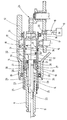
- the drawing shows a detail of a longitudinal section of a hammer drill, partially schematized, which occupies its stroke position in the upper half section and its idle position in the lower half section.
- rotary hammer has a housing 10, a protruding from the housing 10 tool holder 11 for limited axially displaceable recording of a tool, not shown here, an air cushion impact mechanism 12 and an electric motor 13.
- a hammer tube 14 is rotatably mounted, which can be offset by a bevel gear 15 of the electric motor 13 in rotation.
- the bevel gear 15 includes in the exemplary embodiment a rotatably with the hammer tube 14, preferably integrally connected, ring gear 16, meshing with the ring gear 16 bevel gear 17, and a non-rotatably connected to the bevel gear 17 gear 18 with external teeth, with a on an output shaft 19 of the Electric motor 13 trained pinion 20 meshes.
- the Bubble impact mechanism 12 comprises a hammer tube 14 axially displaceably guided pot piston 21, an axially displaceable inside the pot piston 21 guided racket 22 and a racket 22 downstream, projecting into the tool holder 11 striker or striker 23, which guided axially displaceably in the tool holder 11 is.
- the pot piston 21 is driven by a crank mechanism 24 in a reciprocating stroke movement.
- the tool holder 11 is fixed axially displaceable on the hammer tube 14 and rotatably connected thereto.
- a circumferential toothing 25 with axially directed teeth is arranged between the hammer tube 14 and the tool holder 11.
- a simple tongue and groove connection would suffice, in which a partial web formed on the axial web engages positively in an axial groove formed in the other part.
- the axial displacement movement of the tool holder 11 is limited on the one hand by a stop ring 26 which is fixed by means of two snap rings 27 on the hammer tube 14 axially immovable and rotationally fixed, and on the other hand by the remote from the tool holder opening trailing edge of the peripheral teeth 25.
- the stop ring 26 also has a guide surface for the firing pin 23rd
- the idle control port 31 includes a through hole 32 piercing the pipe wall of the hammer pipe 14 and a plurality of radial bores 33 inserted one after another in the pot wall of the pot piston 21 and a flat annular groove 34 pierced in the pipe wall of the hammer pipe 14 and covering the radial bores 33 and is in communication with the through hole 32.
- the axial width of the annular groove 34 is dimensioned so that at any time of the axial stroke movement of the pot piston 21 is a connection between the radial bores 33 and the through hole 32.
- the Idle control opening 31 is used for idle control of the air cushion impact mechanism 12 when lifting the tool from the processing point, to which an idler spring 35 is still provided, which seeks to push the tool holder 11 in its forwardmost position in which the tool holder 11 abuts the trailing edge of the peripheral teeth 25 ,
- the trained as a compression spring idle spring 35 is supported on the one hand on a formed in the tool holder 11, radial annular shoulder 29 and on the other hand on the stop ring 26.
- the air cushion impact mechanism 12 is shown in the upper half of the drawing in the striking position, wherein the pot piston 21 is in the left or front dead center.
- the idle control opening 31 is closed by the racket 22, so that 21 can build up a cushion of air between the bat and pot piston in the air cushion space. If the tool is lifted from the processing point, the air cushion impact mechanism 12 goes into its idle position, as shown in the drawing in the lower half section.
- the cocked idle spring 35 moves the tool holder 11 forward, in the drawing to the left until it stops at the trailing edge of the peripheral teeth 25, so that now the racket 22 can perform a larger Axialhub, while the idle control opening 31 releases.
- axially displaceable tool holder 11 is not held in the hammer tube 14, but in the housing 10 and rotatably connected in the same manner with the hammer tube 14.
- the hammer tube 14 can be made much shorter.
- the idle control is performed in the same manner as described, wherein the stop ring 26 is then set for the idle spring 35 outside the hammer tube 14.
Abstract
Description
Die Erfindung geht aus von einem Bohrhammer nach dem Oberbegriff des Anspruchs 1.The invention relates to a hammer drill according to the preamble of claim 1.
Bei einem bekannten Hammer dieser Art (
Bei einem bekannten Schlaghammer (
Bei einem bekannten Bohrhammer (
Ein bekannter Schlaghammer (
Der erfindungsgemäße Bohrhammer mit den Merkmalen des Anspruchs 1 hat den Vorteil, daß der Leerlaufweg des Schlagwerks durch eine axiale Verschiebung des Werkzeughalters gegenüber dem Hammerrohr sichergestellt wird, somit das Hammerrohr im Gehäuse feststehend angeordnet werden kann, was eine einfachere Fertigung ermöglicht. Durch die Verlagerung des Leerlaufwegs in den Werkzeughalter kann der Leerlaufweg sehr lang gemacht werden, so daß sich im Leerlauf der Schläger weit vom Kolben entfernen kann. Damit entsteht ein großer Abstand zwischen der Hinterkante des Schlägers und der Leerlaufsteueröffnung, so daß ein ungewolltes Schließen der Leerlaufsteueröffnung sicher verhindert und damit ein sicherer Leerlauf gewährleistet ist. Dadurch, dass in dem am Hammerrohr axial unverschieblich festgelegten Anschlagring, der das Widerlager für die am Werkzeughalter sich abstützende Leerlauffeder bildet, ein elastischer Fangring integriert ist, wird der Schläger in der Leerlaufstellung auch mechanisch festgelegt und eine zusätzliche Sicherung des Leerlaufs des Bohrhammers erzielt.The hammer drill according to the invention with the features of claim 1 has the advantage that the idle travel of the striking mechanism by an axial displacement of the Tool holder is ensured relative to the hammer tube, thus the hammer tube in the housing can be fixed, which allows for easier production. By shifting the idle travel in the tool holder, the idle travel can be made very long, so that when idle the racket can move far away from the piston. This creates a large distance between the trailing edge of the racket and the idle control opening, so that an unwanted closing of the idle control opening reliably prevented and thus a safe idle is guaranteed. Characterized in that in the hammer tube axially immovable fixed stop ring, which forms the abutment for the tool holder on the supporting idling spring, an elastic catch ring is integrated, the racket in the idle position is also mechanically fixed and achieved an additional backup of the idling of the hammer drill.
Durch die in den weiteren Ansprüchen aufgeführten Maßnahmen sind vorteilhafte Weiterbildungen und Verbesserungen des im Anspruch 1 angegebenen Bohrhammers möglich.The measures listed in the further claims advantageous refinements and improvements of the claim 1 hammer drill are possible.
In alternativen Ausführungsformen der Erfindung kann der Werkzeughalter im Hammerrohr oder im Gehäuse geführt werden. Im letzteren Fall kann das Hammerrohr wesentlich verkürzt werden.In alternative embodiments of the invention, the tool holder may be guided in the hammer tube or in the housing. In the latter case, the hammer tube can be significantly shortened.
Die Erfindung ist anhand eines in der Zeichnung dargestellten Ausführungsbeispiels in der nachfolgenden Beschreibung näher erläutert. Dabei zeigt die Zeichnung ausschnittweise einen Längsschnitt eines Bohrhammers, teilweise schematisiert, der im oberen Halbschnitt seine Schlagposition und im unteren Halbschnitt seine Leerlaufposition einnimmt.The invention is explained in more detail in the following description with reference to an embodiment shown in the drawing. The drawing shows a detail of a longitudinal section of a hammer drill, partially schematized, which occupies its stroke position in the upper half section and its idle position in the lower half section.
Der in Fig. 1 ausschnittweise im Längsschnitt zu sehende Bohrhammer weist ein Gehäuse 10, einen aus dem Gehäuse 10 vorstehenden Werkzeughalter 11 zur begrenzt axial verschieblichen Aufnahme eines hier nicht dargestellten Werkzeugs, ein Luftpolster-Schlagwerk 12 und einen Elektromotor 13 auf. Im Gehäuse 10 ist ein Hammerrohr 14 drehbar gelagert, das über ein Kegelradgetriebe 15 von dem Elektromotor 13 in Rotation versetzt werden kann. Das Kegelradgetriebe 15 umfaßt im Ausführungsbeispiel ein mit dem Hammerrohr 14 drehfest, vorzugsweise einstückig, verbundenes Tellerrad 16, ein mit dem Tellerrad 16 kämmendes Kegelrad 17, sowie ein mit dem Kegelrad 17 drehfest verbundenes Zahnrad 18 mit Außenverzahnung, die mit einem auf einer Abtriebswelle 19 des Elektromotors 13 ausgebildeten Zahnritzel 20 kämmt. Das Luftpolster-Schlagwerk 12 umfaßt einen im Hammerrohr 14 axial verschieblich geführten Topfkolben 21, einen im Innern des Topfkolbens 21 axial verschieblich geführten Schläger 22 und einen dem Schläger 22 nachgeordneten, in den Werkzeughalter 11 hineinragenden Döpper oder Schlagbolzen 23, der im Werkzeughalter 11 axial verschieblich geführt ist. Der Topfkolben 21 wird von einem Kurbeltrieb 24 in eine hin- und hergehende Hubbewegung angetrieben. Der Werkzeughalter 11 ist axial verschiebbar am Hammerrohr 14 festgelegt und drehfest mit diesem verbunden. Hierzu ist zwischen Hammerrohr 14 und Werkzeughalter 11 eine Umfangsverzahnung 25 mit axial gerichteten Zähnen angeordnet. Grundsätzlich würde jedoch eine einfache Nut-Feder-Verbindung genügen, bei der ein an dem einen Teil ausgebildeter Axialsteg in eine im anderen Teil ausgebildete Axialnut formschlüssig eingreift. Die Axialverschiebebewegung des Werkzeughalters 11 wird einerseits durch einen Anschlagring 26, der mittels zweier Sprengringe 27 an dem Hammerrohr 14 axial unverschieblich und drehfest befestigt ist, und andererseits durch die von der Werkzeughalteröffnung abgekehrten Hinterkante der Umfangsverzahnung 25 begrenzt. Der Anschlagring 26 besitzt zugleich eine Führungsfläche für den Schlagbolzen 23.In Fig. 1 fragmentary longitudinally to be seen rotary hammer has a
In dem Hammerrohr 14 ist eine Entlüftungsöffnung 30 im Bereich des Anschlagrings 26 und eine Leerlaufsteueröffnung 31 im Verschiebereich des Schlägers 22 so angeordnet, daß im Bohrschlagbetrieb die Leerlaufsteueröffnung 31 von dem Schläger 22 verschlossen ist und zu keinem Zeitpunkt seines Axialhubs freigegeben wird. Die Leerlaufsteueröffnung 31 umfaßt eine die Rohrwand des Hammerrohrs 14 durchstoßende Durchgangsbohrung 32 und eine Mehrzahl von in die Topfwand des Topfkolbens 21 eingebrachten, in Umfangsrichtung hintereinanderliegenden Radialbohrungen 33, sowie eine in die Rohrwand des Hammerrohrs 14 eingestochene, flache Ringnut 34 , die die Radialbohrungen 33 überdeckt und mit der Durchgangsbohrung 32 in Verbindung steht. Die axiale Breite der Ringnut 34 ist so bemessen, daß zu jedem Zeitpunkt der axialen Hubbewegung des Topfkolbens 21 eine Verbindung zwischen den Radialbohrungen 33 und der Durchgangsbohrung 32 besteht. Die Leerlaufsteueröffnung 31 dient zur Leerlaufsteuerung des Luftpolster-Schlagwerks 12 beim Abheben des Werkzeugs von der Bearbeitungsstelle, wozu noch eine Leerlauffeder 35 vorgesehen ist, die den Werkzeughalter 11 in seine vorderste Position zu schieben sucht, in der der Werkzeughalter 11 an der Hinterkante der Umfangsverzahnung 25 anschlägt. Die als Druckfeder ausgebildete Leerlauffeder 35 ist hierzu einerseits an einer im Werkzeughalter 11 ausgebildeten, radialen Ringschulter 29 und andererseits am Anschlagring 26 abgestützt.In the
Das Luftpolster-Schlagwerk 12 ist in der oberen Schnitthälfte der Zeichnung in Schlagposition dargestellt, wobei sich der Topfkolben 21 in der linken bzw. vorderen Totpunktlage befindet. Die Leerlaufsteueröffnung 31 ist durch den Schläger 22 verschlossen, so daß sich im Luftpolsterraum zwischen Schläger und Topfkolben 21 ein Luftpolster aufbauen kann. Wird das Werkzeug von der Bearbeitungsstelle abgehoben, so geht das Luftpolster-Schlagwerk 12 in seine Leerlaufstellung, wie sie in der Zeichnung im unteren Halbschnitt dargestellt ist. Dabei verschiebt die gespannte Leerlauffeder 35 den Werkzeughalter 11 nach vorn, in der Zeichnung nach links, bis zum Anschlag an der Hinterkante der Umfangsverzahnung 25, so daß nunmehr der Schläger 22 einen größeren Axialhub ausführen kann, und dabei die Leerlaufsteueröffnung 31 freigibt. Bei offener Leerlaufsteueröffnung 31 kann sich ein Unterdruck im Luftpolsterraum zwischen Schläger 22 und Topfkolben 21 nicht mehr aufbauen, so daß der Schläger 22 nicht mehr zurückgezogen wird und in seiner vordersten, im unteren Halbschnitt der Zeichnung dargestellten Verschiebeposition verbleibt. Wie dort ebenfalls zu erkennen ist, taucht dabei der Schläger 22 mit einem vorderen Abschnitt in den Anschlagring 26 ein. Auf der Innenwand des Anschlagrings 26 ist eine Ringnut 36 eingestochen, in der ein Fangring 37 aus elastischem Material, z.B. Gummi, einliegt. Beim Eintauchen des Schlägers 22 in den Anschlagring 26 preßt sich der Schläger 22 etwas in den elastisch nachgiebigen Fangring 37 ein und wird durch diesen in der Leerlaufposition elastisch festgelegt. Beim Wiederansetzen des Werkzeugs an die Bearbeitungsstelle wird über den Schlagbolzen 23 der Schläger 22 wieder aus dem Fangring 37 herausgedrückt.The air
In einer Abwandlung des beschriebenen Bohrhammers ist der axial verschiebliche Werkzeughalter 11 nicht im Hammerrohr 14, sondern im Gehäuse 10 gehalten und in gleicher Weise mit dem Hammerrohr 14 drehfest verbunden. Hierdurch kann das Hammerrohr 14 sehr viel kürzer ausgeführt werden. Die Leerlaufsteuerung ist in gleicher Weise wie beschrieben ausgeführt, wobei der Anschlagring 26 für die Leerlauffeder 35 dann außen am Hammerrohr 14 festgelegt ist.In a modification of the hammer drill described axially
Wird auf einen rotatorischen Antrieb des Hammerrohrs 14 verzichtet oder dessen Drehantrieb abgeschaltet und von dem Elektromotor 13 nur noch das Luftpolster-Schlagwerk 12 angetrieben, so stellt die vorstehend als Bohrhammer beschriebene Elektrohandwerkzeugmaschine einen Schlaghammer oder elektrischen Meißel dar. Bei einem solchen Schlaghammer ist das Luftpolster-Schlagwerk 12 und dessen Leeriaufsteuerung unverändert und wie beschrieben.If a rotational drive of the
Claims (9)
- Rotary hammer comprising a housing (10), comprising a tool holder (11) projecting from the housing (10) and intended for accommodating a tool in such a way that the latter is axially displaceable to a limited extent, comprising an air-cushion percussion mechanism (12) which has a reciprocating piston (21) drivable in a motor-operated manner, a striker (22) drivable by the piston (21) via an air cushion, and a rotationally drivable hammer tube (14) which guides the piston (21), is rotatably mounted in the housing (10) and is connected to the tool holder (11) in a rotationally fixed manner, and comprising means for the idling control of the air-cushion percussion mechanism (12) when the tool lifts from a working point, said means having an idling control opening (31) for venting the air-cushion region and an idling spring (35), characterized in that the hammer tube (14) is secured in the housing (10) in an axially fixed manner and the tool holder (11) is arranged in an axially displaceable manner relative to the hammer tube (14), in that the idling spring (35) is supported on the one hand on the tool holder (11) and on the other hand on a stop ring (26) which is secured on the hammer tube (14) in an axially fixed manner, and in that an elastic catch ring (37) rests in the stop ring (26), said catch ring (37) enclosing the striker (22) in a frictional manner in its idling position.
- Hammer according to Claim 1, characterized in that the tool holder (11) is guided in the hammer tube (14).
- Hammer according to Claim 1, characterized in that the tool holder (11) is guided in the housing (10).
- Hammer according to one of Claims 1 to 3, characterized in that the rotationally fixed connection between hammer tube (14) and tool holder (11) is effected by means of at least one axial web engaging in an axial groove.
- Hammer according to one of Claims 1 to 3, characterized in that the rotationally fixed connection between hammer tube (14) and tool holder (11) is effected by means of an axial tooth system (25).
- Hammer according to one of Claims 1 to 5, characterized in that the piston is designed as a pot piston (21) and the striker (22) is guided in the pot piston (21) in an axially displaceable manner.
- Hammer according to Claim 6, characterized in that the idling control opening (31) comprises a through-hole (32) passing through the tube wall of the hammer tube (14), a plurality of radial holes (33) incorporated in the pot wall of the pot piston (21) and an annular groove (34) which is cut into the tube wall of the hammer tube (14) and which covers the radial holes (33) in every stroke position of the pot piston (21) and is connected to the through-hole (32).
- Hammer according to Claim 6 or 7, characterized in that a percussion pin (23) is arranged on that side of the striker (22) which faces the tool holder (11), said percussion pin (23) being guided in the tool holder (11) in an axially displaceable manner.
- Hammer according to Claim 8, characterized in that the percussion pin is additionally guided in the stop ring (26) in an axially displaceable manner.
Applications Claiming Priority (3)
| Application Number | Priority Date | Filing Date | Title |
|---|---|---|---|
| DE10260710 | 2002-12-23 | ||
| DE2002160710 DE10260710A1 (en) | 2002-12-23 | 2002-12-23 | Hammer or percussion hammer |
| PCT/DE2003/002518 WO2004060615A1 (en) | 2002-12-23 | 2003-07-25 | Drill hammer or paving breaker |
Publications (2)
| Publication Number | Publication Date |
|---|---|
| EP1578563A1 EP1578563A1 (en) | 2005-09-28 |
| EP1578563B1 true EP1578563B1 (en) | 2009-07-01 |
Family
ID=32404207
Family Applications (1)
| Application Number | Title | Priority Date | Filing Date |
|---|---|---|---|
| EP03814446A Expired - Lifetime EP1578563B1 (en) | 2002-12-23 | 2003-07-25 | Drill hammer |
Country Status (4)
| Country | Link |
|---|---|
| EP (1) | EP1578563B1 (en) |
| CN (1) | CN100352611C (en) |
| DE (2) | DE10260710A1 (en) |
| WO (1) | WO2004060615A1 (en) |
Families Citing this family (8)
| Publication number | Priority date | Publication date | Assignee | Title |
|---|---|---|---|---|
| GB0428215D0 (en) * | 2004-12-23 | 2005-01-26 | Black & Decker Inc | Piston Drive Mechanism |
| DE102008054978A1 (en) * | 2008-12-19 | 2010-06-24 | Robert Bosch Gmbh | Electric hand tool, in particular drill and / or hammer |
| DE102009026542A1 (en) | 2009-05-28 | 2010-12-09 | Hilti Aktiengesellschaft | machine tool |
| DE102009046479A1 (en) * | 2009-11-06 | 2011-05-19 | Hilti Aktiengesellschaft | Hand tool |
| DE102010001683A1 (en) * | 2010-02-09 | 2011-08-11 | Robert Bosch GmbH, 70469 | Hand-held power tool device i.e. drilling hammer device, for use in e.g. drilling machine, has hammer mechanism with operation unit, which is connected with ventilation hole closure unit and holds closure unit in open position |
| DE102010029915A1 (en) * | 2010-06-10 | 2011-12-15 | Hilti Aktiengesellschaft | Machine tool and control method |
| DE102012206445A1 (en) * | 2012-04-19 | 2013-10-24 | Hilti Aktiengesellschaft | machine tool |
| DE102013216516A1 (en) * | 2013-08-21 | 2015-02-26 | Robert Bosch Gmbh | Hand tools tool holder |
Family Cites Families (5)
| Publication number | Priority date | Publication date | Assignee | Title |
|---|---|---|---|---|
| DE2938513A1 (en) * | 1979-09-24 | 1981-04-09 | Hilti AG, 9494 Schaan | DRILLING HAMMER |
| SE8900947D0 (en) * | 1989-03-16 | 1989-03-16 | Atlas Copco Ab | Striking Tools |
| SE501277C2 (en) * | 1989-10-28 | 1995-01-09 | Berema Atlas Copco Ab | percussion |
| JP3292969B2 (en) * | 1995-08-18 | 2002-06-17 | 株式会社マキタ | Hammer drill |
| GB9909987D0 (en) * | 1999-04-30 | 1999-06-30 | Black & Decker Inc | Rotary hammer |
-
2002
- 2002-12-23 DE DE2002160710 patent/DE10260710A1/en not_active Withdrawn
-
2003
- 2003-07-25 WO PCT/DE2003/002518 patent/WO2004060615A1/en active Application Filing
- 2003-07-25 DE DE50311673T patent/DE50311673D1/en not_active Expired - Fee Related
- 2003-07-25 CN CNB038257025A patent/CN100352611C/en not_active Expired - Fee Related
- 2003-07-25 EP EP03814446A patent/EP1578563B1/en not_active Expired - Lifetime
Also Published As
| Publication number | Publication date |
|---|---|
| CN1717299A (en) | 2006-01-04 |
| WO2004060615A1 (en) | 2004-07-22 |
| CN100352611C (en) | 2007-12-05 |
| DE10260710A1 (en) | 2004-07-01 |
| DE50311673D1 (en) | 2009-08-13 |
| EP1578563A1 (en) | 2005-09-28 |
Similar Documents
| Publication | Publication Date | Title |
|---|---|---|
| EP0429475B1 (en) | Hammer drill or concrete breaker | |
| EP3389933B1 (en) | Percussive handheld machine tool | |
| DE19815650B4 (en) | rotary hammer | |
| DE1628045B2 (en) | Hammer device with a drive motor installed transversely to the direction of impact | |
| CH659792A5 (en) | MOTOR DRIVEN HITTING HAND MACHINE. | |
| EP1716979A1 (en) | Percussive tool or drill | |
| DE10312980B4 (en) | Rotary hammer or impact drill | |
| EP1117508A1 (en) | Pneumatic percussion power tool with pneumatic returning spring | |
| DE102007000081A1 (en) | Hand tool with pneumatic percussion | |
| DE2735062C2 (en) | Reversible pneumatic impact device | |
| DE3841515A1 (en) | HAND TOOL WITH MANUAL GEARBOX | |
| EP1578563B1 (en) | Drill hammer | |
| DE60226184T2 (en) | hammer | |
| DE2207962B2 (en) | Air spring hammer | |
| EP1697090B1 (en) | Impact mechanism for a hand-held machine tool with repetitive striking action | |
| EP3389932B1 (en) | Percussive handheld machine tool | |
| EP3389934B1 (en) | Percussive handheld machine tool | |
| DE10122820A1 (en) | Hand tool, especially hammer drill and/or hammer chisel, has tool guide element that is axially movable with respect to machine housing | |
| DE3423919A1 (en) | DRILLING HAMMER | |
| DE3504437A1 (en) | DEVICE FOR SETTING WEDGE BASES | |
| WO2008080653A1 (en) | Striking mechanism of a handheld electric power tool | |
| DE1433235A1 (en) | Rotary percussion drill that can be moved hydraulically to and fro by pressurized fluid with an accumulator and a control device with a displaceable slide | |
| DE2103016C3 (en) | Air impact tool | |
| DE364156C (en) | Control of the air exhaust on impact tools and rock drilling machines with air pump operation | |
| DE3040464A1 (en) | Pneumatic impact drill with reciprocating piston - has striker in cylinder between piston and anvil holding bit |
Legal Events
| Date | Code | Title | Description |
|---|---|---|---|
| PUAI | Public reference made under article 153(3) epc to a published international application that has entered the european phase |
Free format text: ORIGINAL CODE: 0009012 |
|
| 17P | Request for examination filed |
Effective date: 20050725 |
|
| AK | Designated contracting states |
Kind code of ref document: A1 Designated state(s): AT BE BG CH CY CZ DE DK EE ES FI FR GB GR HU IE IT LI LU MC NL PT RO SE SI SK TR |
|
| AX | Request for extension of the european patent |
Extension state: AL LT LV MK |
|
| DAX | Request for extension of the european patent (deleted) | ||
| RBV | Designated contracting states (corrected) |
Designated state(s): DE GB |
|
| 17Q | First examination report despatched |
Effective date: 20061103 |
|
| RTI1 | Title (correction) |
Free format text: DRILL HAMMER |
|
| GRAP | Despatch of communication of intention to grant a patent |
Free format text: ORIGINAL CODE: EPIDOSNIGR1 |
|
| GRAS | Grant fee paid |
Free format text: ORIGINAL CODE: EPIDOSNIGR3 |
|
| GRAA | (expected) grant |
Free format text: ORIGINAL CODE: 0009210 |
|
| AK | Designated contracting states |
Kind code of ref document: B1 Designated state(s): DE GB |
|
| REG | Reference to a national code |
Ref country code: GB Ref legal event code: FG4D Free format text: NOT ENGLISH |
|
| REF | Corresponds to: |
Ref document number: 50311673 Country of ref document: DE Date of ref document: 20090813 Kind code of ref document: P |
|
| PLBE | No opposition filed within time limit |
Free format text: ORIGINAL CODE: 0009261 |
|
| STAA | Information on the status of an ep patent application or granted ep patent |
Free format text: STATUS: NO OPPOSITION FILED WITHIN TIME LIMIT |
|
| 26N | No opposition filed |
Effective date: 20100406 |
|
| PG25 | Lapsed in a contracting state [announced via postgrant information from national office to epo] |
Ref country code: DE Free format text: LAPSE BECAUSE OF NON-PAYMENT OF DUE FEES Effective date: 20100202 |
|
| PG25 | Lapsed in a contracting state [announced via postgrant information from national office to epo] |
Ref country code: GB Free format text: LAPSE BECAUSE OF NON-PAYMENT OF DUE FEES Effective date: 20091001 |