EP1578478B1 - Selbstdichtender männlicher luer-verbinder mit vorbelastetem ventilstopfen - Google Patents
Selbstdichtender männlicher luer-verbinder mit vorbelastetem ventilstopfen Download PDFInfo
- Publication number
- EP1578478B1 EP1578478B1 EP03814909A EP03814909A EP1578478B1 EP 1578478 B1 EP1578478 B1 EP 1578478B1 EP 03814909 A EP03814909 A EP 03814909A EP 03814909 A EP03814909 A EP 03814909A EP 1578478 B1 EP1578478 B1 EP 1578478B1
- Authority
- EP
- European Patent Office
- Prior art keywords
- flow passage
- valve element
- connector
- male
- opening
- Prior art date
- Legal status (The legal status is an assumption and is not a legal conclusion. Google has not performed a legal analysis and makes no representation as to the accuracy of the status listed.)
- Expired - Lifetime
Links
- 238000007789 sealing Methods 0.000 title abstract description 64
- 230000004913 activation Effects 0.000 claims abstract description 80
- 239000012530 fluid Substances 0.000 claims abstract description 60
- 239000013536 elastomeric material Substances 0.000 claims description 9
- 239000003566 sealing material Substances 0.000 claims description 3
- 230000007704 transition Effects 0.000 abstract description 2
- 239000008280 blood Substances 0.000 description 34
- 210000004369 blood Anatomy 0.000 description 34
- 239000003814 drug Substances 0.000 description 9
- 229940079593 drug Drugs 0.000 description 9
- 239000000463 material Substances 0.000 description 7
- NIXOWILDQLNWCW-UHFFFAOYSA-N acrylic acid group Chemical group C(C=C)(=O)O NIXOWILDQLNWCW-UHFFFAOYSA-N 0.000 description 4
- 238000001746 injection moulding Methods 0.000 description 4
- 239000012528 membrane Substances 0.000 description 3
- 239000004033 plastic Substances 0.000 description 3
- 229920003023 plastic Polymers 0.000 description 3
- 239000007787 solid Substances 0.000 description 3
- 125000006850 spacer group Chemical group 0.000 description 3
- 229920001169 thermoplastic Polymers 0.000 description 3
- 239000004416 thermosoftening plastic Substances 0.000 description 3
- 210000001124 body fluid Anatomy 0.000 description 2
- 238000004891 communication Methods 0.000 description 2
- 230000006835 compression Effects 0.000 description 2
- 238000007906 compression Methods 0.000 description 2
- 238000010276 construction Methods 0.000 description 2
- 230000008878 coupling Effects 0.000 description 2
- 238000010168 coupling process Methods 0.000 description 2
- 238000005859 coupling reaction Methods 0.000 description 2
- 238000012864 cross contamination Methods 0.000 description 2
- 238000013461 design Methods 0.000 description 2
- 229920001971 elastomer Polymers 0.000 description 2
- 238000003780 insertion Methods 0.000 description 2
- 230000037431 insertion Effects 0.000 description 2
- 238000002483 medication Methods 0.000 description 2
- 238000000034 method Methods 0.000 description 2
- -1 polyethylene Polymers 0.000 description 2
- 239000005060 rubber Substances 0.000 description 2
- 239000002904 solvent Substances 0.000 description 2
- 238000012546 transfer Methods 0.000 description 2
- 239000004698 Polyethylene Substances 0.000 description 1
- 239000004743 Polypropylene Substances 0.000 description 1
- 229920000122 acrylonitrile butadiene styrene Polymers 0.000 description 1
- 239000004676 acrylonitrile butadiene styrene Substances 0.000 description 1
- 230000003213 activating effect Effects 0.000 description 1
- 230000009286 beneficial effect Effects 0.000 description 1
- 238000011109 contamination Methods 0.000 description 1
- 238000006073 displacement reaction Methods 0.000 description 1
- 231100001261 hazardous Toxicity 0.000 description 1
- 238000002347 injection Methods 0.000 description 1
- 239000007924 injection Substances 0.000 description 1
- 238000001990 intravenous administration Methods 0.000 description 1
- 239000007788 liquid Substances 0.000 description 1
- 238000004519 manufacturing process Methods 0.000 description 1
- 230000007246 mechanism Effects 0.000 description 1
- 229920002529 medical grade silicone Polymers 0.000 description 1
- 238000012986 modification Methods 0.000 description 1
- 230000004048 modification Effects 0.000 description 1
- 238000000465 moulding Methods 0.000 description 1
- 238000009206 nuclear medicine Methods 0.000 description 1
- 229920000515 polycarbonate Polymers 0.000 description 1
- 239000004417 polycarbonate Substances 0.000 description 1
- 229920000573 polyethylene Polymers 0.000 description 1
- 229920001155 polypropylene Polymers 0.000 description 1
- 229920000915 polyvinyl chloride Polymers 0.000 description 1
- 239000004800 polyvinyl chloride Substances 0.000 description 1
- 230000002285 radioactive effect Effects 0.000 description 1
- 239000012858 resilient material Substances 0.000 description 1
- 239000011347 resin Substances 0.000 description 1
- 229920005989 resin Polymers 0.000 description 1
- 238000005070 sampling Methods 0.000 description 1
- 239000000243 solution Substances 0.000 description 1
- 229920002725 thermoplastic elastomer Polymers 0.000 description 1
- 239000012815 thermoplastic material Substances 0.000 description 1
- 238000013519 translation Methods 0.000 description 1
- 238000003466 welding Methods 0.000 description 1
Images


Classifications
-
- A—HUMAN NECESSITIES
- A61—MEDICAL OR VETERINARY SCIENCE; HYGIENE
- A61M—DEVICES FOR INTRODUCING MEDIA INTO, OR ONTO, THE BODY; DEVICES FOR TRANSDUCING BODY MEDIA OR FOR TAKING MEDIA FROM THE BODY; DEVICES FOR PRODUCING OR ENDING SLEEP OR STUPOR
- A61M39/00—Tubes, tube connectors, tube couplings, valves, access sites or the like, specially adapted for medical use
- A61M39/22—Valves or arrangement of valves
- A61M39/26—Valves closing automatically on disconnecting the line and opening on reconnection thereof
-
- A—HUMAN NECESSITIES
- A61—MEDICAL OR VETERINARY SCIENCE; HYGIENE
- A61B—DIAGNOSIS; SURGERY; IDENTIFICATION
- A61B5/00—Measuring for diagnostic purposes; Identification of persons
- A61B5/15—Devices for taking samples of blood
- A61B5/150007—Details
- A61B5/150015—Source of blood
- A61B5/15003—Source of blood for venous or arterial blood
-
- A—HUMAN NECESSITIES
- A61—MEDICAL OR VETERINARY SCIENCE; HYGIENE
- A61B—DIAGNOSIS; SURGERY; IDENTIFICATION
- A61B5/00—Measuring for diagnostic purposes; Identification of persons
- A61B5/15—Devices for taking samples of blood
- A61B5/150007—Details
- A61B5/150206—Construction or design features not otherwise provided for; manufacturing or production; packages; sterilisation of piercing element, piercing device or sampling device
- A61B5/150221—Valves
-
- A—HUMAN NECESSITIES
- A61—MEDICAL OR VETERINARY SCIENCE; HYGIENE
- A61B—DIAGNOSIS; SURGERY; IDENTIFICATION
- A61B5/00—Measuring for diagnostic purposes; Identification of persons
- A61B5/15—Devices for taking samples of blood
- A61B5/150007—Details
- A61B5/150366—Blood collection bags, e.g. connected to the patient by a catheter comprising means for removing a small sample of collected blood from the bag
-
- A—HUMAN NECESSITIES
- A61—MEDICAL OR VETERINARY SCIENCE; HYGIENE
- A61B—DIAGNOSIS; SURGERY; IDENTIFICATION
- A61B5/00—Measuring for diagnostic purposes; Identification of persons
- A61B5/15—Devices for taking samples of blood
- A61B5/150007—Details
- A61B5/150374—Details of piercing elements or protective means for preventing accidental injuries by such piercing elements
- A61B5/150381—Design of piercing elements
- A61B5/150389—Hollow piercing elements, e.g. canulas, needles, for piercing the skin
-
- A—HUMAN NECESSITIES
- A61—MEDICAL OR VETERINARY SCIENCE; HYGIENE
- A61B—DIAGNOSIS; SURGERY; IDENTIFICATION
- A61B5/00—Measuring for diagnostic purposes; Identification of persons
- A61B5/15—Devices for taking samples of blood
- A61B5/150007—Details
- A61B5/150374—Details of piercing elements or protective means for preventing accidental injuries by such piercing elements
- A61B5/150381—Design of piercing elements
- A61B5/150503—Single-ended needles
-
- A—HUMAN NECESSITIES
- A61—MEDICAL OR VETERINARY SCIENCE; HYGIENE
- A61B—DIAGNOSIS; SURGERY; IDENTIFICATION
- A61B5/00—Measuring for diagnostic purposes; Identification of persons
- A61B5/15—Devices for taking samples of blood
- A61B5/150007—Details
- A61B5/150732—Needle holders, for instance for holding the needle by the hub, used for example with double-ended needle and pre-evacuated tube
-
- A—HUMAN NECESSITIES
- A61—MEDICAL OR VETERINARY SCIENCE; HYGIENE
- A61B—DIAGNOSIS; SURGERY; IDENTIFICATION
- A61B5/00—Measuring for diagnostic purposes; Identification of persons
- A61B5/15—Devices for taking samples of blood
- A61B5/150992—Blood sampling from a fluid line external to a patient, such as a catheter line, combined with an infusion line; Blood sampling from indwelling needle sets, e.g. sealable ports, luer couplings or valves
-
- A—HUMAN NECESSITIES
- A61—MEDICAL OR VETERINARY SCIENCE; HYGIENE
- A61B—DIAGNOSIS; SURGERY; IDENTIFICATION
- A61B5/00—Measuring for diagnostic purposes; Identification of persons
- A61B5/15—Devices for taking samples of blood
- A61B5/153—Devices specially adapted for taking samples of venous or arterial blood, e.g. with syringes
- A61B5/154—Devices using pre-evacuated means
-
- A—HUMAN NECESSITIES
- A61—MEDICAL OR VETERINARY SCIENCE; HYGIENE
- A61M—DEVICES FOR INTRODUCING MEDIA INTO, OR ONTO, THE BODY; DEVICES FOR TRANSDUCING BODY MEDIA OR FOR TAKING MEDIA FROM THE BODY; DEVICES FOR PRODUCING OR ENDING SLEEP OR STUPOR
- A61M39/00—Tubes, tube connectors, tube couplings, valves, access sites or the like, specially adapted for medical use
- A61M39/02—Access sites
-
- A—HUMAN NECESSITIES
- A61—MEDICAL OR VETERINARY SCIENCE; HYGIENE
- A61M—DEVICES FOR INTRODUCING MEDIA INTO, OR ONTO, THE BODY; DEVICES FOR TRANSDUCING BODY MEDIA OR FOR TAKING MEDIA FROM THE BODY; DEVICES FOR PRODUCING OR ENDING SLEEP OR STUPOR
- A61M5/00—Devices for bringing media into the body in a subcutaneous, intra-vascular or intramuscular way; Accessories therefor, e.g. filling or cleaning devices, arm-rests
- A61M5/178—Syringes
- A61M5/31—Details
- A61M2005/3128—Incorporating one-way valves, e.g. pressure-relief or non-return valves
-
- A—HUMAN NECESSITIES
- A61—MEDICAL OR VETERINARY SCIENCE; HYGIENE
- A61M—DEVICES FOR INTRODUCING MEDIA INTO, OR ONTO, THE BODY; DEVICES FOR TRANSDUCING BODY MEDIA OR FOR TAKING MEDIA FROM THE BODY; DEVICES FOR PRODUCING OR ENDING SLEEP OR STUPOR
- A61M39/00—Tubes, tube connectors, tube couplings, valves, access sites or the like, specially adapted for medical use
- A61M39/22—Valves or arrangement of valves
- A61M39/26—Valves closing automatically on disconnecting the line and opening on reconnection thereof
- A61M2039/267—Valves closing automatically on disconnecting the line and opening on reconnection thereof having a sealing sleeve around a tubular or solid stem portion of the connector
- A61M2039/268—Valves closing automatically on disconnecting the line and opening on reconnection thereof having a sealing sleeve around a tubular or solid stem portion of the connector wherein the stem portion is moved for opening and closing the valve, e.g. by translation, rotation
-
- A—HUMAN NECESSITIES
- A61—MEDICAL OR VETERINARY SCIENCE; HYGIENE
- A61M—DEVICES FOR INTRODUCING MEDIA INTO, OR ONTO, THE BODY; DEVICES FOR TRANSDUCING BODY MEDIA OR FOR TAKING MEDIA FROM THE BODY; DEVICES FOR PRODUCING OR ENDING SLEEP OR STUPOR
- A61M39/00—Tubes, tube connectors, tube couplings, valves, access sites or the like, specially adapted for medical use
- A61M39/10—Tube connectors; Tube couplings
-
- Y—GENERAL TAGGING OF NEW TECHNOLOGICAL DEVELOPMENTS; GENERAL TAGGING OF CROSS-SECTIONAL TECHNOLOGIES SPANNING OVER SEVERAL SECTIONS OF THE IPC; TECHNICAL SUBJECTS COVERED BY FORMER USPC CROSS-REFERENCE ART COLLECTIONS [XRACs] AND DIGESTS
- Y10—TECHNICAL SUBJECTS COVERED BY FORMER USPC
- Y10S—TECHNICAL SUBJECTS COVERED BY FORMER USPC CROSS-REFERENCE ART COLLECTIONS [XRACs] AND DIGESTS
- Y10S604/00—Surgery
- Y10S604/905—Aseptic connectors or couplings, e.g. frangible, piercable
Definitions
- the present invention generally relates to medical connectors used in conducting fluids and more specifically to self-sealing male Luer connectors.
- the self-sealing Luer connectors presently known and used in the all are generally designed to be connected to a patient's intravenous ("IV") or gas sampling line, drug or solution source, or other medical device such that the connector's seal operates to trap all fluid on the side of the connector toward the patient in the case of an IV line or other device such as a fluid bag in the case of a fluid source.
- IV intravenous
- the connector has an unsealed male Luer connector on one end that remains connected to the patient's IV line, fluid source or other device and a self-sealing female connector on the opposite free end of the connector through which a syringe or other such device may be engaged.
- the connector does not have a separate male connector end but is instead a permanent part of the line or source.
- the syringe or other device having a male connector is connected to the female end of the connector to push or pull fluids through the connector, as when medications are dispensed within a patient's IV line.
- the syringe or other device is configured with a male Luer connector so as to engage the self-sealing female connector and cause the male Luer's central boss to contact the female Luer's seal membrane, opening the slit formed in the membrane and creating a fluid path through the connector.
- the syringe is removed and the slit in the needle-free connector's seal membrane closes to reseal the female connector and trap all bodily fluids, including any just-dispensed medications, on the patient side of the connector.
- the bodily fluids are sealed off within the self-sealing Luer connector toward the patient and away from the care giver, preventing any escape of the fluids and protecting both the patient and the care giver from possible dangerous contamination.
- the free end of the syringe and any residual fluids remaining therein are unsealed and exposed.
- needle-free connectors known in the art remaining attached to the syringe to trap any and all residual fluids within the syringe, they remain on the destination or source connector to trap all residual fluids there instead.
- the isotope may be sealed off while still in its vial or other container prior to administration and may be sealed off on the patient side by the typical self-sealing, needle-free connector after administration, as discussed above, but the syringe or other device used to transfer the isotope from its container to the patient during administration is unsealed and allows exposure to the isotope.
- the typical blood collection device in collecting blood from a patient, has on one end an unsealed male Luer connector for attaching to the conventional female Luer connector on a patient's IV line.
- a needle On the device's opposite end there is configured a needle having a resilient sleeve and surrounded by an elongate tubular shield.
- the blood collection device's male Luer connector is connected to the IV line's female Luer connector, which starts the flow of blood through the connectors and into the needle.
- the sleeve covering the needle prevents the unwanted escape of any blood until a vacuum blood collection tube is inserted into the blood collection device's tubular shield.
- the collection tube is formed at its free end with a rubber stopper or septum that, upon insertion into the shield, pushes back the resilient sleeve covering the needle while the needle itself penetrates the septum and eaters the tube, allowing the flow of blood through the blood collection device and into the vacuum collection tube.
- the collection tube is removed tram the device, allowing the resilient sleeve to expand back over the needle in covering relationship and to, again, prevent the further flow of blood from the patient through the connectors.
- the blood collection device remains connected to the IV line and thereby seals off any reside blood remaining therein.
- WO/2003/013646 disclose a male luer connector devices that attaches to any standard female luer valve to open a flow channel between the two luers.
- the male luer is comprised of a tubular housing element, a resilient member contained within the housing and extending within an inner tubular portion defined in the housing, a resilient member that extends within the inner tubular portion of the housing, and a valve member attached to the resilient member that seals the tubular portion.
- a female luer connector device drives the resilient member of the male luer into a compressed position to open the forward end of the male luer and permit liquid flow between the luer.
- US 5,738,144 discloses a luer connecting coupling including a first body member, a resilient seal, a second body member, a tubular valve and a reciprocating valve sleeve.
- the first body member defines a passageway.
- the resilient seal is positioned in the passageway.
- the second body member defines a chamber.
- the tubular valve is positioned in the chamber.
- the tubular valve defines at least one fluid opening.
- the reciprocating valve sleeve is in communication with the tubular valve. The sleeve is movable between a first position and a second position to close or open the fluid opening of the tubular valve. When the coupling is disconnected, the components are self-sealing.
- the present invention describes a connector comprising a male connector body having a proximal end and a distal end with a flow path opening at the distal end and an internal flow passage connected with the flow path opening, a valve element disposed within the male connector body in the internal flow passage and movable between a flow stop position at which the valve element seals the flow path opening against fluid flow and a flow position at which the valve element is removed from the flow path opening thereby allowing flow through the opening, and a valve element control device disposed external to the male connector body adjacent the proximal end of the male connector body and being movable towards the proximal end to control movement of the valve element to the flow position and being movable toward the distal end to control movement of the valve element to the flow stop position.
- the valve element seals the flow path opening from the internal flow passage inside the male connector body.
- the connector further comprises a base external to the male connector body and protruding outwards at the proximal end of the male connector body, the valve element control device extending through the base toward the distal end.
- the connector further comprises a biasing device disposed at the base so as to bias the valve element control device to control the valve element to the flow stop position.
- the biasing device comprises a spring disposed so as to provide a biasing force to the valve element control device to control the valve element to move to the flow stop position.
- the biasing device comprises an elastomeric material connected both to the base and to the valve element control device. The elastomeric material of the biasing device also seals the base where the valve element control device extends through the base against fluid flow through the base.
- the connector further comprises a biasing device disposed so as to bias the valve element to the flow stop position.
- the connector further comprises a cuff located about the male connector body, the cuff having internal threads, whereby by means of the threads a female connector may be threaded into engagement with the male connector body and thereby held in engagement.
- the connector further comprises a second connector disposed at the proximal end of the of the male connector body, the second connector having a second connector internal flow passage connected with the male connector body internal flow passage such that fluid may flow between the male connector body and the second connector.
- the second connector comprises a female connector disposed at the proximal end of the of the male connector body, the female connector having a female connector internal flow passage connected with the male connector body internal flow passage such that fluid may flow between the male connector body and the female connector.
- the male connector body has an external male Luer tapered shape.
- the female connector has an internal female Luer tapered shape.
- the invention is directed to a self-sealing male Luer connector for needle-free connection to the female Luer connector of a patient's IV line or other such medical device.
- the male Luer connector includes a housing having a central distally-projecting tubular male body and an outer cuff interconnected along a proximal housing wall so as to form a distally-opening cavity configured for receipt of the female Luer connector.
- the male body is formed with an internal bore or flow passage within which a valve plug is slidably installed.
- the valve plug is generally formed with a central lengthwise stem having a distal head configured to sealingly engage the distal end of the flow passage so as to selectively prevent fluid flow through the connector.
- An elastomeric sealing device is configured within the activation opening around the activation arm in order to hold the valve plug in place within the housing and bias the valve plug distally into sealing engagement with the male body's internal flow passage.
- the internal flow passage through the tubular male body is formed with an annular inside surface that terminates distally in a proximally-facing nesting shoulder defining a central annular flow passage opening.
- the valve plug's distal head is formed with a distally-facing surface configured to engage the shoulder in surface-to-surface sealing contact.
- the nesting shoulder is configured as a radially-inwardly-angled frusto-conical surface and the distally-facing surface of the head is configured as a corresponding frusto-conical surface.
- the annular inside surface of the flow passage is distally-tapered.
- the distal head of the valve plug is formed with a generally straight-walled side surface configured to provide clearance between the head and the flow passage inside surface when the valve plug is shifted proximally to unseat the distal head from the distal end of the flow passage.
- the annular inside surface of the flow passage is substantially straight-walled, and the distal head is formed with lengthwise, spaced-apart ribs to space the head from the flow passage's inside surface and provide a flow path therebetween.
- valve plug is formed at its proximal end with a base interconnecting the stem and the activation arm, the plug being configured such that the activation arm then protrudes distally through the activation opening substantially parallel to the stem when the plug is slidably received within the housing.
- valve plug stem is configured having a sufficient length to space the base from the proximal housing wall so as to provide for fluid flow through the flow passage around the base. Further, the stem's outside diameter is less than the annular inside surface of the flow passage so as to allow flow thereabout.
- the male Luer connector is configured with two substantially opposite activation openings in the housing base and the valve plug is configured with two corresponding activation arms.
- the base formed at the proximal end of the valve plug is configured as an elongate bar positioned so as to extend symmetrically in opposite directions from the proximal end of the stem so as to form to opposite bar ends from which the respective activation arms project distally through the activation openings and into the cavity.
- valve plug may be formed as a single, unitary structure from a rigid thermoplastic material.
- valve plug may be formed from a stem made of a rigid thermoplastic and a head made of a resilient material and configured to be mounted on the distal end of the stem.
- the elastomeric device is an elastomeric sealing material bonded within the activation opening about the activation arm.
- the elastomeric material is an ultraviolet cured acrylic.
- the activation opening in the housing's proximal wall is formed with a radially-inwardly projecting annular flange such that the elastomeric device encapsulates the flange when configured within the activation opening so as to anchor the device therein, thereby allowing the elastomeric device to sealingly and flexibly engage the activation arm and operably allow the activation arm to shift proximally with the proximal movement of a female Luer connector being inserted onto the male Luer connector of the present invention to, in turn, cause the valve plug to shift proximally to open the flow passage.
- the housing cuff surrounding the male body is configured with internal threads to threadably engage the external thread portions formed on the female Luer connector so as to secure the connection and prevent inadvertent disengagement.
- a conventional female Luer connector may be configured at the male Luer connector's proximal end so that the self-sealing male Luer connector may be mounted on a syringe in the typical fashion by threadably connecting the proximal female Luer connector to the distal end of the syringe.
- a blood collection device may be formed on the proximal end of the male Luer connector so as to accommodate the typical vacuumized blood collection vial with pierceable septum.
- valve plug's activation arm is engaged by the proximal end of the female Luer connector to shift the valve plug proximally, thereby unseating the valve plug from the distal end of the flow passage and allowing fluid flow through the connector.
- the male body and the valve plug are configured such that the exterior cross-section of the male body sealingly engages the interior cross-section of the female Luer connector's tubular barrel as the barrel contacts the valve plug's activation arm to shift the valve plug proximally, thus causing the female Luer connector to be effectively sealingly connected to the male Luer connector before the flow passage is opened.
- the male body and valve plug cooperate to activate the piston and allow flow through the female Luer connector after the male and female connectors have sealingly engaged along their respective tapered surfaces but before the valve plug is shifted proximally with further proximal movement of the female connector to open the flow passage through the male connector.
- a connector 19 having a self-sealing male connector or fitting 20 mounted on the distal end of a syringe 22 and operably connected to the proximal end of a female connector 26 configured on a patient IV interface 24 for the administration or withdrawal of fluids through the IV line 25.
- distal refers to the direction toward the patient
- proximal refers to the direction away from the patient, or toward the syringe or other collection or dispensing device.
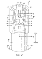
- FIG. 2 there is shown a perspective view, partially in section, of an exemplary embodiment of the connector 19 of FIG. 1 having a self-sealing male connector 20 which in this case is a male Luer connector.
- the male Luer connector includes a housing 40 having a central distally-projecting tubular male body 42 and an outer cuff 52 interconnected with the male body by a base 56 at the proximal end 27 of the male body 42 so as to form a distally-opening cavity 61 configured for receiving a female Luer connector, such as the connector 26 shown in FIG. 3 .
- the male body is formed with an internal flow passage or bore 46 within which a valve element, which in this embodiment comprises a valve plug 70, is slidably installed.
- the valve plug is generally formed with a central lengthwise stem 72 having a distal head 75 configured to sealingly engage the distal end of the flow passage that forms a flow passage opening 21 located at the distal end of the male body so as to selectively prevent fluid flow through the connector.
- At the opposite, proximal end of the valve plug 70 at least one upwardly-turned activation arm 78 is configured so as to project distally into the cavity 61 through an activation opening 58 (shown in FIG. 3 ) formed in the base 56.
- An elastomeric sealing device 90 is configured within the activation opening around the activation arm in order to hold the valve plug in place within the housing and bias the valve plug distally into sealing engagement with the male body's internal flow passage.
- a conventional female Luer connector 94 is formed at the proximal end 27 of the male body 42.
- the female Luer connector includes thread elements 100. It should be appreciated however that a variety of other connectors and devices, such as a shielded blood collection cannula device 95 (shown in FIG. 10 ), may be employed.
- the valve plug 70 remains in its at-rest, flow stop, distal position at which it seals off the flow passage and prevents the unwanted escape of any fluids within the connector 19 and the syringe to which it is mounted ( FIG. 1 ).
- the activation arm 78 projecting distally from the proximal end of the valve plug 70 is shown as extending into the female Luer connector-receiving cavity 61 beyond the elastomeric sealing device 90 so that the distal end 79 of the arm is exposed.
- a female Luer connector 26 for example, that shown in FIG. 3
- the proximal end of the female connector will come into contact with the distal end 79 of the arm.
- proximal movement of the female connector onto the male connector to fully seat will, in turn, proximally shift the valve plug through engagement of the activation arm with the female connector.
- proximal movement of the valve plug against the biasing force of the elastomeric device serves to unseat the valve plug's distal head from the distal end or flow passage opening 21 of the flow passage 46. Because, as shown, the valve plug stem 72 is narrow relative to the flow passage bore, once the male and female connectors are connected and the valve plug has shifted proximally to unseat the head and open the flow passage opening, fluid can flow around the stem and through the connectors.
- the self-sealing male Luer connector 20 closes and prevents flow therethrough when disconnected from a female connector, or the like, while it opens to a flow position and allows flow during connection.
- the male Luer connector is thus configured to be both self sealing and to allow needleless connection to a female Luer connector, thereby protecting both the care giver and the patient from dangerous cross-contamination before, during and after use.
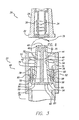
- FIG. 3 there is shown a partial cross-sectional view of the exemplary embodiment of the self-sealing male Luer connector 20 of the connector 19 of FIG. 2 .
- the central lengthwise stem 72 of the valve plug 70 is positioned substantially coaxially within the flow passage 46 and terminates proximally in a linkage 82 defining a horizontal bar 83 on which are mounted one or more activation arms 78 at the respective opposite bar ends 84.
- the cross-section of the valve plug is generally an upside-down capital "T".
- the valve plug may then be formed with two substantially opposite activation arms configured to extend parallel to the stem from opposite ends of the linkage and to be aligned with and project distally through two corresponding activation holes 58 formed in the base 56.
- the forces serving to shift the valve plug proximally are substantially symmetrical and balanced so as to obtain smooth, linear translation of the valve plug and, specifically, of each activation arm within its respective activation opening.
- Each activation opening 58 may be defined by a radially-inwardly projecting annular flange 59 on which the elastomeric device 90 seats.
- the flange is essentially formed by configuring the activation opening inside diameter to be smaller than the transverse dimension of the closed end of the distally-facing cavity 61 ( FIG. 2 ) defined as the difference between the nominal inside diameter of the housing cuff 52 and the outside diameter of the proximal end of the male body 42.
- the elastomeric device serves to bond the valve plug 70 to the housing 40, to seal the activation openings in the housing wall about the activation arms, and to provide a biasing spring force to keep the valve plug seated distally within the flow passage.
- the elastomeric device may consist of an elastomeric sealing material 91 such as Loctite® 3103 ultraviolet cured acrylic deposited within each activation opening while the respective activation arm is in position. Once cured, the elastomeric material has a high bond strength but allows substantial elongation so as to accommodate temporary proximal displacement of the valve plug during use of the male Luer connector. It also acts as a spring to bias the valve plug back to the flow stop position shown in FIG. 3 .
- the flow passage 46 formed through the tubular male body 42 is shown in the exemplary embodiment male Luer connector 20 as having a distally-tapered annular inside surface 47 terminating distally in a radially-inward, proximally-facing nesting shoulder 49 so as to define a central flow passage opening 48 and act as a valve seat.
- the distal head 75 of the valve plug 70 is configured to seat against the shoulder so as to achieve a surface-to-surface seal when the valve plug is forced into contact with the shoulder by a biasing device such as elastomeric device 90.
- the valve plug's stem is configured with an outside diameter that is smaller than the nominal inside diameter of the flow passage so as to provide an annular space through which fluid can flow around the stem when the valve is opened.
- the stem is further formed having a sufficient length to space the valve plug's base 82 away from the proximally-facing surface of the housing wall 56 to provide clearance for the elastomeric device to fully seat about the annular flange 59 of the activation opening and to allow fluid flow around the base through the flow passage.
- the configuration of the housing 40 shown in FIGS. 2 and 3 is well-suited for the injection molding manufacturing process, whereby the housing may be made in a relatively simple two-half mold cavity with a single core pull. Because the design of the housing is particularly suited to injection molding, then, it may be formed from a variety of plastic materials such as polyethylene, polypropylene, polycarbonate, PVC, ABS, acrylic and K-resin. Similarly, the valve plug 70 is also conveniently fabricated using a conventional injection molding process as is known and practiced in the art and thus may also be formed from a wide variety of plastics. As such, the male Luer connector is readily manufacturable with few moving parts.
- the conventional female Luer connector 94 that is disposed at the proximal end of the male connector body and which extends proximally from the male Luer connector's housing 40 is shown in the exemplary embodiment as a separate component having its distal end press-fit within the housing's proximal end.
- the female Luer connector like the housing and the valve plug 70, may be formed through an injection molding process and subsequently installed on the housing using a variety of assembly techniques now known or later developed in the art, including a press- or interference-fit, solvent bonding, or ultrasonic welding.
- the housing is of sufficient length proximal of the housing wall 56 such that the female Luer connector or other medical device can be installed proximally while leaving enough space between the distal end of the female Luer connector and the base 82 of the valve plug to allow the valve plug to translate proximally when the male Luer connector is connected to a patient's IV interface female connector 26 during use for example.
- the distal end 36 of the female Luer connector 94 may be configured to support a compression spring or the like which, when installed within the housing between the female Luer connector 94 and the base of the valve plug 82, may cooperate with the elastomeric device 90 to bias the valve plug distally so as to maintain a bias tending to maintain a seal between the valve plug head 75 and the flow passage distal shoulder 49.
- the female Luer connector 26 of a patient's IV interface 24 ( FIG. 1 ) shown adjacent the distal end of the male Luer connector 20 is generally configured with a tubular barrel 28 having a distally-tapered interior surface 30 formed according to ANSI/AAMI/ISO standard 594.1 for medical connectors.
- the inner surface tapers inward in the distal direction from a larger diameter to a smaller diameter.
- a self sealing piston 34 may be installed within the barrel having a selectively openable opening 35 responsive to compression of the piston upon insertion of a male Luer connector to open the opening and allow fluid flow through the female Luer connector. As will be discussed more fully below regarding FIGS.
- the male body 42 of the self-sealing male Luer connector 20 is formed with a distally-tapered exterior surface 44 that tapers in the distal direction from a larger diameter to a smaller diameter, configured to sealingly engage the tapered inside surface of the female Luer connector when the two connectors are mated.
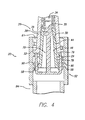
- FIG. 4 there is shown a partial cross-sectional view of the self-sealing male Luer connector 20 with the female Luer connector 26 partially inserted thereon.
- the valve element 75 of the connector 19 remains in the flow stop position.
- the female Luer connector's tubular barrel 28 has been advanced proximally within the cavity 61 onto the male body 42 until the proximally-facing barrel abutment surface 29 has just come into contact with the distal ends 79 of the respective activation arms 78.
- the female Luer connector has not yet shifted the valve plug 70 proximally, so the distal head 75 remains in sealing engagement within the flow passage 46 due to the biasing force of the elastomeric device 90 mounted within the activation openings 58 about the valve plug's activation arms.
- the tubular male body has passed a sufficient distance within the female Luer connector's barrel to begin to form a taper-to-taper surface seal between the male body's outside surface 44 and the barrel's inside surface 30.
- the passage of the distal end of the male body into the barrel has served to compress the self-sealing piston 34 and thereby open the opening 35.
- the male Luer connector is so configured that upon partial connection with a self-sealing female Luer connector, the two connectors begin to seal along their corresponding distally-tapered surfaces and the self-sealing piston is activated before any fluid flow through the male Luer connector is allowed.
- the male Luer connector in accordance with the present invention provides for safe and effective needleless connection to a self sealing female Luer connector with minimized risk of fluid escape by essentially causing the female Luer connector to be activated before the male Luer connector is activated through further proximal movement of the female Luer connector.
- FIG. 5 there is shown a partial cross-sectional view of the female Luer connector 26 fully inserted onto the self-sealing male Luer connector 20.
- the valve plug 70 has shifted proximally with the further proximal movement of the female Luer connector against the biasing force of the elastomeric sealing device 90 to unseat the distal head 75 from the shoulder 49 and allow flow through the flow passage 46, thereby now activating the male Luer connector.
- the valve element is thus in the flow position.
- the elastomeric material 91 comprising the sealing device remains bonded to both the activation arms and the activation openings 58 as it stretches proximally with the proximal movement of the entire valve plug.
- the bond strength of an ultraviolet cured acrylic or the like as the elastomeric material may alone be sufficient to resist the forces applied by the proximal movement of the female Luer connector
- the radially-inward flanges 59 formed about each activation opening provide a seat on which the elastomeric device can anchor, thereby improving the device's strength and its ability to remain installed within the activation openings about the activation arms even under load.
- the fluid will flow through the female Luer connector's piston 34, its opening 35, the central flow passage opening 48 at the distal end of the flow passage 46, through the flow passage itself by passing around the distal head 75 and stem 72 of the valve plug, out the proximal end of the flow passage opening and through the flow openings 86 created by the space between the base 82 of the valve plug and the proximal housing wall 56, and through the proximal female Luer connector 94 into the syringe 22 ( FIG. 1 ).
- the same flow path would be followed in reverse if medicines or other fluids are being dispensed from the syringe into the patient's IV line 25 ( FIG. 1 ).
- the female Luer connector may then simply be disconnected from the male Luer connectors, whereby the respective self-sealing devices would then reseal in the reverse order. That is, as the female Luer connector is withdrawn distally from the male Luer connector, the valve plug will reseal first under the biasing force exerted by the elastomeric device 90 when the female Luer connector reaches the position shown in FIG. 4 .
- the male Luer connector is easy to wipe and keep sanitary, as all engagement surfaces are exposed and easily accessible upon disconnection of the device from the female connector.
- the activation arms 78, and their linkage 82 and 83 thus form a valve element control device, with the arms disposed external to the male connector body adjacent the proximal end of the male connector body and being movable towards the proximal end, to control movement of the valve element to the flow position and being movable toward the distal end to control movement of the valve element to the flow stop position.
- the female Luer connector 26 may be formed on the proximal end of its tubular barrel 28 with external thread elements or portions 32 as is known in the art. Accordingly, the inside surface 53 of the male Luer connector housing 40's cuff 52 may be formed with internal threads 54 configured to threadably engage the female Luer connector's external thread portions and thereby pull and secure the female connector in sealing engagement with the male connector.
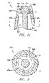
- FIG. 6 there is seen a top view of the male Luer connector 20 of FIG. 2 .
- the use of two activation arms essentially 180 degrees apart is only one of various arrangements possible in accordance with aspects of the present invention.
- FIG. 7 there is shown a bottom view of the male Luer connector of FIG. 2 , with the proximally-projecting female Luer connector 94 ( FIG. 2 ) removed for clarity in illustrating the relevant elements.
- the linkage 82 of the valve plug 70 ( FIG. 3 ) is configured as a substantially linear bar 83 extending symmetrically in opposite directions away from the proximal end of the stem 72 so as to position the respective bar ends 84 substantially beneath the activation openings 58 ( FIG. 3 ) so that the activation arms 78 ( FIG. 3 ) extending distally away from the bar ends can freely translate within the activation openings.
- the flow passage 46 is unhindered proximally by the base, allowing flow around the base with the valve plug in any position within the male body 42 ( FIGS. 2-6 ), while the far, distal end of the flow passage is sealed off by the distal head 75 with the valve plug in the distally-biased position shown.
- the plug will be inserted from the bottom as in FIG. 7 and then the activation arms will be bonded in place within the activation openings by inserting the elastomeric device 90 in and about the openings so as to essentially pot the valve plug in position within the valve with the distal head sealingly seated in the distal end of the flow passage.
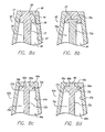
- FIGS. 8a-8e there are shown enlarged partial cross-sectional views of various exemplary embodiments of the configuration of the distal end of the male body 42's flow passage 46 and the corresponding configuration of the valve plug 70's stem 72 and distal head 75 so as to selectively seal within the flow passage as discussed above. It is to be understood that these embodiments are exemplary only and that a variety of sealing arrangements are possible.
- FIG. 8a there is seen the exemplary configuration of the male Luer connector 20 shown in FIGS. 2-7 wherein the flow passage has a distally-tapered interior surface 47 that terminates distally in a in a radially-inward, proximally-facing nesting shoulder 49.
- the shoulder may be configured as a proximally-facing first frusto-conical surface 50.
- the distal head is configured with a distally-facing second frusto-conical surface 76 so as to correspond to the first frusto-conical surface.
- the valve plug is formed as a unitary structure from a single material.
- the stem and head may both be injection molded from a semirigid thermoplastic such that the stem has the necessary mechanical integrity to transmit the force exerted by the elastomeric device 90 ( FIGS.
- FIG. 8b there is shown a male body 42 and valve plug 70a quite similar to that of FIG. 8a , with the exception that the stem 72a and head 75a are not formed of one material in a unitary construction. Rather, the stem is formed again of a rigid or semi-rigid material but is configured at its distal end with a distal flange 73. The head is then overmolded onto the distal end of the stem about the distal flange. In this way, it will be appreciated that the head may be made of a resilient, flexible material so as to seal within the distal end of the flow passage 46.
- the material of the head may be selected from a number of medical grade silicon rubbers, thermoplastic elastomers, and thermoplastic vulcanates.
- the head may be slightly oversized relative to the distal end of the flow passage so as to slightly compress the head when the valve plug is biased distally by the elastomeric sealing device 90 ( FIGS. 2 and 3 ) and thereby insure a positive seal when the male Luer connector is disconnected or is otherwise not in use.
- a resilient head could be molded in a separate operation and mounted onto the valve stem using other assembly techniques now know or later developed in the art, such as solvent bonding or snap- or press-fit.
- FIGS. 8c and 8d an alternative configuration for the radially-inwardly extending nesting shoulder 49a of the tubular male body 42a is shown wherein the shoulder is generally an annular flange that is perpendicular to the body's axis so as to form a squared proximally-facing sealing surface 50a.
- the annular flange defines a central flow passage opening 48a through which fluids can selectively pass from a female Luer connector 26 ( FIG. 5 ) into the male Luer connector's flow passage 46a.
- the valve plug 70b is shown as having a generally "T"-shaped cross-section formed by a vertical stem 72b and a horizontal distal head 75b.
- the distally-facing head sealing surface 76b is brought into surface-to-surface contact with the shoulder's proximally-facing sealing surface so as to create a face seal and prevent fluid flow through the connector. Then, when the valve as activated upon connection to a female Luer connector as described above and the distal head is shifted proximally, it will be appreciated that the straight-walled side surface 77b again allows fluid flow between the head and the distally-tapered interior surface 47a of the flow passage.
- the distal head 75c may be configured with a substantially planar, distally-facing sealing surface 76c configured to create a face seal against the nesting shoulder 49a's proximally-facing sealing surface 50a when the valve plug 70c is biased distally within the flow passage 46a.
- a distally-projecting head plug 98 may be configured on the head's distally-facing surface so as to effectively plug and seal within the central flow passage opening 48a. In this way, more surface-to-surface engagement is provided to further effectuate a positive seal between the valve plug head and the distal end of the flow passage.
- the distal end of the head plug may be rounded to facilitate centering and seating the head plug within the flow passage opening.
- the side surface 77c of the head may be proximally-tapered or radiused inwardly to provide further clearance between the head and the interior surface 47a of the flow passage when the valve is activated.
- FIG. 8e there is shown an alternative configuration of the tubular male body 42b in which the flow passage 46b is formed having a substantially straight-walled interior surface 47b parallel with the flow passage's central axis.
- the flow passage again terminates distally in a radially-inwardly-projecting, distally-tapered nesting shoulder 49b defining a central flow passage opening 48b and a proximally-facing first frusto-conical surface 50b. Due to the non-tapered interior surface of the flow passage, it will be appreciated by those skilled in the art that the previous exemplary valve plug and head configurations will not effectively open the flow passage when the valve plug is shifted proximally upon connection to a female Luer connector 26 ( FIG. 5 ).
- the distal head 75d of the exemplary embodiment of FIG. 8e is configured with a central solid portion having lengthwise ribs 99 spaced thereabout to allow for fluid communication around the head once the distal end of the head has unseated from the distal end of the flow passage.
- the central portion of the head is formed distally with a distally-facing second frusto-conical surface configured to sealingly engage the shoulder's first frusto-conical surface when the valve plug is biased distally within the flow passage, much like the sealing engagement of the exemplary embodiments of FIGS. 8a and 8b . Then, when the valve plug is shifted proximally during connection with a female Luer connector, the first and second frusto-conical surfaces are disengaged to allow flow through the central flow passage opening into the flow passage.
- fluid flow can continue through the flow passage 46b around the valve plug's distal head 75d by passing about the head's solid portion between the circumferentially spaced-apart ribs 99 and then around the narrowed stem 72d and on through the connector as described previously.
- the ribs serve as spacers to space the solid central portion of the distal head away from the interior surface 47b of the flow passage, thereby allowing fluid flow around the head.
- the ribs further serve to keep the stem and head centered within the flow passage as the valve plug 70d translates axially therein during use of the male Luer connector. It is noted that the taper-to-taper engagement between the distal head and the shoulder 49b ( FIG.
- valve plug 8e can alone serve to center the head as it seats in the distal end of the flow passage so as to effectively close the flow passage opening and that this function in combination with the stiffness of the stem may allow for the activation of the valve within a straight-walled flow passage without the use of the ribbed spacers.
- FIGS. 8a-8e are merely illustrative of selectively sealable arrangements for the respective engaging components that are possible and are in no way limiting of the scope of the present invention.
- the exemplary embodiment male Luer connectors of FIGS. 8c-8e may also be configured with the valve plug having a single, unitary construction or with the stem of a rigid or semi-rigid plastic and a resilient head overmolded or otherwise mounted onto the stem's distal end.
- FIG. 10 there is shown an alternative embodiment of a connector 19a having a male Luer connector 20a having a blood collection device 95 mounted opposite the housing 40.
- the blood collection device which is known and used in the art, includes a proximally-extending needle cannula 97 and a shield 96 mounted about the needle so as to protect care givers and patients from accidental needle punctures.
- the connector's male body 42 may be connected to the female Luer connector 26 of a patient's IV interface 24 ( FIG. 1 ), as discussed above, to activate the internal valve plug 70 ( FIG. 2 ) and create a needle-free flow path between the patient's IV line 25 ( FIG. 1 ) and the needle through the male Luer connector.
- a resilient boot (not shown) over the needle prevents the flow of fluid through the needle until a vacuumized blood collection vial with septum (not shown) is inserted within the blood collection device shield to push the boot up the needle while the needle then penetrates the septum to allow fluid to flow therethrough into the vial.
- the vial When the vial is full, it may be removed from the blood collection device and another installed therein until the desired quantity of blood has been withdrawn. Then, the male connector may simply be disconnected from the female connector on the patient's IV line and discarded.
- the self-sealing internal valve plug operably installed within the male connector serves to safely and easily connect to and disconnect from the female Luer connector of a patient's IV line for the effective and controlled administration and/or withdrawal of fluids.
- the male Luer connector is well-suited for connection to a syringe or other device used to transfer fluids to and from a patient without compromising the patient's or the care giver's safety. While particular forms of the invention have been illustrated and described, it will also be apparent to those skilled in the art that various modifications can be made without departing from the scope of the invention. Accordingly, it is not intended that the invention be limited except by the appended claims.
Landscapes
- Health & Medical Sciences (AREA)
- Life Sciences & Earth Sciences (AREA)
- Heart & Thoracic Surgery (AREA)
- Engineering & Computer Science (AREA)
- Animal Behavior & Ethology (AREA)
- Hematology (AREA)
- Veterinary Medicine (AREA)
- Biomedical Technology (AREA)
- Public Health (AREA)
- General Health & Medical Sciences (AREA)
- Molecular Biology (AREA)
- Surgery (AREA)
- Pathology (AREA)
- Medical Informatics (AREA)
- Physics & Mathematics (AREA)
- Biophysics (AREA)
- Pulmonology (AREA)
- Anesthesiology (AREA)
- Manufacturing & Machinery (AREA)
- Infusion, Injection, And Reservoir Apparatuses (AREA)
- Quick-Acting Or Multi-Walled Pipe Joints (AREA)
- Feeding And Controlling Fuel (AREA)
- Water Treatment By Sorption (AREA)
- External Artificial Organs (AREA)
- Replacement Of Web Rolls (AREA)
- Medical Preparation Storing Or Oral Administration Devices (AREA)
- Sealing Devices (AREA)
Claims (19)
- Verbinder, der folgendes umfasst:einen männlichen Verbinderkörper (42) mit einem proximalen Ende und einem distalen Ende mit einer Strömungskanalöffnung an dem distalen Ende (21) und mit einem internen Strömungskanal (46), der mit der Strömungskanalöffnung (21) verbunden ist;ein Ventilelement (70), das in dem männlichen Verbinderkörper (42) in dem internen Strömungskanal (46) angeordnet und beweglich ist zwischen einer Strömungsunterbrechungsposition, an der das Ventilelement (70) die Strömungskanalöffnung (21) in Bezug auf Fluidströmung abdichtet, und einer Strömungsposition, an der das Ventilelement (70) von der Strömungskanalöffnung (21) entfernt ist, wodurch eine Strömung durch die Öffnung ermöglicht wird; undeine Ventilelement-Regelungsvorrichtung (78), die außerhalb des männlichen Verbinderkörpers (42) angrenzend an das proximale Ende des männlichen Verbinderkörpers angeordnet und in Richtung des proximalen Endes beweglich ist, um die Bewegung des Ventilelements (70) an die Strömungsposition zu regeln, und wobei die Vorrichtung in Richtung des distalen Endes beweglich ist, um die Bewegung des Ventilelements (70) an die Strömungsunterbrechungsposition zu regeln;wobei der Verbinder dadurch gekennzeichnet ist, dass er ferner eine Basis (56) außerhalb des männlichen Verbinderkörpers (42) umfasst, die an dem proximalen Ende des männlichen Verbinderkörpers auswärts vorsteht, wobei die Ventilelement-Regelungsvorrichtung (78) mindestens einen aufwärts gedrehten Aktivierungsarm (78) an dem proximalen Ende des Ventilelements (70) umfasst, der so konfiguriert ist, dass er sich durch eine in der Basis (56) ausgebildete Aktivierungsöffnung (58) in Richtung des distalen Endes erstreckt.
- Verbinder nach Anspruch 1, wobei das Ventilelement (70) die Strömungskanalöffnung (21) in Bezug auf den internen Strömungskanal (46) in dem männlichen Verbinderkörper (42) abdichtet.
- Verbinder nach Anspruch 1, wobei dieser ferner eine Vorbelastungsvorrichtung (90) umfasst, die an der Basis (56) angeordnet ist, um die Ventilelement-Regelungsvorrichtung (78) zur Regelung des Ventilelements (70) an die Strömungsunterbrechungsposition zu regeln.
- Verbinder nach Anspruch 3, wobei die Vorbelastungsvorrichtung (90) eine Feder umfasst, die so angeordnet ist, das sie eine Vorbelastungskraft an die Ventilelement-Regelungsvorrichtung (78) vorsieht, um das Ventilelement (70) so zu regeln, dass sich dieses an die Strömungsunterbrechungsposition bewegt.
- Verbinder nach Anspruch 3, wobei die Vorbelastungsvorrichtung (90) ein elastomeres Material umfasst, das sowohl mit der Basis (56) als auch mit der Ventilelement-Regelungsvorrichtung (78) verbunden ist.
- Verbinder nach Anspruch 5, wobei das elastomere Material der Vorbelastungsvorrichtung (90) die Basis (56) auch dort, wo sich die Ventilelement-Regelungsvorrichtung (78) durch die Basis erstreckt, gegen eine Fluidströmung durch die Basis (56) abdichtet.
- Verbinder nach Anspruch 1, wobei der männliche Verbinderkörper (42) die Form eines äußeren männlichen, konischen Luer-Verbinders aufweist.
- Verbinder nach Anspruch 1, wobei dieser ferner folgendes umfasst:eine äußere Manschette (52), die entlang der Basis (56) mit dem männlichen Verbinderkörper (42) verbunden ist, so dass eine sich distal öffnende Vertiefung gebildet wird; wobeidie Basis (56) mit mindestens einer Aktivierungsöffnung (58) ausgebildet ist;wobei das Ventilelement (70) einen zentralen Schaft (72) umfasst, der mit einem distalen Kopf (75) konfiguriert ist, um den Strömungskanal selektiv abzudichten; undeine elastomere Vorrichtung (90), die abdichtend in der Aktivierungsöffnung (58) um den Aktivierungsarm (78) konfiguriert ist, um das Ventilelement (70) an der Verwendungsposition innerhalb des männlichen Verbinderkörpers (42) zu sichern und das Ventilelement (70) effektiv distal vorzubelasten, um es zu bewirken, dass der distale Kopf (75) den Strömungskanal (21) abdichtet, wobei die elastomere Vorrichtung (90) auf die Aufnahme einer röhrenförmigen Trommel innerhalb der Vertiefung so anspricht, dass sich das Ventilelement (70) proximal verschieben kann, wenn die röhrenförmige Trommel mit dem Aktivierungsarm (78) eingreift, um den Strömungskanal zu öffnen und es zu ermöglichen, dass Fluid durch den männlichen Luer-Verbinder strömt.
- Verbinder nach Anspruch 8, wobei der Strömungskanal mit einer ringförmigen inneren Oberfläche ausgebildet ist, die einen nominalen Strömungskanaldurchmesser definiert, wobei die Strömungskanalöffnung (21) einen Strömungskanalöffnungsdurchmesser aufweist, der kleiner ist als der Strömungskanaldurchmesser, so dass eine proximal ausgerichtete Verschachtelungsschulter ausgebildet wird; und wobei der distale Kopf (75) so konfiguriert ist, dass er an der Verschachtelungsschulter abdichtet, wenn das Ventilelement (70) distal innerhalb des männlichen Verbinderkörpers (42) vorbelastet ist.
- Verbinder nach Anspruch 9, wobei:die Verschachtelungsschulter als eine radial einwärts angewinkelte erste kegelstumpfförmige Oberfläche konfiguriert ist; undder distale Kopf (75) mit einer entsprechenden radial einwärts angewinkelten zweiten kegelstumpfförmigen Oberfläche ausgebildet ist, die so konfiguriert ist, dass sie abdichtend mit der ersten kegelstumpfförmigen Oberfläche eingreift, wenn das Ventilelement (70) distal innerhalb des männlichen Verbinderkörpers (42) vorbelastet wird.
- Verbinder nach Anspruch 9, wobei die ringförmige innere Oberfläche distal konisch ist.
- Verbinder nach Anspruch 9, wobei:die ringförmige innere Oberfläche geradwandig ist; undder distale Kopf (75) mit der Länge nach, mit Zwischenabständen angeordneten, sich radial auswärts erstreckenden Rippen konfiguriert ist, um den Kopf mit Zwischenabstand zu der inneren Oberfläche anzuordnen und um dazwischen einen Strömungskanal bereitzustellen.
- Verbinder nach Anspruch 8, wobei das Ventilelement (70) an dessen proximalen Ende mit einer Ventilelementbasis ausgebildet ist, welche den Schaft und den Aktivierungsarm miteinander verbindet" wobei der Schaft (72) eine ausreichende Länge aufweist, so dass bei einer proximalen Verschiebung des Ventilelements (70) innerhalb des männlichen Verbinderkörpers (42) das Ventilelement räumlich von dem männlichen Verbinderkörperwand (52) getrennt wird, so dass zumindest eine Strömungsöffnung zwischen der Ventilelementbasis und der Gehäusewand gebildet wird.
- Verbinder nach Anspruch 13, wobei:die Ventilelementbasis eine im Wesentlichen planare Stange mit mindestens einem Stangenende definiert und im Wesentlichen senkrecht zu dem Schaft (72) ist; undder Aktivierungsarm (78) an dem Stangenende im Wesentlichen parallel zu dem Schaft (72) ausgebildet ist, so dass er distal durch die Aktivierungsöffnung (58) in die Vertiefung vorsteht und darin geradlinig verschoben wird, wenn das Ventilelement (70) proximal verschoben wird, nachdem in die proximale Richtung eine Kraft auf den Aktivierungsarm (78) ausgeübt worden ist.
- Verbinder nach Anspruch 9, wobei der Schaft (72) eine ringförmige äußere Oberfläche aufweist, die einen Schaftdurchmesser definiert, der kleiner ist als der Strömungskanaldurchmesser, um eine Strömung um den Schaft zwischen der ringförmigen inneren Oberfläche des Strömungskanals und der ringförmigen äußeren Oberfläche des Schafts (72) zu ermöglichen, wenn das Ventilelement (70) proximal verschoben wird, nachdem auf den Aktivierungsarm (78) in die proximale Richtung eine Kraft ausgeübt worden ist.
- Verbinder nach Anspruch 8, wobei das Ventilelement proximal mit mindestens einer Strömungsöffnung ausgebildet ist, um eine Fluidströmung dort herum zu ermöglichen, wenn das Ventilelement proximal verschoben wird, nachdem auf den Aktivierungsarm (78) eine Kraft in die proximale Richtung ausgeübt worden ist.
- Verbinder nach Anspruch 8, wobei es sich bei der elastomeren Vorrichtung um ein elastomeres Dichtungsmaterial handelt, das in der Aktivierungsöffnung (58) um den Aktivierungsarm (78) verbunden ist.
- Verbinder nach Anspruch 17, wobei:die Aktivierungsöffnung (58) mit einem radial einwärts vorstehenden ringförmigen Flansch ausgebildet ist, der einen Aktivierungsöffnungs-Innendurchmesser definiert; unddie elastomere Vorrichtung den Flansch einkapselt, so dass die elastomere Vorrichtung innerhalb der Aktivierungsöffnung verankert wird.
- Verbinder nach Anspruch 8, wobei der Aktivierungsarm (78) distal in einer distal ausgerichteten Armanstoßoberfläche endet, die so konfiguriert ist, dass sie die Kraft aufnimmt, die in die proximale Richtung ausgeübt wird, um dadurch das Ventilelement (70) proximal zu verschieben.
Priority Applications (2)
| Application Number | Priority Date | Filing Date | Title |
|---|---|---|---|
| EP10011524A EP2269686B1 (de) | 2002-12-31 | 2003-12-19 | Selbstdichtender männlicher Luerverbinder mit vorgespanntem Ventilkörper |
| CY20111100780T CY1112408T1 (el) | 2002-12-31 | 2011-08-12 | Αυτο-στεγανοποιουμενος αρσενικος συνδεσμος luer με εκτρεπομενη βαλβιδα-βυσμα |
Applications Claiming Priority (3)
| Application Number | Priority Date | Filing Date | Title |
|---|---|---|---|
| US335242 | 2002-12-31 | ||
| US10/335,242 US7140592B2 (en) | 2002-12-31 | 2002-12-31 | Self-sealing male Luer connector with biased valve plug |
| PCT/US2003/040966 WO2004060474A1 (en) | 2002-12-31 | 2003-12-19 | Self-sealing male luer connector with biased valve plug |
Related Child Applications (1)
| Application Number | Title | Priority Date | Filing Date |
|---|---|---|---|
| EP10011524.5 Division-Into | 2010-09-29 |
Publications (2)
| Publication Number | Publication Date |
|---|---|
| EP1578478A1 EP1578478A1 (de) | 2005-09-28 |
| EP1578478B1 true EP1578478B1 (de) | 2011-06-15 |
Family
ID=32655297
Family Applications (2)
| Application Number | Title | Priority Date | Filing Date |
|---|---|---|---|
| EP10011524A Expired - Lifetime EP2269686B1 (de) | 2002-12-31 | 2003-12-19 | Selbstdichtender männlicher Luerverbinder mit vorgespanntem Ventilkörper |
| EP03814909A Expired - Lifetime EP1578478B1 (de) | 2002-12-31 | 2003-12-19 | Selbstdichtender männlicher luer-verbinder mit vorbelastetem ventilstopfen |
Family Applications Before (1)
| Application Number | Title | Priority Date | Filing Date |
|---|---|---|---|
| EP10011524A Expired - Lifetime EP2269686B1 (de) | 2002-12-31 | 2003-12-19 | Selbstdichtender männlicher Luerverbinder mit vorgespanntem Ventilkörper |
Country Status (16)
| Country | Link |
|---|---|
| US (2) | US7140592B2 (de) |
| EP (2) | EP2269686B1 (de) |
| JP (1) | JP4738815B2 (de) |
| CN (1) | CN100475286C (de) |
| AT (2) | ATE547146T1 (de) |
| AU (1) | AU2003300270B2 (de) |
| CA (1) | CA2511971C (de) |
| CY (1) | CY1112408T1 (de) |
| DK (1) | DK1578478T3 (de) |
| ES (2) | ES2381463T3 (de) |
| NO (1) | NO20053319L (de) |
| NZ (1) | NZ540995A (de) |
| PL (2) | PL209774B1 (de) |
| PT (1) | PT1578478E (de) |
| WO (1) | WO2004060474A1 (de) |
| ZA (1) | ZA200505228B (de) |
Cited By (1)
| Publication number | Priority date | Publication date | Assignee | Title |
|---|---|---|---|---|
| US8628516B2 (en) | 2009-03-22 | 2014-01-14 | Elcam Medical Agricultural Cooperative Association Ltd. | Closed male luer connector |
Families Citing this family (212)
| Publication number | Priority date | Publication date | Assignee | Title |
|---|---|---|---|---|
| US6695817B1 (en) | 2000-07-11 | 2004-02-24 | Icu Medical, Inc. | Medical valve with positive flow characteristics |
| US7040598B2 (en) * | 2003-05-14 | 2006-05-09 | Cardinal Health 303, Inc. | Self-sealing male connector |
| US7634558B1 (en) | 2003-09-22 | 2009-12-15 | Sprint Spectrum L.P. | Method and system for updating network presence records at a rate dependent on network load |
| AU2004293815B2 (en) | 2003-11-20 | 2010-07-22 | The Henry M. Jackson Foundation For The Advancement Of Military Medicine, Inc. | Portable hand pump for evacuation of fluids |
| US20050154368A1 (en) * | 2003-11-21 | 2005-07-14 | Vasogen Ireland Limited | Medical material handling systems |
| HK1077154A2 (en) | 2003-12-30 | 2006-02-03 | Icu Medical, Inc. | Valve assembly |
| US7600530B2 (en) | 2004-08-09 | 2009-10-13 | Medegen, Inc. | Connector with check valve and method of use |
| US10478607B2 (en) | 2004-08-09 | 2019-11-19 | Carefusion 303, Inc. | Connector for transferring fluid and method of use |
| US7306566B2 (en) * | 2004-09-15 | 2007-12-11 | Cardinal Health 303, Inc. | Needle free blood collection device with male connector valve |
| US20060058734A1 (en) * | 2004-09-15 | 2006-03-16 | Phillips John C | Self-sealing male Luer connector with molded elastomeric tip |
| US8337475B2 (en) * | 2004-10-12 | 2012-12-25 | C. R. Bard, Inc. | Corporeal drainage system |
| CA2586115C (en) | 2004-11-05 | 2013-04-23 | Icu Medical, Inc. | Medical connector for having high flow rate characteristics |
| US7645274B2 (en) * | 2004-12-10 | 2010-01-12 | Cardinal Health 303, Inc. | Self-sealing male luer connector with multiple seats |
| US7651481B2 (en) * | 2004-12-30 | 2010-01-26 | CareFusion 303 Inc. | Self-sealing male connector device with collapsible body |
| PL1848913T3 (pl) * | 2005-02-14 | 2013-12-31 | Borla Ind | Zaworowe złącze płynowe |
| US20060270997A1 (en) * | 2005-05-19 | 2006-11-30 | Vasogen Ireland Limited | Permission-based material dispenser |
| ITMO20050141A1 (it) * | 2005-06-09 | 2006-12-10 | Aries S R L | Dispositivo di chiusura per contenitori o linee di somministrazione di fluidi medicinali o fermaceutici. |
| DE102005026986A1 (de) † | 2005-06-10 | 2006-12-14 | Robert Bosch Gmbh | Vorrichtung zum Befüllen und Verschließen von Behältnissen |
| US7448653B2 (en) | 2005-06-10 | 2008-11-11 | Value Plastics, Inc. | Female connector for releasable coupling with a male connector defining a fluid conduit |
| US7998134B2 (en) | 2007-05-16 | 2011-08-16 | Icu Medical, Inc. | Medical connector |
| US7803140B2 (en) | 2005-07-06 | 2010-09-28 | Icu Medical, Inc. | Medical connector with closeable male luer |
| ITTO20050515A1 (it) * | 2005-07-25 | 2007-01-26 | Borla Ind | Connettore valvolare medicale |
| US8177772B2 (en) | 2005-09-26 | 2012-05-15 | C. R. Bard, Inc. | Catheter connection systems |
| JP2007143813A (ja) * | 2005-11-28 | 2007-06-14 | Nippon Sherwood Medical Industries Ltd | 医療用活栓 |
| AU2006331039B2 (en) * | 2005-12-28 | 2012-01-12 | Cardinal Health 529, Llc | Male luer connector |
| US7766897B2 (en) * | 2006-01-02 | 2010-08-03 | Carefusion 303, Inc. | Protective priming cap for self-sealing male Luer valve |
| US7806139B2 (en) | 2006-01-20 | 2010-10-05 | Value Plastics, Inc. | Fluid conduit coupling assembly having male and female couplers with integral valves |
| JP5161457B2 (ja) * | 2006-04-03 | 2013-03-13 | 日本コヴィディエン株式会社 | 雄ルアーコネクター |
| EP2526920B8 (de) | 2006-05-25 | 2015-08-26 | Bayer Healthcare LLC | Rekonstitutionsvorrichtung |
| US8292875B2 (en) * | 2006-09-12 | 2012-10-23 | Clay Kennard | Fluid delivery device |
| US8257286B2 (en) | 2006-09-21 | 2012-09-04 | Tyco Healthcare Group Lp | Safety connector apparatus |
| US8221363B2 (en) | 2006-10-18 | 2012-07-17 | Baxter Healthcare S.A. | Luer activated device with valve element under tension |
| US7981090B2 (en) | 2006-10-18 | 2011-07-19 | Baxter International Inc. | Luer activated device |
| US7753338B2 (en) | 2006-10-23 | 2010-07-13 | Baxter International Inc. | Luer activated device with minimal fluid displacement |
| JP5015258B2 (ja) | 2006-10-25 | 2012-08-29 | アイシーユー・メディカル・インコーポレーテッド | 医療用コネクタ |
| JP4959350B2 (ja) * | 2007-01-19 | 2012-06-20 | 日本コヴィディエン株式会社 | 雄ルアーコネクター |
| US9149573B2 (en) | 2007-03-16 | 2015-10-06 | Smiths Medical Asd, Inc. | Blunt cannula for accessing a slit septum |
| USD571006S1 (en) | 2007-03-23 | 2008-06-10 | Smiths Medical Asd, Inc. | Oval tapering blunt cannula proximal portion |
| USD571464S1 (en) * | 2007-03-23 | 2008-06-17 | Smiths Medical Asd, Inc. | Knife edge tapering blunt cannula proximal portion |
| US8006953B2 (en) * | 2007-05-17 | 2011-08-30 | Lavon Bennett | Luer hub connector |
| US8603029B2 (en) * | 2007-10-10 | 2013-12-10 | Hospi Corporation | Apparatuses and methods for medication administration |
| ITTO20070141U1 (it) * | 2007-11-14 | 2009-05-15 | Borla Ind | Siringa |
| USD654573S1 (en) | 2007-11-19 | 2012-02-21 | Value Plastics, Inc. | Female quick connect fitting |
| EP2259839B1 (de) * | 2008-03-04 | 2015-12-23 | Infusion Innovations, Inc. | Vorrichtungen, anordnungen und verfahren zur kontrolle des flüssigkeitsflusses |
| US8257287B2 (en) | 2008-03-20 | 2012-09-04 | Tyco Healthcare Group Lp | Safety connector assembly |
| US9408971B2 (en) * | 2008-03-31 | 2016-08-09 | Covidien Lp | Self-capping syringe assembly with one-way valve |
| EP2280753B1 (de) | 2008-05-14 | 2017-07-19 | J&J Solutions, Inc. | Systeme und verfahren für sicheren medikamententransport |
| US20090306544A1 (en) | 2008-06-09 | 2009-12-10 | Ho-Kin Ng | Instillation/aspiration device |
| US20090301480A1 (en) * | 2008-06-09 | 2009-12-10 | Mamdouh Elsakka | Diagnostic sample collection system and method of use |
| ES2371143T3 (es) * | 2008-06-30 | 2011-12-27 | Tyco Healthcare Group Lp | Adaptador discriminatorio de punta oral. |
| US8235426B2 (en) | 2008-07-03 | 2012-08-07 | Nordson Corporation | Latch assembly for joining two conduits |
| US8060089B1 (en) | 2008-09-22 | 2011-11-15 | Sprint Spectrum L.P. | Paging success rate control mechanism |
| WO2013116670A1 (en) | 2012-02-01 | 2013-08-08 | Hospi Corporation | Valved enteral administration assembly |
| US9078992B2 (en) | 2008-10-27 | 2015-07-14 | Pursuit Vascular, Inc. | Medical device for applying antimicrobial to proximal end of catheter |
| US8679090B2 (en) * | 2008-12-19 | 2014-03-25 | Icu Medical, Inc. | Medical connector with closeable luer connector |
| US9168366B2 (en) | 2008-12-19 | 2015-10-27 | Icu Medical, Inc. | Medical connector with closeable luer connector |
| JP5684732B2 (ja) | 2009-02-07 | 2015-03-18 | メリット・メディカル・システムズ・インコーポレーテッド | バルブ付コネクタ |
| US8523826B2 (en) * | 2009-02-13 | 2013-09-03 | Cytyc Corporation | Luer-type needle-free valve fitting with bypass |
| US8454579B2 (en) | 2009-03-25 | 2013-06-04 | Icu Medical, Inc. | Medical connector with automatic valves and volume regulator |
| US8182452B2 (en) * | 2009-04-06 | 2012-05-22 | Carefusion 303, Inc. | Closed male luer device for use with needleless access devices |
| DE102009024575A1 (de) * | 2009-04-23 | 2010-12-23 | Fresenius Medical Care Deutschland Gmbh | Verbindungseinrichtung und Verfahren zum Konnektieren wenigstens zweier fluidführender medizinitechnischer Systeme, sowie medizintechnische Vorrichtung |
| US8057095B2 (en) | 2009-04-23 | 2011-11-15 | Medtronic, Inc. | Multiple use temperature monitor adapter, system and method of using same |
| EP2251061B1 (de) * | 2009-05-11 | 2018-04-18 | Kpr U.S., Llc | Diskriminationsflüssigkeitsverbindungssystem |
| USD655393S1 (en) | 2009-06-23 | 2012-03-06 | Value Plastics, Inc. | Multi-port valve |
| USD616985S1 (en) * | 2009-06-26 | 2010-06-01 | Abbott Point Of Care Inc. | Dispensing tip |
| USD627065S1 (en) * | 2009-06-26 | 2010-11-09 | Abbott Point Of Care Inc. | Dispensing tip and cap |
| IL201323A0 (en) | 2009-10-01 | 2010-05-31 | Medimop Medical Projects Ltd | Fluid transfer device for assembling a vial with pre-attached female connector |
| IL202070A0 (en) | 2009-11-12 | 2010-06-16 | Medimop Medical Projects Ltd | Inline liquid drug medical device |
| IL202069A0 (en) | 2009-11-12 | 2010-06-16 | Medimop Medical Projects Ltd | Fluid transfer device with sealing arrangement |
| US9388929B2 (en) | 2009-12-09 | 2016-07-12 | Nordson Corporation | Male bayonet connector |
| US10711930B2 (en) | 2009-12-09 | 2020-07-14 | Nordson Corporation | Releasable connection assembly |
| USD783815S1 (en) | 2009-12-09 | 2017-04-11 | General Electric Company | Male dual lumen bayonet connector |
| USD650478S1 (en) | 2009-12-23 | 2011-12-13 | Value Plastics, Inc. | Female dual lumen connector |
| USD649240S1 (en) | 2009-12-09 | 2011-11-22 | Value Plastics, Inc. | Male dual lumen bayonet connector |
| WO2011079225A1 (en) | 2009-12-23 | 2011-06-30 | Value Plastics, Inc. | Fluid connector latches with profile lead-ins |
| SG181932A1 (en) | 2009-12-23 | 2012-07-30 | Nordson Corp | Button latch with integrally molded cantilever springs |
| JP5416848B2 (ja) | 2010-02-24 | 2014-02-12 | メディモップ・メディカル・プロジェクツ・リミテッド | 通気構造体を有する流体移送アセンブリ |
| JP5709905B2 (ja) | 2010-02-24 | 2015-04-30 | メディモップ・メディカル・プロジェクツ・リミテッド | ベント付きバイアルアダプタを含む液剤移送デバイス |
| USD644731S1 (en) | 2010-03-23 | 2011-09-06 | Icu Medical, Inc. | Medical connector |
| US8298196B1 (en) * | 2010-03-24 | 2012-10-30 | Mansour George M | Needleless access connector and method of use |
| AU2011248364B8 (en) | 2010-05-06 | 2014-06-26 | Icu Medical, Inc. | Medical connector with closeable luer connector |
| US8758306B2 (en) | 2010-05-17 | 2014-06-24 | Icu Medical, Inc. | Medical connectors and methods of use |
| EP2575734B1 (de) | 2010-05-27 | 2017-04-19 | J&J Solutions, Inc. | Geschlossenes flüssigkeitstransfersystem |
| JP5562130B2 (ja) | 2010-06-14 | 2014-07-30 | 日本コヴィディエン株式会社 | 雄コネクター及びこれを備えた輸液ラインの接続装置 |
| EP2407103B1 (de) * | 2010-07-14 | 2013-11-27 | General Electric Company | Flüssigkeitsverbindung zum Verringern einer Flüssigkeitsmenge in einer Verbindung |
| EP2603254A4 (de) * | 2010-08-12 | 2016-08-24 | Boston Scient Ltd | Infusionsflusssystem und flüssigkeitskupplung |
| IL209290A0 (en) | 2010-11-14 | 2011-01-31 | Medimop Medical Projects Ltd | Inline liquid drug medical device having rotary flow control member |
| USD652511S1 (en) | 2011-02-11 | 2012-01-17 | Value Plastics, Inc. | Female body of connector for fluid tubing |
| USD663022S1 (en) | 2011-02-11 | 2012-07-03 | Nordson Corporation | Male body of connector for fluid tubing |
| USD652510S1 (en) | 2011-02-11 | 2012-01-17 | Value Plastics, Inc. | Connector for fluid tubing |
| IL212420A0 (en) | 2011-04-17 | 2011-06-30 | Medimop Medical Projects Ltd | Liquid drug transfer assembly |
| US9005170B2 (en) * | 2011-04-18 | 2015-04-14 | Gale H. Thorne, Jr. | Protection against spill and syringe related contamination |
| US20120261027A1 (en) | 2011-04-18 | 2012-10-18 | Py Daniel C | Needle with closure and method |
| DE102011075029A1 (de) * | 2011-04-29 | 2012-10-31 | Smiths Medical Deutschland Gmbh | Fluidhandhabungsvorrichtung mit Dichtvorrichtung |
| US9950114B2 (en) | 2011-05-13 | 2018-04-24 | Thorne Consulting For International Property, Llc | Dual-chamber syringe and associated connecting systems |
| US9295827B2 (en) | 2013-04-29 | 2016-03-29 | Gale Harrison Thorne | Twisted slit valve |
| WO2012162259A2 (en) | 2011-05-20 | 2012-11-29 | Excelsior Medical Corporation | Caps for cannula access devices |
| EP3714932A1 (de) | 2011-07-12 | 2020-09-30 | ICU Medical, Inc. | Vorrichtung zur verabreichung eines antimikrobiellen mittels in einen transdermalen katheter |
| US8974437B2 (en) | 2011-07-28 | 2015-03-10 | Applied Medical Technology, Inc. | Coupling for medical fluids |
| USD699841S1 (en) | 2011-07-29 | 2014-02-18 | Nordson Corporation | Female body of connector for fluid tubing |
| USD699840S1 (en) | 2011-07-29 | 2014-02-18 | Nordson Corporation | Male body of connector for fluid tubing |
| USD698440S1 (en) | 2011-07-29 | 2014-01-28 | Nordson Corporation | Connector for fluid tubing |
| EP2554214A1 (de) | 2011-08-04 | 2013-02-06 | B. Braun Melsungen AG | Nadelfreier Stecker mit einer faltbaren stabilen Membran und zugehöriges Verfahren |
| CN103987423B (zh) | 2011-09-09 | 2018-04-13 | Icu医学有限公司 | 具有阻流配合界面的医用连接器 |
| IL215699A0 (en) | 2011-10-11 | 2011-12-29 | Medimop Medical Projects Ltd | Liquid drug reconstitution assemblage for use with iv bag and drug vial |
| US8535241B2 (en) | 2011-10-13 | 2013-09-17 | Magnolia Medical Technologies, Inc. | Fluid diversion mechanism for bodily-fluid sampling |
| CN103090020A (zh) * | 2011-11-03 | 2013-05-08 | 江苏康诺医疗器械有限公司 | 医用螺旋阀 |
| WO2013094487A1 (ja) * | 2011-12-19 | 2013-06-27 | テルモ株式会社 | コネクタ、及びコネクタを用いた接続機構 |
| USD709612S1 (en) | 2011-12-23 | 2014-07-22 | Nordson Corporation | Female dual lumen connector |
| JP5923301B2 (ja) * | 2011-12-28 | 2016-05-24 | 株式会社トップ | コネクタ |
| USD720451S1 (en) | 2012-02-13 | 2014-12-30 | Medimop Medical Projects Ltd. | Liquid drug transfer assembly |
| USD737436S1 (en) | 2012-02-13 | 2015-08-25 | Medimop Medical Projects Ltd. | Liquid drug reconstitution assembly |
| IL219065A0 (en) | 2012-04-05 | 2012-07-31 | Medimop Medical Projects Ltd | Fluid transfer device with manual operated cartridge release arrangement |
| JP2015519103A (ja) | 2012-04-17 | 2015-07-09 | ドクター ピー インスティチュート エルエルシー | 自閉式コネクタ |
| CA3035581A1 (en) | 2012-05-01 | 2013-11-07 | Dr. Py Institute Llc | Connector for aseptic filling and transfer of fluids |
| US10351271B2 (en) | 2012-05-01 | 2019-07-16 | Dr. Py Institute Llc | Device for connecting or filling and method |
| US9162806B2 (en) * | 2012-05-21 | 2015-10-20 | The Coca-Cola Company | Bag in box cleanable connector system having conical plunger |
| US9085399B2 (en) * | 2012-05-21 | 2015-07-21 | The Coca-Cola Company | Bag in box cleanable connector system |
| US9060724B2 (en) | 2012-05-30 | 2015-06-23 | Magnolia Medical Technologies, Inc. | Fluid diversion mechanism for bodily-fluid sampling |
| US9022950B2 (en) | 2012-05-30 | 2015-05-05 | Magnolia Medical Technologies, Inc. | Fluid diversion mechanism for bodily-fluid sampling |
| IL221634A0 (en) | 2012-08-26 | 2012-12-31 | Medimop Medical Projects Ltd | Universal drug vial adapter |
| IL221635A0 (en) | 2012-08-26 | 2012-12-31 | Medimop Medical Projects Ltd | Drug vial mixing and transfer device for use with iv bag and drug vial |
| CN103418049B (zh) * | 2012-08-29 | 2016-03-30 | 美昕医疗器械(昆山)有限公司 | 无针接头 |
| US9339438B2 (en) | 2012-09-13 | 2016-05-17 | Medimop Medical Projects Ltd. | Telescopic female drug vial adapter |
| WO2014058945A1 (en) | 2012-10-11 | 2014-04-17 | Bullington Gregory J | Systems and methods for delivering a fluid to a patient with reduced contamination |
| USD716916S1 (en) | 2012-10-18 | 2014-11-04 | Merit Medical Systems, Inc. | Valved connector assembly |
| USD734868S1 (en) | 2012-11-27 | 2015-07-21 | Medimop Medical Projects Ltd. | Drug vial adapter with downwardly depending stopper |
| ES2985161T3 (es) | 2012-11-30 | 2024-11-04 | Magnolia Medical Technologies Inc | Mecanismo de desviación de fluido basado en jeringa para muestreo de fluidos corporales |
| US8814849B1 (en) * | 2013-02-14 | 2014-08-26 | Nexus Medical, Llc | Infusion check valve for medical devices |
| US20160030729A1 (en) * | 2013-03-12 | 2016-02-04 | Ultradent Products, Inc. | Luer connector |
| US9370651B2 (en) | 2013-03-13 | 2016-06-21 | Carefusion 303, Inc. | Needleless connector with reduced trapped volume |
| US8840577B1 (en) * | 2013-03-14 | 2014-09-23 | Carefusion 303, Inc. | Needleless connector with flexible valve |
| US9278205B2 (en) | 2013-03-13 | 2016-03-08 | Carefusion 303, Inc. | Collapsible valve with internal dimples |
| US9089682B2 (en) | 2013-03-14 | 2015-07-28 | Carefusion 303, Inc. | Needleless connector with support member |
| US9144672B2 (en) * | 2013-03-13 | 2015-09-29 | Carefusion 303, Inc. | Needleless connector with compressible valve |
| EP2968894B1 (de) | 2013-03-15 | 2017-07-19 | ICU Medical, Inc. | Medizinischer verbinder |
| CN104096283B (zh) * | 2013-04-12 | 2017-09-19 | 蔡溪进 | 防止药液外漏的免针输液接头 |
| IL225734A0 (en) | 2013-04-14 | 2013-09-30 | Medimop Medical Projects Ltd | A ready-to-use medicine vial device including a medicine vial closure, and a medicine vial closure for it |
| BR112015027555B1 (pt) | 2013-05-10 | 2022-02-01 | Medimop Medical Projects Ltd | Dispositivo médico para uso com uma seringa sem agulha, um frasco e um veículo líquido para preencher a seringa sem agulha com uma solução de injeção para injeção em um paciente |
| CA3003212C (en) | 2013-08-02 | 2020-09-01 | J&J SOLUTIONS, INC. d.b.a CORVIDA MEDICAL | Compounding systems and methods for safe medicament transport |
| USD767124S1 (en) | 2013-08-07 | 2016-09-20 | Medimop Medical Projects Ltd. | Liquid transfer device with integral vial adapter |
| CN205626622U (zh) | 2013-08-07 | 2016-10-12 | 麦迪麦珀医疗工程有限公司 | 与输液容器一起使用的液体转移装置 |
| USD765837S1 (en) | 2013-08-07 | 2016-09-06 | Medimop Medical Projects Ltd. | Liquid transfer device with integral vial adapter |
| US10118027B2 (en) * | 2013-11-12 | 2018-11-06 | Medtronic, Inc. | Open channel implant tools having an attachment feature and implant techniques utilizing such tools |
| CA2932124C (en) | 2013-12-11 | 2023-05-09 | Icu Medical, Inc. | Check valve |
| WO2015168677A1 (en) | 2014-05-02 | 2015-11-05 | Excelsior Medical Corporation | Strip package for antiseptic cap |
| USD757933S1 (en) | 2014-09-11 | 2016-05-31 | Medimop Medical Projects Ltd. | Dual vial adapter assemblage |
| USD786427S1 (en) | 2014-12-03 | 2017-05-09 | Icu Medical, Inc. | Fluid manifold |
| USD793551S1 (en) | 2014-12-03 | 2017-08-01 | Icu Medical, Inc. | Fluid manifold |
| US11083491B2 (en) | 2014-12-09 | 2021-08-10 | Medtronic, Inc. | Extravascular implant tools utilizing a bore-in mechanism and implant techniques using such tools |
| CN108601706B (zh) | 2015-01-05 | 2019-06-25 | 麦迪麦珀医疗工程有限公司 | 具有用于保证正确使用的快速释放药瓶转接器的药瓶转接器组件 |
| CA2982456A1 (en) | 2015-05-08 | 2016-11-17 | Icu Medical, Inc. | Medical connectors configured to receive emitters of therapeutic agents |
| WO2017009822A1 (en) | 2015-07-16 | 2017-01-19 | Medimop Medical Projects Ltd | Liquid drug transfer devices for secure telescopic snap fit on injection vials |
| MX394559B (es) | 2015-09-17 | 2025-03-24 | J&J Solutions Inc D/B/A Corvida Medical | Ensamble de vial para medicamento. |
| JP2018530396A (ja) | 2015-10-13 | 2018-10-18 | ジェイ アンド ジェイ ソリューションズ,インコーポレイテッド | 閉鎖流体移動システムのための自動配合設備 |
| USD801522S1 (en) | 2015-11-09 | 2017-10-31 | Medimop Medical Projects Ltd. | Fluid transfer assembly |
| EP3380058B1 (de) | 2015-11-25 | 2020-01-08 | West Pharma Services IL, Ltd. | Dualphiolenadapteranordnung mit arzneimittelphiolenadapter mit selbstverschliessendem zugangsventil |
| CN105496427A (zh) * | 2016-01-19 | 2016-04-20 | 浙江大学 | 一次性无采集针的真空采血器 |
| JP2019502483A (ja) | 2016-01-19 | 2019-01-31 | ダニエル ピーワイ | 使い捨てコネクタ |
| EP3407828B1 (de) * | 2016-01-25 | 2020-12-23 | Water Pik, Inc. | Oraler irrigator mit reduziertem formfaktor |
| IL245803A0 (en) | 2016-05-24 | 2016-08-31 | West Pharma Services Il Ltd | Devices with two vial adapters include an aerated drug vial adapter and an aerated liquid vial adapter |
| IL245800A0 (en) | 2016-05-24 | 2016-08-31 | West Pharma Services Il Ltd | A device with two vial adapters includes two identical vial adapters |
| IL246073A0 (en) | 2016-06-06 | 2016-08-31 | West Pharma Services Il Ltd | A fluid transport device for use with a slide-driven piston medicine pump cartridge |
| WO2018017365A1 (en) | 2016-07-18 | 2018-01-25 | Merit Medical Systems, Inc. | Inflatable radial artery compression device |
| IL247376A0 (en) | 2016-08-21 | 2016-12-29 | Medimop Medical Projects Ltd | Injector assembly |
| AU2017341782B2 (en) | 2016-10-14 | 2023-03-16 | Icu Medical, Inc. | Sanitizing caps for medical connectors |
| USD838366S1 (en) | 2016-10-31 | 2019-01-15 | Nordson Corporation | Blood pressure connector |
| USD832430S1 (en) | 2016-11-15 | 2018-10-30 | West Pharma. Services IL, Ltd. | Dual vial adapter assemblage |
| IL249408A0 (en) | 2016-12-06 | 2017-03-30 | Medimop Medical Projects Ltd | Liquid transfer device for use with infusion liquid container and pincers-like hand tool for use therewith for releasing intact drug vial therefrom |
| ES2675824B1 (es) * | 2017-01-12 | 2019-04-29 | Biotechnology Inst I Mas D Sl | Dispositivo contenedor para la recoleccion, el almacenamiento y el procesado de sangre o de un compuesto sanguineo |
| IL251458A0 (en) | 2017-03-29 | 2017-06-29 | Medimop Medical Projects Ltd | Liquid drug delivery devices are user-operated for use in pre-prepared liquid drug delivery assemblies (rtu) |
| CN108721772B (zh) * | 2017-04-14 | 2021-09-14 | 怡安医疗器材股份有限公司 | 无针连接装置 |
| WO2018204206A2 (en) | 2017-05-01 | 2018-11-08 | Icu Medical, Inc. | Medical fluid connectors and methods for providing additives in medical fluid lines |
| EP4534203A3 (de) | 2017-06-09 | 2025-05-21 | Magnolia Medical Technologies, Inc. | Fluidsteuerungsvorrichtungen und verfahren zur verwendung davon |
| IL254802A0 (en) | 2017-09-29 | 2017-12-31 | Medimop Medical Projects Ltd | A device with two vial adapters includes two identical perforated vial adapters |
| US20190125199A1 (en) * | 2017-11-02 | 2019-05-02 | Welch Allyn, Inc. | Connectors for medical equipment |
| USD903864S1 (en) | 2018-06-20 | 2020-12-01 | West Pharma. Services IL, Ltd. | Medication mixing apparatus |
| JP1630477S (de) | 2018-07-06 | 2019-05-07 | ||
| US11400195B2 (en) | 2018-11-07 | 2022-08-02 | Icu Medical, Inc. | Peritoneal dialysis transfer set with antimicrobial properties |
| US11541220B2 (en) | 2018-11-07 | 2023-01-03 | Icu Medical, Inc. | Needleless connector with antimicrobial properties |
| US11517732B2 (en) | 2018-11-07 | 2022-12-06 | Icu Medical, Inc. | Syringe with antimicrobial properties |
| US11541221B2 (en) | 2018-11-07 | 2023-01-03 | Icu Medical, Inc. | Tubing set with antimicrobial properties |
| US11534595B2 (en) | 2018-11-07 | 2022-12-27 | Icu Medical, Inc. | Device for delivering an antimicrobial composition into an infusion device |
| CN109163157B (zh) * | 2018-11-09 | 2024-03-19 | 浙江爱乐石油设备制造有限公司 | 一种快速对接耦合连接器 |
| US11433215B2 (en) | 2018-11-21 | 2022-09-06 | Icu Medical, Inc. | Antimicrobial device comprising a cap with ring and insert |
| USD923812S1 (en) | 2019-01-16 | 2021-06-29 | West Pharma. Services IL, Ltd. | Medication mixing apparatus |
| JP1648075S (de) | 2019-01-17 | 2019-12-16 | ||
| JP7209849B2 (ja) | 2019-01-18 | 2023-01-20 | ウェスト・ファーマ・サービシーズ・アイエル・リミテッド | 点滴用ボトルと共に使用するための液体移送装置 |
| PT3917486T (pt) | 2019-01-31 | 2023-05-08 | West Pharma Services Il Ltd | Dispositivo de transferência de líquido |
| EP3920801A1 (de) | 2019-02-08 | 2021-12-15 | Magnolia Medical Technologies, Inc. | Vorrichtungen und verfahren zur sammlung und verteilung von körperflüssigkeiten |
| WO2020208626A1 (en) | 2019-04-09 | 2020-10-15 | West Pharma. Services IL, Ltd. | Liquid transfer device with integrated syringe |
| KR20240122586A (ko) | 2019-04-30 | 2024-08-12 | 웨스트 파마. 서비시즈 일, 리미티드 | 이중 루멘 iv 스파이크를 갖는 액체 전달 디바이스 |
| US11708555B2 (en) * | 2019-05-30 | 2023-07-25 | Global Life Sciences Solutions Usa Llc | System, method and apparatus for draining a bioreactor vessel |
| EP3760254B1 (de) * | 2019-07-01 | 2026-01-14 | Becton Dickinson France | Spitzenkappe für eine medizinische injektionsvorrichtung |
| GB2589134A (en) * | 2019-11-22 | 2021-05-26 | Overx Medical Ltd | A connector |
| EP4382151A3 (de) * | 2020-03-17 | 2024-07-03 | Becton Dickinson France | Stopfen für eine medizinische injektionsvorrichtung |
| CN214512266U (zh) * | 2020-04-24 | 2021-10-29 | 贝克顿·迪金森公司 | 一种用于静脉导管装置的适配器 |
| USD956958S1 (en) | 2020-07-13 | 2022-07-05 | West Pharma. Services IL, Ltd. | Liquid transfer device |
| US20230310747A1 (en) * | 2020-07-22 | 2023-10-05 | Becton, Dickinson And Company | Valve Assembly for Drug Delivery Device |
| CN116113373A (zh) | 2020-08-13 | 2023-05-12 | 美国医疗设备有限公司 | 具有束紧腕带的可充气桡动脉压迫装置和使用方法 |
| EP3960229B1 (de) | 2020-08-24 | 2024-12-04 | Interlinked AB | Kopplungsvorrichtung |
| CN114321530A (zh) * | 2020-09-30 | 2022-04-12 | 上海极智机电设备有限公司 | 具有防爆功能的油管接头 |
| CN113558974B (zh) * | 2020-12-07 | 2025-01-21 | 刘云虎 | 一种正负压无针胶阀接头 |
| EP4255552A1 (de) | 2020-12-07 | 2023-10-11 | ICU Medical, Inc. | Peritonealdialysekappen, systeme und verfahren |
| EP4267213A1 (de) | 2020-12-23 | 2023-11-01 | Relavo, Inc. | System und verfahren zum einspritzen und zurückziehen einer flüssigkeit |
| CN113080956B (zh) * | 2021-04-09 | 2023-05-02 | 自贡市第一人民医院 | 一种采血留置针 |
| KR20240018618A (ko) * | 2021-06-11 | 2024-02-13 | 브리스톨-마이어스 스큅 컴퍼니 | 약물 카트리지, 약물 전달 디바이스, 및 그 준비 방법 |
| US12426864B2 (en) | 2021-06-18 | 2025-09-30 | Merit Medical Systems, Inc. | Hemostasis devices and methods of use |
| US12415064B2 (en) * | 2021-09-13 | 2025-09-16 | Carefusion 303, Inc. | Adjustable pressure regulating and pressure indicating needle-free connectors |
| JP2024540343A (ja) | 2021-10-29 | 2024-10-31 | シー クラチナ、トーマス | シリンジ及び小口径デバイスにおけるデッドスペースを低減する方法及び装置 |
| US12109387B2 (en) * | 2022-11-11 | 2024-10-08 | Carefusion 303, Inc. | Connector coupling assembly |
| USD1105422S1 (en) | 2024-02-09 | 2025-12-09 | Icu Medical, Inc. | Medical connector cover |
Family Cites Families (22)
| Publication number | Priority date | Publication date | Assignee | Title |
|---|---|---|---|---|
| US2061012A (en) * | 1934-06-12 | 1936-11-17 | Parkhill Wade Inc | Hose valve and coupling for volatile liquids |
| US2506722A (en) * | 1944-10-30 | 1950-05-09 | Weatherhead Co | Slidable type drain cock |
| US2591514A (en) * | 1950-01-20 | 1952-04-01 | Weatherhead Co | Push type drain valve |
| US2842382A (en) * | 1955-02-07 | 1958-07-08 | Imp Brass Mfg Co | Valved connector |
| US2931668A (en) * | 1956-04-30 | 1960-04-05 | Bastian Blessing Co | Coupling |
| JPS5290726A (en) * | 1976-01-27 | 1977-07-30 | Hino Motors Ltd | Multi-cylinder diesel engine |
| US4728075A (en) * | 1981-01-28 | 1988-03-01 | Paradis Joseph R | Control of fluid flow |
| DE3210148C2 (de) | 1982-03-19 | 1985-11-21 | Fresenius AG, 6380 Bad Homburg | Konnektor |
| US4430073A (en) * | 1982-05-03 | 1984-02-07 | Bemis Manufacturing Company | Surgical suction probe with reversible valve |
| US4522592A (en) * | 1983-08-01 | 1985-06-11 | Johnson W Grant | Valve structure for an oral evacuator system |
| US4607766A (en) * | 1985-04-15 | 1986-08-26 | Med-Tech Associates | Escapement device |
| US5228647A (en) * | 1989-06-09 | 1993-07-20 | Commercial Vayca, S.L. | Automatic opening, dosing and closing valve |
| US5353836A (en) * | 1992-08-19 | 1994-10-11 | Colder Products Company | Dispensing valve |
| GB2270725B (en) * | 1992-09-07 | 1995-08-02 | Bespak Plc | Connecting apparatus for medical conduits |
| US5533996A (en) | 1994-08-24 | 1996-07-09 | Baxter International, Inc. | Transfer set connector with permanent, integral cam opening closure and a method of using the same |
| US5738144A (en) | 1996-10-11 | 1998-04-14 | Aeroquip Corporation | Luer connecting coupling |
| US5957898A (en) * | 1997-05-20 | 1999-09-28 | Baxter International Inc. | Needleless connector |
| US5893391A (en) | 1997-07-11 | 1999-04-13 | Aeroquip Corporation | Coupling latch |
| US6113068A (en) * | 1998-10-05 | 2000-09-05 | Rymed Technologies | Swabbable needleless injection port system having low reflux |
| JP4572283B2 (ja) * | 1999-03-04 | 2010-11-04 | Smc株式会社 | チャック及び管継手 |
| US6745998B2 (en) * | 2001-08-10 | 2004-06-08 | Alaris Medical Systems, Inc. | Valved male luer |
| US6543745B1 (en) | 2001-10-09 | 2003-04-08 | Halkey-Roberts Corporation | Male luer valve |
-
2002
- 2002-12-31 US US10/335,242 patent/US7140592B2/en not_active Expired - Lifetime
-
2003
- 2003-12-19 PL PL378876A patent/PL209774B1/pl not_active IP Right Cessation
- 2003-12-19 ES ES10011524T patent/ES2381463T3/es not_active Expired - Lifetime
- 2003-12-19 WO PCT/US2003/040966 patent/WO2004060474A1/en not_active Ceased
- 2003-12-19 DK DK03814909.2T patent/DK1578478T3/da active
- 2003-12-19 CN CNB2003801095615A patent/CN100475286C/zh not_active Expired - Lifetime
- 2003-12-19 AT AT10011524T patent/ATE547146T1/de active
- 2003-12-19 PT PT03814909T patent/PT1578478E/pt unknown
- 2003-12-19 EP EP10011524A patent/EP2269686B1/de not_active Expired - Lifetime
- 2003-12-19 JP JP2004565640A patent/JP4738815B2/ja not_active Expired - Lifetime
- 2003-12-19 AU AU2003300270A patent/AU2003300270B2/en not_active Expired
- 2003-12-19 CA CA2511971A patent/CA2511971C/en not_active Expired - Lifetime
- 2003-12-19 ES ES03814909T patent/ES2371504T3/es not_active Expired - Lifetime
- 2003-12-19 AT AT03814909T patent/ATE512690T1/de active
- 2003-12-19 EP EP03814909A patent/EP1578478B1/de not_active Expired - Lifetime
- 2003-12-19 NZ NZ540995A patent/NZ540995A/en not_active IP Right Cessation
- 2003-12-19 PL PL394320A patent/PL394320A1/pl unknown
-
2005
- 2005-06-28 ZA ZA200505228A patent/ZA200505228B/en unknown
- 2005-07-06 NO NO20053319A patent/NO20053319L/no not_active Application Discontinuation
-
2006
- 2006-11-27 US US11/563,647 patent/US7766304B2/en not_active Expired - Lifetime
-
2011
- 2011-08-12 CY CY20111100780T patent/CY1112408T1/el unknown
Cited By (3)
| Publication number | Priority date | Publication date | Assignee | Title |
|---|---|---|---|---|
| US8628516B2 (en) | 2009-03-22 | 2014-01-14 | Elcam Medical Agricultural Cooperative Association Ltd. | Closed male luer connector |
| US8757590B2 (en) | 2009-03-22 | 2014-06-24 | Elcam Medical Agricultural Cooperative Association Ltd. | Closed male luer connector |
| US10112039B2 (en) | 2009-03-22 | 2018-10-30 | Elcam Medical Agricultural Cooperative Association Ltd. | Closed male luer connector |
Also Published As
| Publication number | Publication date |
|---|---|
| US20040124389A1 (en) | 2004-07-01 |
| PL394320A1 (pl) | 2011-07-18 |
| US7140592B2 (en) | 2006-11-28 |
| HK1083717A1 (en) | 2006-06-30 |
| PL209774B1 (pl) | 2011-10-31 |
| US7766304B2 (en) | 2010-08-03 |
| CN100475286C (zh) | 2009-04-08 |
| ATE512690T1 (de) | 2011-07-15 |
| US20090030401A1 (en) | 2009-01-29 |
| ZA200505228B (en) | 2006-11-29 |
| ATE547146T1 (de) | 2012-03-15 |
| EP1578478A1 (de) | 2005-09-28 |
| JP2006515190A (ja) | 2006-05-25 |
| NZ540995A (en) | 2008-03-28 |
| NO20053319D0 (no) | 2005-07-06 |
| CN1802183A (zh) | 2006-07-12 |
| ES2381463T3 (es) | 2012-05-28 |
| NO20053319L (no) | 2005-09-26 |
| CY1112408T1 (el) | 2015-12-09 |
| PL378876A1 (pl) | 2006-05-29 |
| DK1578478T3 (da) | 2011-08-15 |
| AU2003300270B2 (en) | 2009-10-08 |
| EP2269686B1 (de) | 2012-02-29 |
| EP2269686A1 (de) | 2011-01-05 |
| PT1578478E (pt) | 2011-08-23 |
| AU2003300270A1 (en) | 2004-07-29 |
| CA2511971A1 (en) | 2004-07-22 |
| WO2004060474A1 (en) | 2004-07-22 |
| CA2511971C (en) | 2012-01-31 |
| ES2371504T3 (es) | 2012-01-03 |
| JP4738815B2 (ja) | 2011-08-03 |
Similar Documents
| Publication | Publication Date | Title |
|---|---|---|
| EP1578478B1 (de) | Selbstdichtender männlicher luer-verbinder mit vorbelastetem ventilstopfen | |
| EP1796781B1 (de) | Selbstverschliessendes männliches luer-verbindungsglied mit geformter elastomerer spitze | |
| US8002765B2 (en) | Medical valve with fluid escape space | |
| US7717884B2 (en) | Medical valve and method of use | |
| US6132404A (en) | Medical valve and methods fuse | |
| CA2155282A1 (en) | Valved prn adapter for infusion devices | |
| HK1083717B (en) | Self-sealing male luer connector with biased valve plug | |
| HK1148966A (en) | Self-sealing male luer connector with biased valve plug | |
| MXPA97004237A (en) | Med connector | |
| HK1016907B (en) | Medical valve with tire seal |
Legal Events
| Date | Code | Title | Description |
|---|---|---|---|
| PUAI | Public reference made under article 153(3) epc to a published international application that has entered the european phase |
Free format text: ORIGINAL CODE: 0009012 |
|
| 17P | Request for examination filed |
Effective date: 20050727 |
|
| AK | Designated contracting states |
Kind code of ref document: A1 Designated state(s): AT BE BG CH CY CZ DE DK EE ES FI FR GB GR HU IE IT LI LU MC NL PT RO SE SI SK TR |
|
| AX | Request for extension of the european patent |
Extension state: AL LT LV MK |
|
| RAP1 | Party data changed (applicant data changed or rights of an application transferred) |
Owner name: CARDINAL HEALTH 303, INC. |
|
| DAX | Request for extension of the european patent (deleted) | ||
| REG | Reference to a national code |
Ref country code: HK Ref legal event code: DE Ref document number: 1083717 Country of ref document: HK |
|
| RAP1 | Party data changed (applicant data changed or rights of an application transferred) |
Owner name: CAREFUSION 303, INC. |
|
| RAP1 | Party data changed (applicant data changed or rights of an application transferred) |
Owner name: CAREFUSION 303, INC. |
|
| GRAP | Despatch of communication of intention to grant a patent |
Free format text: ORIGINAL CODE: EPIDOSNIGR1 |
|
| GRAS | Grant fee paid |
Free format text: ORIGINAL CODE: EPIDOSNIGR3 |
|
| GRAA | (expected) grant |
Free format text: ORIGINAL CODE: 0009210 |
|
| AK | Designated contracting states |
Kind code of ref document: B1 Designated state(s): AT BE BG CH CY CZ DE DK EE ES FI FR GB GR HU IE IT LI LU MC NL PT RO SE SI SK TR |
|
| REG | Reference to a national code |
Ref country code: GB Ref legal event code: FG4D Ref country code: CH Ref legal event code: EP |
|
| REG | Reference to a national code |
Ref country code: NL Ref legal event code: T3 Ref country code: IE Ref legal event code: FG4D |
|
| REG | Reference to a national code |
Ref country code: DE Ref legal event code: R096 Ref document number: 60337442 Country of ref document: DE Effective date: 20110721 |
|
| REG | Reference to a national code |
Ref country code: DK Ref legal event code: T3 |
|
| REG | Reference to a national code |
Ref country code: PT Ref legal event code: SC4A Free format text: AVAILABILITY OF NATIONAL TRANSLATION Effective date: 20110805 |
|
| REG | Reference to a national code |
Ref country code: SE Ref legal event code: TRGR |
|
| REG | Reference to a national code |
Ref country code: GR Ref legal event code: EP Ref document number: 20110401912 Country of ref document: GR Effective date: 20110916 |
|
| PG25 | Lapsed in a contracting state [announced via postgrant information from national office to epo] |
Ref country code: SI Free format text: LAPSE BECAUSE OF FAILURE TO SUBMIT A TRANSLATION OF THE DESCRIPTION OR TO PAY THE FEE WITHIN THE PRESCRIBED TIME-LIMIT Effective date: 20110615 |
|
| REG | Reference to a national code |
Ref country code: ES Ref legal event code: FG2A Ref document number: 2371504 Country of ref document: ES Kind code of ref document: T3 Effective date: 20120103 |
|
| PG25 | Lapsed in a contracting state [announced via postgrant information from national office to epo] |
Ref country code: EE Free format text: LAPSE BECAUSE OF FAILURE TO SUBMIT A TRANSLATION OF THE DESCRIPTION OR TO PAY THE FEE WITHIN THE PRESCRIBED TIME-LIMIT Effective date: 20110615 |
|
| PGFP | Annual fee paid to national office [announced via postgrant information from national office to epo] |
Ref country code: IE Payment date: 20111212 Year of fee payment: 9 Ref country code: FI Payment date: 20111212 Year of fee payment: 9 Ref country code: CZ Payment date: 20111216 Year of fee payment: 9 Ref country code: HU Payment date: 20111125 Year of fee payment: 9 Ref country code: MC Payment date: 20111128 Year of fee payment: 9 Ref country code: PT Payment date: 20111219 Year of fee payment: 9 Ref country code: SE Payment date: 20111213 Year of fee payment: 9 |
|
| REG | Reference to a national code |
Ref country code: HK Ref legal event code: GR Ref document number: 1083717 Country of ref document: HK |
|
| REG | Reference to a national code |
Ref country code: HU Ref legal event code: AG4A Ref document number: E012289 Country of ref document: HU |
|
| PG25 | Lapsed in a contracting state [announced via postgrant information from national office to epo] |
Ref country code: SK Free format text: LAPSE BECAUSE OF FAILURE TO SUBMIT A TRANSLATION OF THE DESCRIPTION OR TO PAY THE FEE WITHIN THE PRESCRIBED TIME-LIMIT Effective date: 20110615 Ref country code: RO Free format text: LAPSE BECAUSE OF FAILURE TO SUBMIT A TRANSLATION OF THE DESCRIPTION OR TO PAY THE FEE WITHIN THE PRESCRIBED TIME-LIMIT Effective date: 20110615 |
|
| PLBI | Opposition filed |
Free format text: ORIGINAL CODE: 0009260 |
|
| PGFP | Annual fee paid to national office [announced via postgrant information from national office to epo] |
Ref country code: BE Payment date: 20111229 Year of fee payment: 9 |
|
| 26 | Opposition filed |
Opponent name: TOPIAS HOSPACH Effective date: 20120315 |
|
| PLAX | Notice of opposition and request to file observation + time limit sent |
Free format text: ORIGINAL CODE: EPIDOSNOBS2 |
|
| REG | Reference to a national code |
Ref country code: DE Ref legal event code: R026 Ref document number: 60337442 Country of ref document: DE Effective date: 20120315 |
|
| PGFP | Annual fee paid to national office [announced via postgrant information from national office to epo] |
Ref country code: CY Payment date: 20111212 Year of fee payment: 9 |
|
| PLBB | Reply of patent proprietor to notice(s) of opposition received |
Free format text: ORIGINAL CODE: EPIDOSNOBS3 |
|
| REG | Reference to a national code |
Ref country code: PT Ref legal event code: MM4A Free format text: LAPSE DUE TO NON-PAYMENT OF FEES Effective date: 20130619 |
|
| PG25 | Lapsed in a contracting state [announced via postgrant information from national office to epo] |
Ref country code: BG Free format text: LAPSE BECAUSE OF FAILURE TO SUBMIT A TRANSLATION OF THE DESCRIPTION OR TO PAY THE FEE WITHIN THE PRESCRIBED TIME-LIMIT Effective date: 20110915 |
|
| BERE | Be: lapsed |
Owner name: CAREFUSION 303, INC. Effective date: 20121231 |
|
| PG25 | Lapsed in a contracting state [announced via postgrant information from national office to epo] |
Ref country code: MC Free format text: LAPSE BECAUSE OF NON-PAYMENT OF DUE FEES Effective date: 20121231 Ref country code: SE Free format text: LAPSE BECAUSE OF NON-PAYMENT OF DUE FEES Effective date: 20121220 Ref country code: CZ Free format text: LAPSE BECAUSE OF NON-PAYMENT OF DUE FEES Effective date: 20121219 Ref country code: CY Free format text: LAPSE BECAUSE OF NON-PAYMENT OF DUE FEES Effective date: 20121219 |
|
| REG | Reference to a national code |
Ref country code: AT Ref legal event code: MM01 Ref document number: 512690 Country of ref document: AT Kind code of ref document: T Effective date: 20121219 |
|
| REG | Reference to a national code |
Ref country code: DK Ref legal event code: EBP |
|
| PG25 | Lapsed in a contracting state [announced via postgrant information from national office to epo] |
Ref country code: FI Free format text: LAPSE BECAUSE OF NON-PAYMENT OF DUE FEES Effective date: 20121219 Ref country code: PT Free format text: LAPSE BECAUSE OF NON-PAYMENT OF DUE FEES Effective date: 20130619 |
|
| REG | Reference to a national code |
Ref country code: GR Ref legal event code: ML Ref document number: 20110401912 Country of ref document: GR Effective date: 20130703 |
|
| REG | Reference to a national code |
Ref country code: IE Ref legal event code: MM4A |
|
| PG25 | Lapsed in a contracting state [announced via postgrant information from national office to epo] |
Ref country code: BE Free format text: LAPSE BECAUSE OF NON-PAYMENT OF DUE FEES Effective date: 20121231 |
|
| PG25 | Lapsed in a contracting state [announced via postgrant information from national office to epo] |
Ref country code: HU Free format text: LAPSE BECAUSE OF NON-PAYMENT OF DUE FEES Effective date: 20121220 Ref country code: GR Free format text: LAPSE BECAUSE OF NON-PAYMENT OF DUE FEES Effective date: 20130703 Ref country code: IE Free format text: LAPSE BECAUSE OF NON-PAYMENT OF DUE FEES Effective date: 20121219 Ref country code: AT Free format text: LAPSE BECAUSE OF NON-PAYMENT OF DUE FEES Effective date: 20121219 |
|
| PLCK | Communication despatched that opposition was rejected |
Free format text: ORIGINAL CODE: EPIDOSNREJ1 |
|
| PG25 | Lapsed in a contracting state [announced via postgrant information from national office to epo] |
Ref country code: DK Free format text: LAPSE BECAUSE OF NON-PAYMENT OF DUE FEES Effective date: 20130102 |
|
| PGFP | Annual fee paid to national office [announced via postgrant information from national office to epo] |
Ref country code: CH Payment date: 20131212 Year of fee payment: 11 |
|
| PGFP | Annual fee paid to national office [announced via postgrant information from national office to epo] |
Ref country code: NL Payment date: 20131210 Year of fee payment: 11 |
|
| APBM | Appeal reference recorded |
Free format text: ORIGINAL CODE: EPIDOSNREFNO |
|
| APBP | Date of receipt of notice of appeal recorded |
Free format text: ORIGINAL CODE: EPIDOSNNOA2O |
|
| APAH | Appeal reference modified |
Free format text: ORIGINAL CODE: EPIDOSCREFNO |
|
| PG25 | Lapsed in a contracting state [announced via postgrant information from national office to epo] |
Ref country code: TR Free format text: LAPSE BECAUSE OF NON-PAYMENT OF DUE FEES Effective date: 20121219 Ref country code: LU Free format text: LAPSE BECAUSE OF NON-PAYMENT OF DUE FEES Effective date: 20121219 |
|
| APBQ | Date of receipt of statement of grounds of appeal recorded |
Free format text: ORIGINAL CODE: EPIDOSNNOA3O |
|
| REG | Reference to a national code |
Ref country code: NL Ref legal event code: V1 Effective date: 20150701 |
|
| REG | Reference to a national code |
Ref country code: NL Ref legal event code: V1 Effective date: 20150701 |
|
| REG | Reference to a national code |
Ref country code: CH Ref legal event code: PL |
|
| PG25 | Lapsed in a contracting state [announced via postgrant information from national office to epo] |
Ref country code: NL Free format text: LAPSE BECAUSE OF NON-PAYMENT OF DUE FEES Effective date: 20150701 |
|
| PG25 | Lapsed in a contracting state [announced via postgrant information from national office to epo] |
Ref country code: CH Free format text: LAPSE BECAUSE OF NON-PAYMENT OF DUE FEES Effective date: 20141231 Ref country code: LI Free format text: LAPSE BECAUSE OF NON-PAYMENT OF DUE FEES Effective date: 20141231 |
|
| REG | Reference to a national code |
Ref country code: FR Ref legal event code: PLFP Year of fee payment: 13 |
|
| REG | Reference to a national code |
Ref country code: FR Ref legal event code: PLFP Year of fee payment: 14 |
|
| REG | Reference to a national code |
Ref country code: DE Ref legal event code: R100 Ref document number: 60337442 Country of ref document: DE |
|
| APBU | Appeal procedure closed |
Free format text: ORIGINAL CODE: EPIDOSNNOA9O |
|
| PLBP | Opposition withdrawn |
Free format text: ORIGINAL CODE: 0009264 |
|
| PLBN | Opposition rejected |
Free format text: ORIGINAL CODE: 0009273 |
|
| STAA | Information on the status of an ep patent application or granted ep patent |
Free format text: STATUS: OPPOSITION REJECTED |
|
| 27O | Opposition rejected |
Effective date: 20170907 |
|
| REG | Reference to a national code |
Ref country code: FR Ref legal event code: PLFP Year of fee payment: 15 |
|
| PGFP | Annual fee paid to national office [announced via postgrant information from national office to epo] |
Ref country code: IT Payment date: 20221122 Year of fee payment: 20 Ref country code: GB Payment date: 20221116 Year of fee payment: 20 Ref country code: FR Payment date: 20221123 Year of fee payment: 20 Ref country code: DE Payment date: 20220616 Year of fee payment: 20 |
|
| PGFP | Annual fee paid to national office [announced via postgrant information from national office to epo] |
Ref country code: ES Payment date: 20230102 Year of fee payment: 20 |
|
| P01 | Opt-out of the competence of the unified patent court (upc) registered |
Effective date: 20230530 |
|
| REG | Reference to a national code |
Ref country code: DE Ref legal event code: R071 Ref document number: 60337442 Country of ref document: DE |
|
| REG | Reference to a national code |
Ref country code: ES Ref legal event code: FD2A Effective date: 20231227 |
|
| REG | Reference to a national code |
Ref country code: GB Ref legal event code: PE20 Expiry date: 20231218 |
|
| PG25 | Lapsed in a contracting state [announced via postgrant information from national office to epo] |
Ref country code: GB Free format text: LAPSE BECAUSE OF EXPIRATION OF PROTECTION Effective date: 20231218 |
|
| PG25 | Lapsed in a contracting state [announced via postgrant information from national office to epo] |
Ref country code: ES Free format text: LAPSE BECAUSE OF EXPIRATION OF PROTECTION Effective date: 20231220 |
|
| PG25 | Lapsed in a contracting state [announced via postgrant information from national office to epo] |
Ref country code: GB Free format text: LAPSE BECAUSE OF EXPIRATION OF PROTECTION Effective date: 20231218 Ref country code: ES Free format text: LAPSE BECAUSE OF EXPIRATION OF PROTECTION Effective date: 20231220 |