EP1578273B1 - Digital imaging method and apparatus for mammography - Google Patents
Digital imaging method and apparatus for mammography Download PDFInfo
- Publication number
- EP1578273B1 EP1578273B1 EP03812200A EP03812200A EP1578273B1 EP 1578273 B1 EP1578273 B1 EP 1578273B1 EP 03812200 A EP03812200 A EP 03812200A EP 03812200 A EP03812200 A EP 03812200A EP 1578273 B1 EP1578273 B1 EP 1578273B1
- Authority
- EP
- European Patent Office
- Prior art keywords
- sensor
- sensors
- movement
- radiation source
- imaging apparatus
- Prior art date
- Legal status (The legal status is an assumption and is not a legal conclusion. Google has not performed a legal analysis and makes no representation as to the accuracy of the status listed.)
- Expired - Lifetime
Links
- 238000003384 imaging method Methods 0.000 title claims abstract description 76
- 238000009607 mammography Methods 0.000 title claims description 17
- 230000005855 radiation Effects 0.000 claims abstract description 50
- 238000000034 method Methods 0.000 claims abstract description 11
- 230000006835 compression Effects 0.000 claims description 14
- 238000007906 compression Methods 0.000 claims description 14
- 230000005540 biological transmission Effects 0.000 claims description 13
- 230000001360 synchronised effect Effects 0.000 claims description 5
- 230000000875 corresponding effect Effects 0.000 description 6
- 230000010354 integration Effects 0.000 description 3
- 230000005670 electromagnetic radiation Effects 0.000 description 2
- 238000004519 manufacturing process Methods 0.000 description 2
- 239000004065 semiconductor Substances 0.000 description 2
- 230000015572 biosynthetic process Effects 0.000 description 1
- 210000000481 breast Anatomy 0.000 description 1
- 238000004364 calculation method Methods 0.000 description 1
- 230000007423 decrease Effects 0.000 description 1
- 238000005516 engineering process Methods 0.000 description 1
- 230000035945 sensitivity Effects 0.000 description 1
Images


Classifications
-
- A—HUMAN NECESSITIES
- A61—MEDICAL OR VETERINARY SCIENCE; HYGIENE
- A61B—DIAGNOSIS; SURGERY; IDENTIFICATION
- A61B6/00—Apparatus or devices for radiation diagnosis; Apparatus or devices for radiation diagnosis combined with radiation therapy equipment
- A61B6/50—Apparatus or devices for radiation diagnosis; Apparatus or devices for radiation diagnosis combined with radiation therapy equipment specially adapted for specific body parts; specially adapted for specific clinical applications
- A61B6/502—Apparatus or devices for radiation diagnosis; Apparatus or devices for radiation diagnosis combined with radiation therapy equipment specially adapted for specific body parts; specially adapted for specific clinical applications for diagnosis of breast, i.e. mammography
Definitions
- the present invention relates generally to imaging of an object by electromagnetic radiation, especially to digital mammography.
- the invention relates to a digital imaging method in which the radiation that has passed through the object to be imaged is detected on at least one sensor, which contains one or more preferably elongated sensor modules, wherein the said sensor module contains one or more pixel columns which receive image data, in which method the object to be imaged is arranged essentially motionless and is scanned across with a beam which originates from a radiation source, the focus of which being essentially motionless in space, the beam being limited to be narrower than the object to be imaged and adapted essentially to the active surface of the sensor, and in which method the sensor is moved in synch with the scanning movement of the beam while at the same time the said active surface is kept essentially at right angles to the beam on the plane formed by the scanning movement of the beam.
- the invention also relates to a digital imaging apparatus, which includes a radiation source, a sensor arrangement for detecting radiation, which arrangement contains one or more sensors formed of one or more preferably elongated sensor modules, which sensor module contains one or more pixel columns which receive image data, means for positioning the object to be imaged, the said means being situated within the area between the radiation source and the sensor arrangement, means for limiting the beam from the radiation source essentially according to the active sensor surface of the said sensor arrangement, means to move the beam across the object being positioned to be imaged and means to move the said at least one sensor belonging to the sensor arrangement in synch with the said scanning movement of the beam and to keep the said active sensor surface essentially at right angles to the beam on the plane formed by the scanning movement.
- digital imaging provides certain advantages compared to the use of film. For example, fewer retakes are needed when a separate photograph developing stage is left out and when a major portion of the "failed" images even may be programmatically adjusted into a form still diagnostically applicable.
- the radiation dose the patient is exposed to decreases due to the semiconductor sensors being more sensitive than analogous films.
- health care and hospital systems move more and more to digital technique in general and thus also to handling the x-ray images and patient information etc. in digital form, there additionally arises new possibilities and advantages related, among other things, to viewing, handling, storing and remote observing of the images having been taken and stored in digital form.
- Semiconductor sensors for digital imaging purposes are typically radiation sensitive surfaces formed of small picture elements, or pixels, the extreme case of such surfaces being a line detector with a single line.
- the electromagnetic radiation such as light, infra-red or x-ray radiation, which has been absorbed to the area of the pixels forms an electric charge corresponding the quantity and energy of the radiation quanta. So, when the electric charge is formed as a function of time, i.e. when during the 'exposure time' a pixel integrates the electric charge formed within its area, the level of the pixel signal may be adjusted in principle by altering the integration time. However, varying of the integration time does not affect sensitivity of the sensor.
- Digital imaging may be implemented as full field imaging where a sensor according to (at least) the dimensions of the object is used, or as scanning imaging where a narrow sensor is used.
- full field imaging corresponds to the traditional imaging onto a film of the size of the whole imaging area.
- a clear disadvantage of this technology is the need for sensors that are large in area and thus very expensive, and on the other hand the need to take into account the secondary radiation scattering from the object being imaged, which requires e.g. arranging compex mechanical grid structures in front of the detector. Because of their operational principle, the grid structures also even double the radiation dose needed for the imaging.
- Narrow sensor is typically used in scanning technique, which requires some mechanics for support.
- such a solution is considerably more economical in total costs than solutions based on a full field sensor, especially due to its smaller sensor area.
- scanning imaging also the grid structure may be left out.
- TDI imaging is usually implemented by CCD sensor technique (Charge Coupled Device).
- One of the main objects of the present invention is to promote development in digital mammography in such a way that even when scanning imaging is used, from the user's point of view both imaging apparatus and the image to be formed essentially correspond to the traditional film-based full field imaging, i.e. that in case so desired, the invention may be implemented "in a way which is (in principle) invisible to the user of the mammography apparatus".
- an additional object of the invention is to enable modifying the existing film-based devices to digital ones with as small changes and costs as possible.
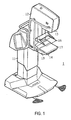
- the mammography apparatus 1 presented in figure 1 consists of a body part 11 and a C-arm 12 connected to it.
- a radiation source 13 and, e.g. inside the lower shelf 14, image data receiving means 15 are placed on the opposite ends of the C-arm 12, which imaging means 13, 15 when being situated inside the cover of the apparatus are not actually visible in figure 1.
- means 16, 17 for positioning the object to be imaged within the imaging area are located within the area between these imaging means 13, 15, typically near the image data receiving means 15.
- the C-arm 12 is movable both in vertical direction in relation to means 16, 17 for positioning the object to be imaged and rotatable in relation to the body part 11.
- the positioning means 16, 17 are typically formed of an upper compression paddle 16 and a lower compression paddle 17, which lower compression paddle 17 may be arranged to function as a so called bucky as well.
- Bucky means a grid structure located between the tissue to be imaged and the image data receiving means, which grid structure restricts access of the radiation scattered from the tissue to the image data receiving means.
- figure 2 which is not drawn in scale, is presented in a simplified manner one way to implement a sensor arrangement 15 of a mammography apparatus according to the invention.
- a radiation source 13 and its focus 42 the radiation source being situated at the first end of the C-arm 12.
- a collimator apparatus including a collimator 19, which is arranged to be moved in synch with at least one sensor 50 belonging to the sensor arrangement 15 of the imaging apparatus.
- the collimator apparatus consists of an actuator 20, such as a motor, which may be operated programmatically and makes a bearing-mounted 22 screw 21 rotate.
- the collimator 19 there are ledges, 23 or equivalent, which include such an inner thread fitted to the screw 21 that when the screw 21 is rotated, the collimator 19 moves in direction of the middle axis of the screw 21.
- the arrow 33 presents the direction of the scanning movement of the beam defined by the collimator 19.
- the radiolucent upper and lower compression paddles 16, 17 function as positioning means of the object to be imaged, which compression paddles are located between the radiation source 13 and the lower shelf 14, which is situated at the other end of the C-arm in such a way that the lower shelf 14 is situated near the lower surface of the lower compression paddle 17.
- the lower shelf 14 as such can be arranged to function also as the lower compression paddle 17.
- the surfaces of the compression paddles 16, 17, which become against the object to be imaged, are essentially plane-like.
- the sensor arrangement 15, which is situated in the essential vicinity of the lower compression paddle 17 inside the lower shelf 14, is implemented according to figure 2 by connecting the image data receiving sensor 50 to a transmission element 28, which is equipped with an inner thread and through which extends a rotatable bearing-mounted 26 screw 25, said screw being preferably programmatically operable by an actuator 24, such as a motor.
- an actuator 24 such as a motor.
- the sensor 50 moves in a linear fashion in the direction of the middle axis of the screw 25.
- a bearing-mounted or an articulated connection has been arranged between the transmission element 28 and the sensor 50 to enable their mutual rotational movement.
- a longitudinal control arm 30 is attached motionless to the sensor 50, which control arm is essentially straight and extends away from the sensor 50 in direction of the beam.
- control element 29 in the control arm 30 there is a longitudinal trajectory groove 31 extending essentially in the direction of the beam, in which groove there is fitted a control element 29, respectively, which can thus move in the direction of the longitudinal axis of the control arm 30.
- the control element 29 according to figure 2 consists of a body, which has three projections extending outwards from the centre of the body, the projections being at 120° angles to each other and having rollers 32 at their ends.
- the rollers 32 are pivoted to be rotatable around their middle axles.
- Within the lower shelf 14 there is further arranged a longitudinal curved guide groove 34, the radius of curvature of which corresponds the distance of the groove 34 from the focus 42 of the radiation source 13.
- the control element 29 is arranged movable in the guide groove 34.
- the solution according to figure 2 functions such that when the sensor 50 is moved essentially linearly along the screw 21 by control of the actuator 24, whereby it concurrently moves the control element 29 along the curved guide groove 34, position of the sensor 50 in relation to the direction of the linear movement determined by the screw 21 continuously tilts in such a way that the active surface of the sensor 50 remains essentially at right angles to the beam on the plane formed by the scanning movement of the beam, because of being guided by the shape of the guide groove 34 as well as the structures arranged for the control arm 31 and the transmission element 28.
- control arrangement of the imaging apparatus 1 controls the actuators 20, 24 which rotate the screws 21 and 25 in such a way that during the imaging scan the beam originating from the radiation source 13 and being defined by the collimator 19 moves in synch with the active surface of the sensor 50, i.e. in a way that the collimator 19 and the sensor 50 move in the same direction with speeds synchronized with each other.
- the linear movement of the collimator 19 and the sensor 50 can be arranged synchronized also by connecting them together mechanically.
- means may be arranged to the collimator 19 for adjusting the width of the beam during the imaging scan.
- figure 3 which is not drawn in scale either, is presented in a simplified manner another way of implementing the sensor arrangement 15 of the mammography apparatus 1 according to the invention.
- a pendulum arm 35 is arranged to the imaging apparatus, the focus of rotation of which being arranged on the level of the focus 42 of the radiation source 13.
- Moving of the collimator 19 (not shown in figure 3), which is arranged in close proximity to the radiation source 13, may be implemented not only as according to figure 2 but also by arranging it in mechanical connection with the pendulum arm 35 in such a way that the collimator 19 follows the movements of the pendulum arm 35.
- Such a structure additionally includes an actuator (not shown in the figure) for producing the movement 41 of the pendulum arm 35 with respect to the focus of rotation 42.
- the sensor 50 receiving image information is attached motionless to the lower part of the pendulum arm 35 with the exception that it is allowed to move in the direction of the longitudinal axis of the pendulum arm 35, e.g. along a guide groove 39 arranged to the pendulum arm 35.
- a transmission element 40 is connected to the sensor 50, which element is connected by a bearing-mounted or an articulated connection to a control element 37 equipped with wheels 38 to enable mutual rotational movement between the sensor 50 and the control element 37.
- the solution according to figure 3 can be modified e.g. such that the sensor 50 is attached to the pendulum arm 35 completely motionless and the pendulum arm 35 will be provided with means, such as a telescope structure, for altering its length in such a way that the movement of the sensor 50 in the scanning direction becomes linear.
- means such as a telescope structure
- moving of the sensor can be implemented by other means than those presented above, too, e.g. by arranging a separate actuator to tilt the sensor or by moving the sensor and/or a guide element attached motionlessly to it in a guide groove or a tunnel, which is designed such that also the sensor movement according to the invention will be accomplished by a mechanically forced control.
- the possible linear movement of the collimator may be implemented by a corresponding manner self-evident to a person skilled in the art as the linear movement of the sensor.
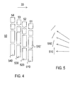
- the sensor 50 can consist of e.g. four in the scanning direction consecutive sensor module columns 51, 52, 53, 54, in which columns separate sensor modules 510, 510', ... are placed at right angles to the scanning movement 33 in slightly different positions such that the possible seams of the sensor surfaces of the modules 510, 510', ... will become placed at slightly various heights in each column. This secures that the possible gaps between the modules 510, 510', ... will be imaged anyhow via the three other module columns and no gaps will be left in the image formed.
- the overlap may be implemented by e.g.
- dpix x (n+1/m) diameter of the pixel
- n integer
- m number of the modules in the observation direction or an integer smaller than that, whereby the imaging resolution of the sensor module may be increased to be higher than that of the physical pixel size with the help of signal processing functions.
- the corresponding overlaps and distances between the modules 510, 510', ... may also be implemented between those sensor modules consecutive in the scanning direction, whereupon also the resolution in the direction of the scanning movement may be increased correspondingly.
- separate sensor modules 510, 510', ... may be clocked in a way self-evident to a person skilled in the art to achieve a corresponding effect that increases resolution also in the direction of the scanning movement.
- a single module 510, 510', ... may be formed of e.g. 142 x 284 pixels of 35 mm and may form a sensor surface of an area of 5 mm x 10 mm, when the sensor arrangement as a whole may contain e.g. in the width direction four and in the height direction about 20 such modules, thereby forming a sensor 50 of ca. 20 mm by width and e.g. ca. 240 mm by heidth.
- the distance between the modules 510, 510', ... is not critical.
- a shift register may be arranged on the other of the vertical edges of each sensor module 510, 510', ... without the space occupied by it essentially troubling the imaging.
- each of the modules may be placed essentially at right angles to the focus 42 of the beam used in the imaging also in the direction perpendicular to the scanning direction.
Landscapes
- Health & Medical Sciences (AREA)
- Life Sciences & Earth Sciences (AREA)
- Medical Informatics (AREA)
- Engineering & Computer Science (AREA)
- Optics & Photonics (AREA)
- Biomedical Technology (AREA)
- Biophysics (AREA)
- High Energy & Nuclear Physics (AREA)
- Oral & Maxillofacial Surgery (AREA)
- Nuclear Medicine, Radiotherapy & Molecular Imaging (AREA)
- Dentistry (AREA)
- Pathology (AREA)
- Radiology & Medical Imaging (AREA)
- Physics & Mathematics (AREA)
- Heart & Thoracic Surgery (AREA)
- Molecular Biology (AREA)
- Surgery (AREA)
- Animal Behavior & Ethology (AREA)
- General Health & Medical Sciences (AREA)
- Public Health (AREA)
- Veterinary Medicine (AREA)
- Apparatus For Radiation Diagnosis (AREA)
- Analysing Materials By The Use Of Radiation (AREA)
Applications Claiming Priority (3)
| Application Number | Priority Date | Filing Date | Title |
|---|---|---|---|
| FI20022148A FI117542B (fi) | 2002-12-04 | 2002-12-04 | Digitaalinen mammografiakuvantamismenetelmä ja -laite |
| FI20022148 | 2002-12-04 | ||
| PCT/FI2003/000930 WO2004049946A1 (en) | 2002-12-04 | 2003-12-04 | Digital imaging method and apparatus for mammography |
Publications (2)
| Publication Number | Publication Date |
|---|---|
| EP1578273A1 EP1578273A1 (en) | 2005-09-28 |
| EP1578273B1 true EP1578273B1 (en) | 2007-08-29 |
Family
ID=8565038
Family Applications (1)
| Application Number | Title | Priority Date | Filing Date |
|---|---|---|---|
| EP03812200A Expired - Lifetime EP1578273B1 (en) | 2002-12-04 | 2003-12-04 | Digital imaging method and apparatus for mammography |
Country Status (8)
Families Citing this family (15)
| Publication number | Priority date | Publication date | Assignee | Title |
|---|---|---|---|---|
| US7497625B2 (en) | 2004-06-08 | 2009-03-03 | General Electric Company | Systems, methods and apparatus of an extending column |
| FR2875693B1 (fr) | 2004-09-24 | 2006-12-08 | Gen Electric | Dispositif de tomographie par rayons x |
| FR2878425B1 (fr) * | 2004-11-26 | 2007-03-16 | Gen Electric | Equipements de radiographie mammaire |
| JP4837507B2 (ja) * | 2005-10-06 | 2011-12-14 | 富士フイルム株式会社 | 乳房画像撮影装置 |
| US7607183B2 (en) | 2005-11-15 | 2009-10-27 | General Electric Company | Braking system for a positioner in a medical imaging apparatus |
| US7954996B2 (en) * | 2008-07-08 | 2011-06-07 | General Electric Company | Positioning system with tilting arm support for imaging devices |
| WO2011153555A2 (en) * | 2010-06-03 | 2011-12-08 | Caperay Medical (Pty) Ltd | Dual-modality scanning system for detecting breast cancer |
| KR20140043317A (ko) * | 2011-02-01 | 2014-04-09 | 덱셀라 리미티드 | 제한된 다이나믹 레인지의 전역 디지털 유방촬영(ffdm)을 이용한 큰 다이나믹 레인지의 유방조영술 |
| JP6053772B2 (ja) * | 2011-07-04 | 2016-12-27 | コーニンクレッカ フィリップス エヌ ヴェKoninklijke Philips N.V. | X線イメージング装置のスキャン運動を適合させる |
| KR101473531B1 (ko) | 2012-11-13 | 2014-12-17 | 인제대학교 산학협력단 | 적응형 센서유닛, 그를 이용한 x-선 촬영 장치 및 방법 |
| CN105682553A (zh) * | 2013-10-22 | 2016-06-15 | 皇家飞利浦有限公司 | 用于采集对象的图像的x射线系统特别是断层摄影组合系统和方法 |
| FI20155005A7 (fi) * | 2015-01-02 | 2016-07-03 | Palodex Group Oy | Röntgenkuvantamisyksikkö lääketieteelliseen kuvantamiseen |
| US10813608B2 (en) * | 2018-10-02 | 2020-10-27 | General Electric Company | Method and systems for a mobile imaging system |
| CN111265784B (zh) * | 2018-11-20 | 2025-03-25 | 西安大医集团股份有限公司 | 一种光阑位置检测装置及医用加速器治疗头 |
| WO2020142977A1 (en) * | 2019-01-10 | 2020-07-16 | Shenzhen Xpectvision Technology Co., Ltd. | Image sensor having radiation detectors of different orientations |
Family Cites Families (15)
| Publication number | Priority date | Publication date | Assignee | Title |
|---|---|---|---|---|
| US4203037A (en) * | 1977-08-01 | 1980-05-13 | University Of Pittsburgh | Collimated radiation apparatus |
| DE2951857A1 (de) * | 1979-12-21 | 1981-07-02 | Siemens AG, 1000 Berlin und 8000 München | Roentgendiagnostikanlage mit einer aufnahmeeinheit mit einer roentgenroehre, die ein faecherfoermiges strahlenbuendel aussenden kann |
| US4628356A (en) * | 1984-10-15 | 1986-12-09 | Imagex, Inc. | Digital X-ray scanner |
| JPH07114768B2 (ja) * | 1987-04-22 | 1995-12-13 | 松下電器産業株式会社 | X線診断装置 |
| CA2014918A1 (en) * | 1989-09-06 | 1991-03-06 | James A. Mcfaul | Scanning mammography system with improved skin line viewing |
| US5526394A (en) | 1993-11-26 | 1996-06-11 | Fischer Imaging Corporation | Digital scan mammography apparatus |
| US5483072A (en) * | 1994-08-04 | 1996-01-09 | Bennett X-Ray Technologies | Automatic position control system for x-ray machines |
| US5712890A (en) * | 1994-11-23 | 1998-01-27 | Thermotrex Corp. | Full breast digital mammography device |
| FI99074C (fi) * | 1995-11-21 | 1997-09-25 | Planmed Oy | Menetelmä ja laite digitaaliseen kuvantamiseen tarkoitetun kameran anturijärjestelmän muodostamiseksi |
| US6164820A (en) * | 1998-05-06 | 2000-12-26 | Siemens Aktiengesellschaft | X-ray examination system particulary for computed tomography and mammography |
| US6292531B1 (en) * | 1998-12-31 | 2001-09-18 | General Electric Company | Methods and apparatus for generating depth information mammography images |
| EP1062913A1 (en) * | 1999-06-25 | 2000-12-27 | DDI Direct Digital Imaging GmbH | Digital scanning and photographic imaging X-ray system |
| SE524380C2 (sv) * | 2002-03-12 | 2004-08-03 | Xcounter Ab | Exponeringsstyrning i scannerbaserad detektering av joniserande strålning |
| US20030194050A1 (en) * | 2002-04-15 | 2003-10-16 | General Electric Company | Multi modality X-ray and nuclear medicine mammography imaging system and method |
| JP2004208773A (ja) * | 2002-12-27 | 2004-07-29 | Konica Minolta Holdings Inc | 放射線画像形成システム |
-
2002
- 2002-12-04 FI FI20022148A patent/FI117542B/fi not_active IP Right Cessation
-
2003
- 2003-12-04 WO PCT/FI2003/000930 patent/WO2004049946A1/en active IP Right Grant
- 2003-12-04 AU AU2003302575A patent/AU2003302575A1/en not_active Abandoned
- 2003-12-04 AT AT03812200T patent/ATE371406T1/de not_active IP Right Cessation
- 2003-12-04 DE DE60316027T patent/DE60316027T2/de not_active Expired - Lifetime
- 2003-12-04 US US10/537,334 patent/US7590217B2/en not_active Expired - Fee Related
- 2003-12-04 EP EP03812200A patent/EP1578273B1/en not_active Expired - Lifetime
- 2003-12-04 JP JP2004556384A patent/JP2006508722A/ja active Pending
Also Published As
| Publication number | Publication date |
|---|---|
| DE60316027D1 (de) | 2007-10-11 |
| FI20022148A0 (fi) | 2002-12-04 |
| JP2006508722A (ja) | 2006-03-16 |
| US7590217B2 (en) | 2009-09-15 |
| US20060050843A1 (en) | 2006-03-09 |
| WO2004049946A1 (en) | 2004-06-17 |
| AU2003302575A1 (en) | 2004-06-23 |
| ATE371406T1 (de) | 2007-09-15 |
| FI20022148A7 (fi) | 2004-06-05 |
| EP1578273A1 (en) | 2005-09-28 |
| DE60316027T2 (de) | 2008-05-21 |
| FI117542B (fi) | 2006-11-30 |
Similar Documents
| Publication | Publication Date | Title |
|---|---|---|
| EP1578273B1 (en) | Digital imaging method and apparatus for mammography | |
| US8842806B2 (en) | Apparatus and method for breast imaging | |
| EP1485024B1 (en) | X-ray apparatus provided with a positionally adjustable x-ray detector | |
| EP0333256B1 (en) | X-ray examination apparatus having three axes of rotation | |
| KR101499267B1 (ko) | 치과 및 안면 촬상 장치 | |
| US8503603B2 (en) | Adjustable scanner | |
| US7300205B2 (en) | Angio capable portable x-ray fluoroscopy unit with sliding C-arm and variable pivot | |
| JP2855195B2 (ja) | 4本の回転軸線を有するアイソセンタ式x線撮影装置用スタンド | |
| US20200182807A1 (en) | System and method for cabinet x-ray systems with stationary x-ray source array | |
| EP2502561B1 (en) | Arc-shaped medical imaging equipment | |
| US20170347978A1 (en) | Urology table with tiltable x-ray tube | |
| US8256957B1 (en) | Bi-directional mobile radiographic image receptor assembly and use thereof | |
| US10265033B2 (en) | CT photographic device comprising a rotary driving part and a linear driving part | |
| US11890123B2 (en) | Multimodal system for breast imaging | |
| JPH1099311A (ja) | レントゲン診断機器 | |
| US20050169432A1 (en) | X-ray device | |
| US6302580B1 (en) | Apparatus for solid state digital imager tracking radiography | |
| US6452997B1 (en) | Method for use in tomographic imaging | |
| US6075837A (en) | Image minifying radiographic and fluoroscopic x-ray system | |
| CN110403618A (zh) | 乳房x射线摄影装置 | |
| JP2020156620A (ja) | X線撮影装置 | |
| WO1996006561A1 (en) | Self-contained apparatus for skeletal radiographic tomography | |
| JP2000504261A (ja) | トモグラフィー画像の形成に適した医療用x線装置 | |
| US20220273251A1 (en) | X-ray imaging apparatus | |
| JP2816730B2 (ja) | 空間内で移動可能な等角点を持つ放射線医学装置 |
Legal Events
| Date | Code | Title | Description |
|---|---|---|---|
| PUAI | Public reference made under article 153(3) epc to a published international application that has entered the european phase |
Free format text: ORIGINAL CODE: 0009012 |
|
| 17P | Request for examination filed |
Effective date: 20050704 |
|
| AK | Designated contracting states |
Kind code of ref document: A1 Designated state(s): AT BE BG CH CY CZ DE DK EE ES FI FR GB GR HU IE IT LI LU MC NL PT RO SE SI SK TR |
|
| AX | Request for extension of the european patent |
Extension state: AL LT LV MK |
|
| DAX | Request for extension of the european patent (deleted) | ||
| GRAP | Despatch of communication of intention to grant a patent |
Free format text: ORIGINAL CODE: EPIDOSNIGR1 |
|
| GRAS | Grant fee paid |
Free format text: ORIGINAL CODE: EPIDOSNIGR3 |
|
| GRAA | (expected) grant |
Free format text: ORIGINAL CODE: 0009210 |
|
| AK | Designated contracting states |
Kind code of ref document: B1 Designated state(s): AT BE BG CH CY CZ DE DK EE ES FI FR GB GR HU IE IT LI LU MC NL PT RO SE SI SK TR |
|
| REG | Reference to a national code |
Ref country code: GB Ref legal event code: FG4D |
|
| REG | Reference to a national code |
Ref country code: CH Ref legal event code: EP |
|
| REG | Reference to a national code |
Ref country code: IE Ref legal event code: FG4D |
|
| REF | Corresponds to: |
Ref document number: 60316027 Country of ref document: DE Date of ref document: 20071011 Kind code of ref document: P |
|
| REG | Reference to a national code |
Ref country code: SE Ref legal event code: TRGR |
|
| PG25 | Lapsed in a contracting state [announced via postgrant information from national office to epo] |
Ref country code: FI Free format text: LAPSE BECAUSE OF FAILURE TO SUBMIT A TRANSLATION OF THE DESCRIPTION OR TO PAY THE FEE WITHIN THE PRESCRIBED TIME-LIMIT Effective date: 20070829 Ref country code: NL Free format text: LAPSE BECAUSE OF FAILURE TO SUBMIT A TRANSLATION OF THE DESCRIPTION OR TO PAY THE FEE WITHIN THE PRESCRIBED TIME-LIMIT Effective date: 20070829 Ref country code: ES Free format text: LAPSE BECAUSE OF FAILURE TO SUBMIT A TRANSLATION OF THE DESCRIPTION OR TO PAY THE FEE WITHIN THE PRESCRIBED TIME-LIMIT Effective date: 20071210 |
|
| NLV1 | Nl: lapsed or annulled due to failure to fulfill the requirements of art. 29p and 29m of the patents act | ||
| PG25 | Lapsed in a contracting state [announced via postgrant information from national office to epo] |
Ref country code: CH Free format text: LAPSE BECAUSE OF FAILURE TO SUBMIT A TRANSLATION OF THE DESCRIPTION OR TO PAY THE FEE WITHIN THE PRESCRIBED TIME-LIMIT Effective date: 20070829 Ref country code: LI Free format text: LAPSE BECAUSE OF FAILURE TO SUBMIT A TRANSLATION OF THE DESCRIPTION OR TO PAY THE FEE WITHIN THE PRESCRIBED TIME-LIMIT Effective date: 20070829 Ref country code: AT Free format text: LAPSE BECAUSE OF FAILURE TO SUBMIT A TRANSLATION OF THE DESCRIPTION OR TO PAY THE FEE WITHIN THE PRESCRIBED TIME-LIMIT Effective date: 20070829 |
|
| REG | Reference to a national code |
Ref country code: CH Ref legal event code: PL |
|
| PG25 | Lapsed in a contracting state [announced via postgrant information from national office to epo] |
Ref country code: BE Free format text: LAPSE BECAUSE OF FAILURE TO SUBMIT A TRANSLATION OF THE DESCRIPTION OR TO PAY THE FEE WITHIN THE PRESCRIBED TIME-LIMIT Effective date: 20070829 |
|
| EN | Fr: translation not filed | ||
| PG25 | Lapsed in a contracting state [announced via postgrant information from national office to epo] |
Ref country code: GR Free format text: LAPSE BECAUSE OF FAILURE TO SUBMIT A TRANSLATION OF THE DESCRIPTION OR TO PAY THE FEE WITHIN THE PRESCRIBED TIME-LIMIT Effective date: 20071130 Ref country code: DK Free format text: LAPSE BECAUSE OF FAILURE TO SUBMIT A TRANSLATION OF THE DESCRIPTION OR TO PAY THE FEE WITHIN THE PRESCRIBED TIME-LIMIT Effective date: 20070829 |
|
| ET | Fr: translation filed | ||
| REG | Reference to a national code |
Ref country code: FR Ref legal event code: EERR Free format text: CORRECTION DE BOPI 08/17 - BREVETS EUROPEENS DONT LA TRADUCTION N A PAS ETE REMISE A L INPI. IL Y A LIEU DE SUPPRIMER : LA MENTION DE LA NON-REMISE. LA REMISE DE LA TRADUCTION EST PUBLIEE DANS LE PRESENT BOPI. |
|
| PG25 | Lapsed in a contracting state [announced via postgrant information from national office to epo] |
Ref country code: SK Free format text: LAPSE BECAUSE OF FAILURE TO SUBMIT A TRANSLATION OF THE DESCRIPTION OR TO PAY THE FEE WITHIN THE PRESCRIBED TIME-LIMIT Effective date: 20070829 Ref country code: PT Free format text: LAPSE BECAUSE OF FAILURE TO SUBMIT A TRANSLATION OF THE DESCRIPTION OR TO PAY THE FEE WITHIN THE PRESCRIBED TIME-LIMIT Effective date: 20080129 Ref country code: CZ Free format text: LAPSE BECAUSE OF FAILURE TO SUBMIT A TRANSLATION OF THE DESCRIPTION OR TO PAY THE FEE WITHIN THE PRESCRIBED TIME-LIMIT Effective date: 20070829 |
|
| PG25 | Lapsed in a contracting state [announced via postgrant information from national office to epo] |
Ref country code: RO Free format text: LAPSE BECAUSE OF FAILURE TO SUBMIT A TRANSLATION OF THE DESCRIPTION OR TO PAY THE FEE WITHIN THE PRESCRIBED TIME-LIMIT Effective date: 20070829 |
|
| PLBE | No opposition filed within time limit |
Free format text: ORIGINAL CODE: 0009261 |
|
| STAA | Information on the status of an ep patent application or granted ep patent |
Free format text: STATUS: NO OPPOSITION FILED WITHIN TIME LIMIT |
|
| PG25 | Lapsed in a contracting state [announced via postgrant information from national office to epo] |
Ref country code: MC Free format text: LAPSE BECAUSE OF NON-PAYMENT OF DUE FEES Effective date: 20071231 |
|
| 26N | No opposition filed |
Effective date: 20080530 |
|
| GBPC | Gb: european patent ceased through non-payment of renewal fee |
Effective date: 20071204 |
|
| PG25 | Lapsed in a contracting state [announced via postgrant information from national office to epo] |
Ref country code: IE Free format text: LAPSE BECAUSE OF NON-PAYMENT OF DUE FEES Effective date: 20071204 |
|
| PG25 | Lapsed in a contracting state [announced via postgrant information from national office to epo] |
Ref country code: GB Free format text: LAPSE BECAUSE OF NON-PAYMENT OF DUE FEES Effective date: 20071204 |
|
| PG25 | Lapsed in a contracting state [announced via postgrant information from national office to epo] |
Ref country code: EE Free format text: LAPSE BECAUSE OF FAILURE TO SUBMIT A TRANSLATION OF THE DESCRIPTION OR TO PAY THE FEE WITHIN THE PRESCRIBED TIME-LIMIT Effective date: 20070829 |
|
| PG25 | Lapsed in a contracting state [announced via postgrant information from national office to epo] |
Ref country code: SI Free format text: LAPSE BECAUSE OF FAILURE TO SUBMIT A TRANSLATION OF THE DESCRIPTION OR TO PAY THE FEE WITHIN THE PRESCRIBED TIME-LIMIT Effective date: 20070829 |
|
| PG25 | Lapsed in a contracting state [announced via postgrant information from national office to epo] |
Ref country code: CY Free format text: LAPSE BECAUSE OF FAILURE TO SUBMIT A TRANSLATION OF THE DESCRIPTION OR TO PAY THE FEE WITHIN THE PRESCRIBED TIME-LIMIT Effective date: 20070829 |
|
| PG25 | Lapsed in a contracting state [announced via postgrant information from national office to epo] |
Ref country code: BG Free format text: LAPSE BECAUSE OF FAILURE TO SUBMIT A TRANSLATION OF THE DESCRIPTION OR TO PAY THE FEE WITHIN THE PRESCRIBED TIME-LIMIT Effective date: 20071129 Ref country code: LU Free format text: LAPSE BECAUSE OF NON-PAYMENT OF DUE FEES Effective date: 20071204 |
|
| PG25 | Lapsed in a contracting state [announced via postgrant information from national office to epo] |
Ref country code: TR Free format text: LAPSE BECAUSE OF FAILURE TO SUBMIT A TRANSLATION OF THE DESCRIPTION OR TO PAY THE FEE WITHIN THE PRESCRIBED TIME-LIMIT Effective date: 20070829 Ref country code: HU Free format text: LAPSE BECAUSE OF FAILURE TO SUBMIT A TRANSLATION OF THE DESCRIPTION OR TO PAY THE FEE WITHIN THE PRESCRIBED TIME-LIMIT Effective date: 20080301 |
|
| PGFP | Annual fee paid to national office [announced via postgrant information from national office to epo] |
Ref country code: IT Payment date: 20131122 Year of fee payment: 11 |
|
| PGFP | Annual fee paid to national office [announced via postgrant information from national office to epo] |
Ref country code: FR Payment date: 20131219 Year of fee payment: 11 |
|
| REG | Reference to a national code |
Ref country code: FR Ref legal event code: ST Effective date: 20150831 |
|
| PG25 | Lapsed in a contracting state [announced via postgrant information from national office to epo] |
Ref country code: FR Free format text: LAPSE BECAUSE OF NON-PAYMENT OF DUE FEES Effective date: 20141231 |
|
| PG25 | Lapsed in a contracting state [announced via postgrant information from national office to epo] |
Ref country code: IT Free format text: LAPSE BECAUSE OF NON-PAYMENT OF DUE FEES Effective date: 20141204 |
|
| PGFP | Annual fee paid to national office [announced via postgrant information from national office to epo] |
Ref country code: SE Payment date: 20171123 Year of fee payment: 15 |
|
| REG | Reference to a national code |
Ref country code: SE Ref legal event code: EUG |
|
| PG25 | Lapsed in a contracting state [announced via postgrant information from national office to epo] |
Ref country code: SE Free format text: LAPSE BECAUSE OF NON-PAYMENT OF DUE FEES Effective date: 20181205 |
|
| PGFP | Annual fee paid to national office [announced via postgrant information from national office to epo] |
Ref country code: DE Payment date: 20191119 Year of fee payment: 17 |
|
| REG | Reference to a national code |
Ref country code: DE Ref legal event code: R119 Ref document number: 60316027 Country of ref document: DE |
|
| PG25 | Lapsed in a contracting state [announced via postgrant information from national office to epo] |
Ref country code: DE Free format text: LAPSE BECAUSE OF NON-PAYMENT OF DUE FEES Effective date: 20210701 |