EP1578180A1 - Netzgerät - Google Patents
Netzgerät Download PDFInfo
- Publication number
- EP1578180A1 EP1578180A1 EP04006522A EP04006522A EP1578180A1 EP 1578180 A1 EP1578180 A1 EP 1578180A1 EP 04006522 A EP04006522 A EP 04006522A EP 04006522 A EP04006522 A EP 04006522A EP 1578180 A1 EP1578180 A1 EP 1578180A1
- Authority
- EP
- European Patent Office
- Prior art keywords
- power supply
- supply unit
- spacer
- unit according
- spacers
- Prior art date
- Legal status (The legal status is an assumption and is not a legal conclusion. Google has not performed a legal analysis and makes no representation as to the accuracy of the status listed.)
- Granted
Links
Images


Classifications
-
- H—ELECTRICITY
- H05—ELECTRIC TECHNIQUES NOT OTHERWISE PROVIDED FOR
- H05K—PRINTED CIRCUITS; CASINGS OR CONSTRUCTIONAL DETAILS OF ELECTRIC APPARATUS; MANUFACTURE OF ASSEMBLAGES OF ELECTRICAL COMPONENTS
- H05K5/00—Casings, cabinets or drawers for electric apparatus
- H05K5/30—Side-by-side or stacked arrangements
Definitions
- the invention relates to a built-in power supply for installation in a Control cabinet or the like with the features of the Preamble of claim 1.
- installation power supplies used, the input voltage as needed in one or several different output voltages for supply transform electrical consumers.
- Such installation power supplies are used in control cabinets or similar assembly facilities installed, for example, snap connections for mounting on a mounting rail of the control cabinet can be provided.
- the mounting rails are standardized, so that a built-in power supply in series with comparable power supplies or other electrical equipment like circuit breaker or the like next to each other can be arranged on the rail.
- the invention is based on the object, a built-in power supply develop the genus described in the introduction such that a better cooling effect is ensured.
- a built-in power supply in the area in at least one of its two side walls at least one spacer is arranged. Through the spacer is ensured that the associated side wall in the mounted position of the power supply unit a minimum distance to a neighboring device or another arranged laterally Component has. Due to the minimum distance is on the Outside of the associated side wall given a free space, discharged via the released heat to an air flow can be.
- the heating of the side wall creates a Convection current, both outside and inside bypasses the sidewall and provides cooling on both sides, so that sufficient heat energy can be delivered. Overheating can even in fully populated Cabinets are reliably avoided.
- the invention is described as a built-in power supply; including housing can also be understood, the other dissipation generating Have internals and also to cool accordingly. Such installations may be relays, valves or electronic Be performance groups.
- both side walls at least one spacer each provided.
- the two Spacers can be in their laterally directed Height should be such that the given minimum free space adapted to the expected power loss of the power supply is.
- the spacer with respect to a through the intended installation position predetermined high direction a Longitudinal extension, in particular at least about one Third of a height of the associated side wall amounts.
- a Longitudinal extension in particular at least about one Third of a height of the associated side wall amounts.
- the spacer is based on the high direction at least approximately in the middle of the associated Sidewall arranged. Lateral contact forces on Spacers are at least approximately centric in the housing initiated. A tilting or tilting in the Assembly is avoided. Two are useful in the field of two opposing side walls arranged spacers at least approximately in relation to the vertical direction same height arranged. In particular in connection with a results in this area centrally extending mounting rail there is a central force introduction into the spacers, which at least about centric forces on the mounting rail counteract. A tilt-free installation is facilitated.
- two are opposite one another Side walls arranged spacers relative to the Vertical direction so offset from each other, that the facing spacers in mounting position lie one above the other.
- the perpendicular to the side wall extending height of the spacers can be chosen so be that the height of the required for cooling double Gap width corresponds.
- the power supply unit has a Mounting wall on, with the spacer in a corner area arranged between the associated side wall and the mounting wall is.
- the associated mounting rail acts the spacer and leads the power supply, for example, between two preassembled Devices at the intended distance through.
- a subsequent one Engaging the mounting rail is centered Position.
- a subsequent correction of the lateral Location is not required.
- the spacer refers in the mounting direction of the power supply a front mounting slope on.
- a later to be installed neighboring device with or without its own spacer needs only roughly prepositioned be and slides when inserted on the mounting slope in the intended lateral distance position.
- the spacer expediently has a groove in particular three angles to each other, the mounting rail at least partially enclosing contact surfaces. It results itself a formmatie determination of the power supply to the Mounting rail with a tilt-free support in several Spatial directions.
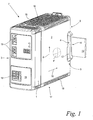
- Fig. 1 shows in a perspective overview representation a built-in power supply 7, on an indicated mounting rail 13 in a control cabinet, not shown, or the like is attached.
- the built-in power supply 7 has a housing 1 with opposite side walls 2, 3, with a upper and a lower wall 16, 17, with a front wall 15 and with a rear mounting wall 8.
- the housing 1 Can be designed as a sheet metal housing, but also as a plastic housing be. Both housings have advantages.
- the lower wall 17 and the upper wall 16 are respectively formed in the form of a grid 18, resulting in the Inside of the power supply unit 7 in the direction indicated by an arrow 6 and by the mounting position shown predetermined vertical direction a convection current in the interior of the housing 1 to Can form cooling.
- the spacer 4 in a corner region 9, in which the Side wall 2 adjacent to the rear mounting wall 8, a laterally over the contour of the power supply 7 protruding spacers 4 arranged.
- the spacer 4 also be formed as a survey on the side surface 2, as shown in Fig. 1 by dashed lines.
- the shape of the spacer 4, 4 " can be rib-shaped, partially spherical, elliptical or the like.
- the rib-shaped spacer 4 shown has a groove 14, the mounting rail 13 approximately positively engages around.
- an arrow 10 is a Mounting direction indicated, in which the power supply unit 7 is mounted and is placed on the mounting rail 13.
- the spacer 4 has a front side relative to the mounting direction 10 Mounting slope 12 on.
- Spacer 5 is provided.
- the spacers 4, 5 are in shown embodiment in one piece with the respectively associated Side wall 2, 3 formed in the embodiment in Form of an elongated hollow rib made of plastic; it may be appropriate be, instead of the hollow rib a rib of solid material provided.
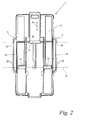
- Fig. 2 shows a rear view of the power supply unit 7 of FIG. 1 with the two mirror-symmetrically opposing spacers 4, 5.
- the groove 14 in the spacers 4, 5 is with three mutually perpendicular contact surfaces 20 provided that the mounting rail 13 surface and backlash encircling on three sides.
- Another, opposite hook 23rd is provided on a resilient tab 22 and engages behind also the mounting rail 13.
- the tab 22 is in the direction a double arrow 24 displaceable against a spring force, whereby the power supply unit 7 with respect to the mounting rail 13th can be unlocked or locked.
- Fig. 3 shows a front view of an arrangement of two Power supply units 7, 7 'according to FIGS. 1 and 2.
- the two power supplies 7, 7 ' are immediately adjacent to each other on the side Mounting rail 13 is fixed, wherein the spacer 4 of the Power supply unit 7 laterally and flat on the adjacent spacer 5 'of the adjacent power supply 7' is applied.
- the Spacers 4, 4 ', 5, 5' have a height h which is so dimensioned is that the resulting outer air gap for removal the heat of the corresponding power supply unit 7, 7 'is sufficient.
- at the arrangement shown is thus the distance between the two adjoining side walls 2, 3 'twice the height h, whereby the adjacent in the area of both Side walls 2, 3 'released heat to be dissipated can.
- the spacers 4, 4 ', 5, 5' are related to the vertical direction 6 at least approximately centrally on the associated side wall 2, 2 ', 3, 3' are arranged and are in the same amount as the center extending mounting rail 13.
- the spacers 4, 4 ', 5, 5 ' have with respect to the vertical direction 6 a longitudinal extension a, which in the embodiment shown approximately one third of a height H of the associated side wall 2, 2 ', 3, 3 'is.
- Each in the area of the two opposite side walls 2, 3 or the two opposite side walls 2 ', 3' arranged spacers 4, 5, 4 ', 5' are relative to the vertical direction 6 at the same height.
- Fig. 4 shows a variant of the arrangement according to Fig. 3 with two mounted adjacent to each other, similarly constructed Power supply units 7, 7 '.
- spacers 4, 5, 4 ', 5' are relative to the vertical direction 6 against each other offset in height, that the facing spacers 4, 5 'of the two adjacently mounted power supplies _7, 7' not abut each other. Rather, the spacer 4 is the Power supply unit 7 on the side wall 3 'of the power supply unit 7' and the Spacer 5 'on the side wall 2 of the power supply unit 7 at.
- the height h of the spacers 4, 4 ', 5, 5' is chosen so that the resulting Gap between the two power supplies 7, 7 'is so wide that both the heat on the side wall 2 and at the adjacent side wall 3 'through the intermediate gap can be dissipated.
- the embodiment according to FIGS. 1 to 3 match.
- the power supply unit 7 with his Front wall 15 is attached, for example, to a frame. there then forms the front wall 15, the mounting wall 8, in whose Area the spacers 4, 5 can be arranged.
- the spacers can with appropriate design made in one piece with the housing become. If the housings are made of sheet metal, the spacers can be used by imprints or bends from the sidewall be formed.
Landscapes
- Engineering & Computer Science (AREA)
- Microelectronics & Electronic Packaging (AREA)
- Casings For Electric Apparatus (AREA)
- Cooling Or The Like Of Electrical Apparatus (AREA)
Abstract
Description
- Fig. 1
- in einer perspektivischen Übersichtsdarstellung ein Einbaunetzgerät mit seitlichen Abstandshaltern im Bereich einer Montageschiene;
- Fig. 2
- eine Rückansicht des Netzgeräts nach Fig. 1 mit Einzelheiten der Befestigung an der Montageschiene;
- Fig. 3
- in einer Frontansicht zwei benachbart zueinander angeordnete Netzgeräte nach den Fig. 1 und 2;
- Fig. 4
- eine Variante der Anordnung nach Fig. 3 mit gegeneinander höhenversetzt angeordneten Abstandshaltern.
Claims (11)
- Einbaunetzgerät zum Einbau in einen Schaltschrank oder dgl., mit einem Gehäuse (1), welches bezogen auf die vorgesehene Einbauposition zwei Seitenwände (2, 3) aufweist, dadurch gekennzeichnet, daß im Bereich mindestens einer der beiden Seitenwände (2, 3) mindestens ein Abstandshalter (4, 5) angeordnet ist.
- Netzgerät nach Anspruch 1
dadurch gekennzeichnet, daß im Bereich beider Seitenwände (2, 3) je ein Abstandshalter (4, 5) vorgesehen ist. - Netzgerät nach Anspruch 1 oder 2,
dadurch gekennzeichnet, daß der Abstandshalter (4, 5) bezogen auf eine durch die vorgesehene Einbaulage vorgegebene Hochrichtung (6) eine Längserstreckung (a) aufweist, die insbesondere mindestens etwa ein Drittel einer Höhe (H) der zugehörigen Seitenwand (2, 3) beträgt. - Netzgerät nach einem der Ansprüche 1 bis 3,
dadurch gekennzeichnet, daß der Abstandshalter (4, 5) bezogen auf die Hochrichtung (6) zumindest in etwa mittig an der zugehörigen Seitenwand (2, 3) angeordnet ist. - Netzgerät nach einem der Ansprüche 2 bis 4,
dadurch gekennzeichnet, daß zwei im Bereich der beiden sich gegenüberliegenden Seitenwände (2, 3) angeordnete Abstandshalter (4, 5) bezogen auf die Hochrichtung (6) etwa auf gleicher Höhe angeordnet sind. - Netzgerät nach einem der Ansprüche 2 bis 4,
dadurch gekennzeichnet, daß zwei im Bereich der beiden sich gegenüberliegenden Seitenwände (2, 3) angeordnete Abstandshalter (4, 5) bezogen auf die Hochrichtung (6) gegeneinander höhenversetzt sind, derart, daß die einander zugewandten Abstandshalter (4, 5') zweier benachbart montierter Netzgeräte (7, 7') übereinander liegen. - Netzgerät nach einem der Ansprüche 1 bis 6,
dadurch gekennzeichnet, daß das Netzgerät (7) eine Montagewand (8) aufweist, wobei der Abstandshalter (4, 5) in einem Eckbereich (9) zwischen der zugehörigen Seitenwand (4, 5) und der Montagewand (8) angeordnet ist. - Netzgerät nach einem der Ansprüche 1 bis 7,
dadurch gekennzeichnet, daß der Abstandshalter (4, 5) bezogen auf die Montagerichtung (10) des Netzgeräts (7) eine vorderseitige Montageschräge (12) aufweist. - Netzgerät nach einem der Ansprüche 1 bis 8,
dadurch gekennzeichnet, daß der Abstandshalter (4, 5) mit einer Anlagefläche (20) zur Abstützung gegen eine Montageschiene (13) versehen ist. - Netzgerät nach Anspruch 9,
dadurch gekennzeichnet, daß der Abstandshalter (4, 5) eine Nut (14) mit insbesondere drei winklig zueinander liegenden, die Montageschiene (13) zumindest teilweise umschließenden Anlageflächen (20) aufweist. - Netzgerät nach einem der Ansprüche 1 bis 10,
dadurch gekennzeichnet, daß der Abstandshalter (4") als Erhebung in der Seitenwand (2) ausgebildet ist.
Priority Applications (2)
| Application Number | Priority Date | Filing Date | Title |
|---|---|---|---|
| EP04006522A EP1578180B1 (de) | 2004-03-18 | 2004-03-18 | Netzgerät |
| DE502004005127T DE502004005127D1 (de) | 2004-03-18 | 2004-03-18 | Netzgerät |
Applications Claiming Priority (1)
| Application Number | Priority Date | Filing Date | Title |
|---|---|---|---|
| EP04006522A EP1578180B1 (de) | 2004-03-18 | 2004-03-18 | Netzgerät |
Publications (2)
| Publication Number | Publication Date |
|---|---|
| EP1578180A1 true EP1578180A1 (de) | 2005-09-21 |
| EP1578180B1 EP1578180B1 (de) | 2007-10-03 |
Family
ID=34833636
Family Applications (1)
| Application Number | Title | Priority Date | Filing Date |
|---|---|---|---|
| EP04006522A Expired - Lifetime EP1578180B1 (de) | 2004-03-18 | 2004-03-18 | Netzgerät |
Country Status (2)
| Country | Link |
|---|---|
| EP (1) | EP1578180B1 (de) |
| DE (1) | DE502004005127D1 (de) |
Citations (4)
| Publication number | Priority date | Publication date | Assignee | Title |
|---|---|---|---|---|
| DE1815041A1 (de) * | 1968-12-17 | 1970-06-25 | Graesslin Feinwerktech | Schaltungsmodul fuer elektrische Installations-Verteilerschraenke |
| GB1514865A (en) * | 1975-10-14 | 1978-06-21 | Cge Spa | Means for fastening or attaching combinable electric switch units |
| EP0740499A1 (de) * | 1995-04-21 | 1996-10-30 | MAN Roland Druckmaschinen AG | Befestigung einer Baugruppe an einer Hutschiene |
| EP1073323A1 (de) * | 1998-04-01 | 2001-01-31 | Omron Corporation | Elektronische vorrichtung, platteneinrichtung und tragschiene |
-
2004
- 2004-03-18 EP EP04006522A patent/EP1578180B1/de not_active Expired - Lifetime
- 2004-03-18 DE DE502004005127T patent/DE502004005127D1/de not_active Expired - Fee Related
Patent Citations (4)
| Publication number | Priority date | Publication date | Assignee | Title |
|---|---|---|---|---|
| DE1815041A1 (de) * | 1968-12-17 | 1970-06-25 | Graesslin Feinwerktech | Schaltungsmodul fuer elektrische Installations-Verteilerschraenke |
| GB1514865A (en) * | 1975-10-14 | 1978-06-21 | Cge Spa | Means for fastening or attaching combinable electric switch units |
| EP0740499A1 (de) * | 1995-04-21 | 1996-10-30 | MAN Roland Druckmaschinen AG | Befestigung einer Baugruppe an einer Hutschiene |
| EP1073323A1 (de) * | 1998-04-01 | 2001-01-31 | Omron Corporation | Elektronische vorrichtung, platteneinrichtung und tragschiene |
Also Published As
| Publication number | Publication date |
|---|---|
| EP1578180B1 (de) | 2007-10-03 |
| DE502004005127D1 (de) | 2007-11-15 |
Similar Documents
| Publication | Publication Date | Title |
|---|---|---|
| EP0944297B1 (de) | Geräteschrank | |
| EP1186081B1 (de) | Adapterplatte und system zur anbringung eines bauelementes auf eine montageunterlage | |
| EP1600045A1 (de) | Rahmengestell mit einer elektrifiziereinrichtung | |
| EP3763177B1 (de) | Elektrogeräteanordnung, aufweisend ein an einem tragelement, insbesondere einer wand, befestigbares elektrogerät | |
| DE19739309A1 (de) | Stromversorgungseinheit | |
| EP3093901A2 (de) | Batteriemodul für eine mehrzahl derartiger batteriemodule aufweisende batterieanordnungen | |
| WO2008003673A1 (de) | Behälter für eine schaltanlage der energieversorgung und -verteilung | |
| DE3837029A1 (de) | Gehaeuse, insbesondere baugruppentraeger, mit tragschienen zur aufnahme einer vielzahl parallel zueinander angeordneter fuehrungsschienen | |
| DE102011000837A1 (de) | Schaltvorrichtung für Schaltschränke | |
| EP3200294A1 (de) | Anordnung einer elektrischen schaltleiste und einer stationären aufnahme für diese | |
| DE10003349A1 (de) | Halterungseinrichtung zur Befestigung wenigstens eines elektrischen Schaltgerätes auf einer Hutprofiltragschiene | |
| EP1578180B1 (de) | Netzgerät | |
| DE2829119C2 (de) | Potentialfreier Kühler für ein in einen Schaltschrank einbaubares Stromrichtergerät | |
| DE102019102146B4 (de) | Relais mit Kühlfunktion | |
| WO1993020605A1 (de) | Niederspannungs-schaltanlage zur abgabe oder verteilung elektrischer energie | |
| EP3240380B1 (de) | Umrichteranordnung | |
| EP1484776A2 (de) | Luftleiteinrichtung zum Kühlen eines Schalterteiles eines elektrischen Schalters | |
| EP4435817A1 (de) | Kühlvorrichtung und gehäuse für eine schaltanordnung sowie schaltanordnung | |
| DE10013112A1 (de) | Adapter für einen Schaltschrank | |
| EP0596349A2 (de) | Elektrischer Baugruppenträger | |
| EP3540752B1 (de) | Nh-sicherungs-lasttrennschalter | |
| EP0621668A1 (de) | Berührungsschutz für Stromverteilschienen | |
| EP1119085B1 (de) | Schnellbefestigung für ein elektrisches Installationsgerät | |
| DE3243134C2 (de) | ||
| DE202004011736U1 (de) | Anordnung zur Befestigung eines Schaltgerätes auf einem Sammelschienen-Adapter |
Legal Events
| Date | Code | Title | Description |
|---|---|---|---|
| PUAI | Public reference made under article 153(3) epc to a published international application that has entered the european phase |
Free format text: ORIGINAL CODE: 0009012 |
|
| AK | Designated contracting states |
Kind code of ref document: A1 Designated state(s): AT BE BG CH CY CZ DE DK EE ES FI FR GB GR HU IE IT LI LU MC NL PL PT RO SE SI SK TR |
|
| AX | Request for extension of the european patent |
Extension state: AL LT LV MK |
|
| 17P | Request for examination filed |
Effective date: 20050908 |
|
| AKX | Designation fees paid |
Designated state(s): CH DE FR LI |
|
| GRAP | Despatch of communication of intention to grant a patent |
Free format text: ORIGINAL CODE: EPIDOSNIGR1 |
|
| GRAS | Grant fee paid |
Free format text: ORIGINAL CODE: EPIDOSNIGR3 |
|
| RAP1 | Party data changed (applicant data changed or rights of an application transferred) |
Owner name: MURRELEKTRONIK GMBH |
|
| GRAA | (expected) grant |
Free format text: ORIGINAL CODE: 0009210 |
|
| AK | Designated contracting states |
Kind code of ref document: B1 Designated state(s): CH DE FR LI |
|
| REG | Reference to a national code |
Ref country code: CH Ref legal event code: NV Representative=s name: ISLER & PEDRAZZINI AG Ref country code: CH Ref legal event code: EP |
|
| REF | Corresponds to: |
Ref document number: 502004005127 Country of ref document: DE Date of ref document: 20071115 Kind code of ref document: P |
|
| ET | Fr: translation filed | ||
| PLBE | No opposition filed within time limit |
Free format text: ORIGINAL CODE: 0009261 |
|
| STAA | Information on the status of an ep patent application or granted ep patent |
Free format text: STATUS: NO OPPOSITION FILED WITHIN TIME LIMIT |
|
| 26N | No opposition filed |
Effective date: 20080704 |
|
| PGFP | Annual fee paid to national office [announced via postgrant information from national office to epo] |
Ref country code: CH Payment date: 20090316 Year of fee payment: 6 |
|
| PGFP | Annual fee paid to national office [announced via postgrant information from national office to epo] |
Ref country code: DE Payment date: 20090320 Year of fee payment: 6 |
|
| PGFP | Annual fee paid to national office [announced via postgrant information from national office to epo] |
Ref country code: FR Payment date: 20090312 Year of fee payment: 6 |
|
| REG | Reference to a national code |
Ref country code: CH Ref legal event code: PL |
|
| REG | Reference to a national code |
Ref country code: FR Ref legal event code: ST Effective date: 20101130 |
|
| PG25 | Lapsed in a contracting state [announced via postgrant information from national office to epo] |
Ref country code: FR Free format text: LAPSE BECAUSE OF NON-PAYMENT OF DUE FEES Effective date: 20100331 |
|
| PG25 | Lapsed in a contracting state [announced via postgrant information from national office to epo] |
Ref country code: CH Free format text: LAPSE BECAUSE OF NON-PAYMENT OF DUE FEES Effective date: 20100331 Ref country code: LI Free format text: LAPSE BECAUSE OF NON-PAYMENT OF DUE FEES Effective date: 20100331 Ref country code: DE Free format text: LAPSE BECAUSE OF NON-PAYMENT OF DUE FEES Effective date: 20101001 |