EP1577482A1 - Eckverbindung für einen Fensterrahmen oder dergleichen - Google Patents
Eckverbindung für einen Fensterrahmen oder dergleichen Download PDFInfo
- Publication number
- EP1577482A1 EP1577482A1 EP04006310A EP04006310A EP1577482A1 EP 1577482 A1 EP1577482 A1 EP 1577482A1 EP 04006310 A EP04006310 A EP 04006310A EP 04006310 A EP04006310 A EP 04006310A EP 1577482 A1 EP1577482 A1 EP 1577482A1
- Authority
- EP
- European Patent Office
- Prior art keywords
- bores
- connecting element
- holes
- frame parts
- corner joint
- Prior art date
- Legal status (The legal status is an assumption and is not a legal conclusion. Google has not performed a legal analysis and makes no representation as to the accuracy of the status listed.)
- Granted
Links
- 239000000463 material Substances 0.000 claims abstract description 28
- 238000005304 joining Methods 0.000 claims abstract description 4
- 238000004519 manufacturing process Methods 0.000 claims abstract description 3
- 239000002023 wood Substances 0.000 claims description 30
- 239000004033 plastic Substances 0.000 claims description 8
- 229920003023 plastic Polymers 0.000 claims description 8
- 238000005553 drilling Methods 0.000 claims description 6
- 229910052751 metal Inorganic materials 0.000 claims description 6
- 239000002184 metal Substances 0.000 claims description 6
- 238000003780 insertion Methods 0.000 claims description 4
- 230000037431 insertion Effects 0.000 claims description 4
- 238000005520 cutting process Methods 0.000 claims description 2
- 239000003292 glue Substances 0.000 claims description 2
- 239000000853 adhesive Substances 0.000 abstract description 10
- 230000001070 adhesive effect Effects 0.000 abstract description 10
- 238000003801 milling Methods 0.000 description 6
- 238000010276 construction Methods 0.000 description 3
- JXYWFNAQESKDNC-BTJKTKAUSA-N (z)-4-hydroxy-4-oxobut-2-enoate;2-[(4-methoxyphenyl)methyl-pyridin-2-ylamino]ethyl-dimethylazanium Chemical compound OC(=O)\C=C/C(O)=O.C1=CC(OC)=CC=C1CN(CCN(C)C)C1=CC=CC=N1 JXYWFNAQESKDNC-BTJKTKAUSA-N 0.000 description 2
- XEEYBQQBJWHFJM-UHFFFAOYSA-N Iron Chemical compound [Fe] XEEYBQQBJWHFJM-UHFFFAOYSA-N 0.000 description 2
- 230000002411 adverse Effects 0.000 description 2
- 238000009826 distribution Methods 0.000 description 2
- 230000000694 effects Effects 0.000 description 2
- 230000007774 longterm Effects 0.000 description 2
- 238000004381 surface treatment Methods 0.000 description 2
- 241000167880 Hirundinidae Species 0.000 description 1
- 229910000831 Steel Inorganic materials 0.000 description 1
- 238000004026 adhesive bonding Methods 0.000 description 1
- 229910052782 aluminium Inorganic materials 0.000 description 1
- XAGFODPZIPBFFR-UHFFFAOYSA-N aluminium Chemical compound [Al] XAGFODPZIPBFFR-UHFFFAOYSA-N 0.000 description 1
- 238000005452 bending Methods 0.000 description 1
- 230000002349 favourable effect Effects 0.000 description 1
- 229910052742 iron Inorganic materials 0.000 description 1
- 238000000034 method Methods 0.000 description 1
- 238000012986 modification Methods 0.000 description 1
- 230000004048 modification Effects 0.000 description 1
- 230000003287 optical effect Effects 0.000 description 1
- 238000003825 pressing Methods 0.000 description 1
- 230000035939 shock Effects 0.000 description 1
- 229910001220 stainless steel Inorganic materials 0.000 description 1
- 239000010935 stainless steel Substances 0.000 description 1
- 239000010959 steel Substances 0.000 description 1
- 238000009827 uniform distribution Methods 0.000 description 1
Images


Classifications
-
- E—FIXED CONSTRUCTIONS
- E06—DOORS, WINDOWS, SHUTTERS, OR ROLLER BLINDS IN GENERAL; LADDERS
- E06B—FIXED OR MOVABLE CLOSURES FOR OPENINGS IN BUILDINGS, VEHICLES, FENCES OR LIKE ENCLOSURES IN GENERAL, e.g. DOORS, WINDOWS, BLINDS, GATES
- E06B3/00—Window sashes, door leaves, or like elements for closing wall or like openings; Layout of fixed or moving closures, e.g. windows in wall or like openings; Features of rigidly-mounted outer frames relating to the mounting of wing frames
- E06B3/96—Corner joints or edge joints for windows, doors, or the like frames or wings
- E06B3/964—Corner joints or edge joints for windows, doors, or the like frames or wings using separate connection pieces, e.g. T-connection pieces
- E06B3/968—Corner joints or edge joints for windows, doors, or the like frames or wings using separate connection pieces, e.g. T-connection pieces characterised by the way the connecting pieces are fixed in or on the frame members
- E06B3/9681—Corner joints or edge joints for windows, doors, or the like frames or wings using separate connection pieces, e.g. T-connection pieces characterised by the way the connecting pieces are fixed in or on the frame members by press fit or adhesion
-
- E—FIXED CONSTRUCTIONS
- E06—DOORS, WINDOWS, SHUTTERS, OR ROLLER BLINDS IN GENERAL; LADDERS
- E06B—FIXED OR MOVABLE CLOSURES FOR OPENINGS IN BUILDINGS, VEHICLES, FENCES OR LIKE ENCLOSURES IN GENERAL, e.g. DOORS, WINDOWS, BLINDS, GATES
- E06B3/00—Window sashes, door leaves, or like elements for closing wall or like openings; Layout of fixed or moving closures, e.g. windows in wall or like openings; Features of rigidly-mounted outer frames relating to the mounting of wing frames
- E06B3/96—Corner joints or edge joints for windows, doors, or the like frames or wings
- E06B3/964—Corner joints or edge joints for windows, doors, or the like frames or wings using separate connection pieces, e.g. T-connection pieces
- E06B3/968—Corner joints or edge joints for windows, doors, or the like frames or wings using separate connection pieces, e.g. T-connection pieces characterised by the way the connecting pieces are fixed in or on the frame members
- E06B3/98—Corner joints or edge joints for windows, doors, or the like frames or wings using separate connection pieces, e.g. T-connection pieces characterised by the way the connecting pieces are fixed in or on the frame members the connecting pieces being specially adapted for drawing the frame members towards each other
- E06B3/982—Mitre joints
Definitions
- the invention relates to a corner joint for a window frame or the like made of wood, a wooden material or plastic.
- corner joints with counter-milling and dowel connection also require elaborate milling and the frame must be pressed. Again, it is a subsequent surface treatment usually required.
- the invention is based on the object, a corner joint for window frames or the like, such as door frames, frames, or larger Picture frame, provide that can be produced with relatively little effort and nevertheless allows tailor-made and long-term stable results.
- the corner joint according to the invention should be suitable for relative slim frame parts.
- the corner joint according to the invention is intended in particular be suitable as so-called "system commodity", i. one manufacturer does not supply one prefabricated windows on the construction site or in the warehouse, rather, the manufacturer delivers Components ("systemware") cut on site to those dimensions which are required for the given construction site. So, for example supplied as “systemware” elongated rods, the desired profile of the have to be produced window, but are much longer than the ultimate needed frame parts for the windows. On site, for example in a carpentry, can then cut the desired frame parts and put together become. The same applies to other window components, such as seals etc.
- the present invention is particularly suitable for such "systemware”.
- This corner joint does not require expensive machines and aids, in particular no milling machine, no frame press and no elaborate Connecting the frames with screw clamps.
- the processing is fast and does not necessarily require a gluing.
- the corner joint is characterized a high accuracy of fit of the components and a high long-term stability out. Perfect fit here means that the assembled components are structurally geometrical exactly in the desired position to each other, i. e. at the connection points There are no unwanted protrusions and edges and also the optical and haptic impression are high quality. The ingress of moisture is largely prevented.
- said connecting element two legs at right angles to each other.
- the connecting element be an elongated bar without bending.
- the cross section of the connecting element assume different shapes perpendicular to its longitudinal axis, For example, a relatively flat rectangular shape, or the shape of a circle or also, for example, the shape of a square with rounded or bevelled edges.
- a particularly preferred embodiment of the invention provides third holes in the frame parts that lead to the first holes, so that an adhesive through one of the third holes in the first holes and from there into another the third holes is pressed. It turned out that with adhesives one very intimate connection between the connecting part and the wood or wood material is achieved, so that of the connecting element on the wood or the wood material applied force is distributed over a relatively large area, and the Connecting element not or only insignificantly pushes into the wood, and indeed then, when the resulting forces in the assembly of the window frame at Compensation of the offset arise.
- known metal frames are in there anyway existing cavities corner joints braced, the metal being the resulting Absorbs forces without further ado.
- a simple assembly of the window frame and also a particularly favorable Distribution of the adhesive for the purpose of a uniform distribution of force in the wood is also promoted by the fact that the connecting element according to another preferred Embodiment of the invention has smaller dimensions than the holes, in which it is inserted. In this way, the adhesive around the connecting element and anchor it on all sides firmly in the wood material.
- the said Inventive offset both a component perpendicular to the direction the bore in which the connecting element is inserted, as well as a component parallel to the direction of this hole.
- the "direction of the hole” is the direction its longitudinal axis.
- the dowel pins which are driven into the holes in the wood and in the connecting element, in Diameter the same size as the mentioned holes.
- the connecting element is generally made of a material that is harder than the wood, the wood material or the plastic of the window frame parts, so for example a metal, such as aluminum, steel or stainless steel. But they are also high-strength Plastics conceivable as a material for the connecting element.
- dowels and / or flat pieces as anti-rotation and / or positioning aid in the end faces of the miter cut inserted dowels and / or flat pieces as anti-rotation and / or positioning aid in the end faces of the miter cut inserted.
- the corner joint according to the invention is particularly suitable for mitred cut frame parts.
- the above-mentioned advantages will also be partially realized in a corner joint, a blunt bump or a Has counter profiling.
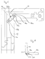
- Figure 1 shows a corner of a window frame. The remaining parts of the window frame are omitted for simplicity of illustration. Two frame parts 10, 12 off Wood are joined together on a miter cut 14. This corner joint will described in more detail below.
- a first bore 16 is guided in the frame part 10 (with dashed line shown). Analog is in the other frame part 12 another first bore 18 out.
- the connecting element 20 are introduced with its legs 22 in the first bore 16 and then then the leg 24 of the connecting element in the further first bore 18 in the other frame part 12, wherein initially roughly shown in Figure 1 Location is reached.
- Figure 1 also shows at the ends of the frame parts 10 and 12, respectively the cross section through the frame parts, wherein the cross sections "unfolded are ", that is, the actually perpendicular to the plane of the drawing guided cuts are Turned 90 ° so that they can be displayed in Figure 1.
- second holes 26 and 28 are provided, which are attached in Figure 1 perpendicular to the drawing plane and through the holes 16 or 18 go through and on the opposite side from the Bore emerge, but not go to the outer surface of the frame parts (see. FIG. 4).
- the second holes 26, 28 serve to receive dowel pins (not shown), which are driven into the bores 26, 28.
- holes (holes) 30, 32 formed, according to Figure 1 only approximately aligned with the said holes 26, 28 in the wood.
- the diameters the bores 26, 28, 30, 32 are equal and correspond to the diameters of (not shown) dowel pins.
- the dowel pins are made of metal, for example.
- FIG. 1 shows the condition of the corner joint during of the assembly, but before the final state, which reaches during assembly becomes.
- the offset shown in Figure 1 between said holes is so given given the dimensions of the components then, if the Frame parts on the miter cut 14 full but without special tension to each other lie.
- the connecting element 20 also exerts no strong force on the inner walls of the holes 16, 18 from. Described below Dowels, angle dowels or a so-called shape spring, can in This condition further stabilize the corner joint and in particular a rotation effect.
- the offset "E” describes the distance of the center axes of the two holes in the direction perpendicular to the associated first bore 16 or 18.
- the offset “F” describes the Distance between the center axes of the holes in the direction of the associated first bore 16 and 18, respectively, as shown in FIG.
- Figure 2 shows a section along the line I-II in Figure 1 with another embodiment of the connecting element 22a. While in the embodiment according to Figure 1, the connecting element is a piece of flat iron (see Figure 7, above), is at Embodiment of Figure 2, the connecting element 22a bolt-shaped, i. Has a circular cross section (see also Figure 7, center).
- Figure 2 still shows holes 42 for anchors, in the miter section provide an anti-rotation.
- FIG. 3 shows the drilling pattern in an end face of the frame parts 10 (the same applies to FIG the frame part 12) with the holes 16 (for the connecting element 20) and the Holes 42 for dowels (not shown).
- These holes can be extremely simple Be made without elaborate machines, for example, with a simple Template and a drilling tool.
- These works do not have to be high Demands on the accuracy and the machine cost of the manufacturer of the system but can easily be "on-site", ie for example, in a joinery or the like executed near the construction site become.
- Figure 4 shows a modified Bohrstory an end face of a frame part on the Gehrungsexcellent 14, wherein instead of the holes for the dowels in the embodiment 4, a slot-like milling 44 is provided, into which a plate can be inserted is, which analogous to the dowels causes a rotation.
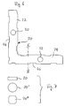
- Figure 5 shows a modified embodiment of a corner joint, wherein the Variation is essentially that the connecting element 20a not is angled. Accordingly, the holes 16a, 18a extend in the frame parts 10 or 12 coaxial.
- Figures 1 and 5 are mutually corresponding or function-like Components provided with the same reference numerals, supplemented in Figure 5 respectively with the addition "a”.
- Figure 6 shows an embodiment of a connecting element 20, as it is for Example used in Figure 1.
- Figure 7 shows different embodiments of cross sections of the connecting element 20 along the line III-IV of Figure 6.
- Figure 8 shows a modification of the embodiment shown in Figures 1 to 7 a corner joint to the effect that instead of a miter cut 14th a blunt shock 14a is provided between the frame parts 10a and 12a.
- Connecting element 20b analogous to the connecting element 20a according to Figure 5, connects the frame parts 10a, 12a at the joining surface 14a.
- the term "joint surface” So includes both a miter cut 14 ( Figure 1) and a connection surface 14a with a blunt impact according to FIG. 8.
- Holes 30b, 32b are indicated in FIG. The function corresponds to the extent of Figure 5 and its description.
Landscapes
- Engineering & Computer Science (AREA)
- Civil Engineering (AREA)
- Structural Engineering (AREA)
- Joining Of Corner Units Of Frames Or Wings (AREA)
- Securing Of Glass Panes Or The Like (AREA)
Abstract
Description
- erste Bohrungen in den Rahmenteilen, die von den Stirnflächen der Rahmenteile ausgehen,
- zumindest ein Verbindungselement aus einem Material, das härter ist als das Material der Rahmenteile und das in die ersten Bohrungen eingeführt ist,
- zweite Bohrungen in den Rahmenteilen, die senkrecht und zumindest bis zu den ersten Bohrungen verlaufen,
- Bohrungen in dem Verbindungselement, die bis auf einen vor dem Zusammenbau des Fensterrahmens gegebenen Versatz mit den zweiten Bohrungen fluchten, und
- Spannstifte, die in die zweiten Bohrungen und die Bohrungen in dem Verbindungselement eingetrieben sind und dabei den Versatz zumindest teilweise aufgehoben haben.
- Bereitstellen von Stangen, deren Profil dem der Rahmenteile des herzustellenden Fensterrahmens entspricht und deren Länge ein mehrfaches größer ist als die Länge eines Rahmenteiles,
- Schneiden der Stangen vor Ort in Rahmenteile,
- Bohren von ersten Bohrungen in die Stirnflächen der Rahmenteile,
- Bohren von zweiten Bohrungen in die Rahmenteile senkrecht und zumindest bis zu den ersten Bohrungen,
- Einsetzen von zumindest einem Verbindungselement aus einem Material, das härter ist als das Material der Rahmenteile, in die ersten Bohrungen, wobei das Verbindungselement Bohrungen aufweist, die nach dem Einsetzen des Verbindungselementes in die ersten Bohrungen einen Versatz in Bezug auf die zweiten Bohrungen aufweisen, und
- Eintreiben von Spannstiften in die zweiten Bohrungen und in die Bohrungen in dem Verbindungselement, um den Versatz zumindest im wesentlichen aufzuheben.
- Figur 1
- eine Draufsicht auf eine Fenster-Eckverbindung;
- Figur 2
- einen Schnitt durch ein Rahmenteil und ein Verbindungselement;
- Figur 3
- eine Draufsicht auf eine Stirnfläche eines Rahmenteiles am Gehrungsschnitt mit Bohrungen für das Verbindungselement und Dübel;
- Figur 4
- eine Stirnflächenansicht entsprechend Figur 3 mit einem gefrästen Schlitz anstelle der Dübel-Bohrungen;
- Figur 5
- eine Draufsicht auf ein weiteres Ausführungsbeispiel einer Eckverbindung;
- Figur 6
- ein Verbindungselement;
- Figur 7
- unterschiedliche Querschnitte eines Verbindungselements; und
- Figur 8
- eine Variante einer Fenster-Eckverbindung mit stumpfem Stoß oder einer Konterprofilierung.
Claims (11)
- Eckverbindung für einen Fensterrahmen oder dergleichen aus Holz, einem Holzwerkstoff oder Kunststoff, dessen Rahmenteile (10, 12) in der Ecke an einer Fügefläche (14, 14a) verbunden sind, gekennzeichnet durcherste Bohrungen (16, 18) in den Rahmenteilen (10, 12), die von den Stirnflächen der Fügefläche (14, 14a) ausgehen,zumindest ein Verbindungselement (20, 20a) aus einem Material, das härter ist als das Material der Rahmenteile (10, 12) und das in die ersten Bohrungen (16, 18) eingeführt ist,zweite Bohrungen (26, 28; 26a) in den Rahmenteilen (10, 12), die senkrecht und zumindest bis zu den ersten Bohrungen (16, 18) verlaufen,Bohrungen (30, 32; 30a) in dem Verbindungselement (20; 20a), die bis auf einen vor dem Zusammenbau des Fensterrahmens gegebenen Versatz (E, F; K) mit den zweiten Bohrungen (26, 28; 26a) fluchten, undSpannstifte, die in die zweiten Bohrungen (26, 28, 26a) und die Bohrungen (30, 32; 30a) in dem Verbindungselement (20; 20a) unter zumindest teilweiser Aufhebung des Versatzes eingetrieben sind.
- Eckverbindung gemäß Anspruch 1, dadurch gekennzeichnet, dass das Verbindungselement (20) zwei im rechten Winkel zueinander stehende Schenkel (22, 24) aufweist.
- Eckverbindung nach einem der Ansprüche 1 oder 2, gekennzeichnet durch dritte Bohrungen (34, 36; 34a, 36a) in den Rahmenteilen (10, 12), die bis zu den ersten Bohrungen (16, 18; 16a, 18a) führen, sodass ein Kleber durch eine der dritten Bohrungen in die ersten Bohrungen und daraus in eine andere der dritten Bohrungen pressbar ist.
- Eckverbindung nach einem der vorhergehenden Ansprüche, dadurch gekennzeichnet, dass das Verbindungselement (20; 20a) in jeder Richtung geringere Abmessungen hat als die ersten Bohrungen (16, 18; 16a, 18a).
- Eckverbindung nach einem der vorhergehenden Ansprüche, dadurch gekennzeichnet, dass das Verbindungselement (20; 20a) ein Stück Flachmetall ist.
- Eckverbindung nach einem der Ansprüche 1 bis 4, dadurch gekennzeichnet, dass das Verbindungselement bolzenförmige Teile hat.
- Eckverbindung nach einem der vorhergehenden Ansprüche, dadurch gekennzeichnet, dass der Versatz sowohl eine Komponente (E) senkrecht zur Richtung der ersten Bohrung (18) als auch eine Komponente (F) parallel zur Richtung der ersten Bohrung (18) hat.
- Eckverbindung nach einem der vorhergehenden Ansprüche, dadurch gekennzeichnet, dass der Versatz 0,3 bis 1 mm beträgt.
- Eckverbindung nach einem der vorhergehenden Ansprüche, dadurch gekennzeichnet, dass die Spannstifte einen Durchmesser haben, der den Durchmessern der zweiten Bohrungen (26, 28) und der Bohrungen (30, 32) im Verbindungselement (20) entspricht.
- Eckverbindung nach einem der vorhergehenden Ansprüche, gekennzeichnet durch Dübel und/oder Flachstücke, die als Verdrehsicherungen in die Stirnflächen des Gehrungsschnittes (14) eingefügt sind.
- Verfahren zum Herstellen eines Fensterrahmens oder dergleichen aus Holz, einem Holzwerkstoff oder Kunststoff, folgende Schritte umfassend:Bereitstellen von Stangen, deren Profil dem der Rahmenteile (10, 12) des herzustellenden Fensterrahmens entspricht und deren Länge ein mehrfaches größer ist als die Länge eines Rahmenteiles,Schneiden der Stangen auf Längen der Rahmenteile (10, 12) vor Ort,Bohren von ersten Bohrungen (16, 18) in die Stirnflächen der Rahmenteile (10, 12),Bohren von zweiten Bohrungen (26, 28) in die Rahmenteile (10, 12) senkrecht und zumindest bis zu den ersten Bohrungen (16, 18),Einsetzen von zumindest einem Verbindungselement (20) aus einem Material, das härter ist als das Material der Rahmenteile in die ersten Bohrungen, wobei das Verbindungselement Bohrungen (30, 32) aufweist, die nach dem Einsetzen des Verbindungselementes in die ersten Bohrungen einen Versatz (E, F, K) in Bezug auf die zweiten Bohrungen (26, 28) aufweisen, undEintreiben von Spannstiften in die zweiten Bohrungen (26, 28), und in die Bohrungen (30, 32) in dem Verbindungselement, um den Versatz zumindest im wesentlichen aufzuheben.
Priority Applications (5)
| Application Number | Priority Date | Filing Date | Title |
|---|---|---|---|
| PL04006310T PL1577482T3 (pl) | 2004-03-16 | 2004-03-16 | Połączenie narożne ram okiennych i tym podobnych |
| DE502004003754T DE502004003754D1 (de) | 2004-03-16 | 2004-03-16 | Eckverbindung für einen Fensterrahmen oder dergleichen |
| AT04006310T ATE362031T1 (de) | 2004-03-16 | 2004-03-16 | Eckverbindung für einen fensterrahmen oder dergleichen |
| EP04006310A EP1577482B1 (de) | 2004-03-16 | 2004-03-16 | Eckverbindung für einen Fensterrahmen oder dergleichen |
| ES04006310T ES2285297T3 (es) | 2004-03-16 | 2004-03-16 | Elemento de union angular para un marco de ventana o similar. |
Applications Claiming Priority (1)
| Application Number | Priority Date | Filing Date | Title |
|---|---|---|---|
| EP04006310A EP1577482B1 (de) | 2004-03-16 | 2004-03-16 | Eckverbindung für einen Fensterrahmen oder dergleichen |
Publications (2)
| Publication Number | Publication Date |
|---|---|
| EP1577482A1 true EP1577482A1 (de) | 2005-09-21 |
| EP1577482B1 EP1577482B1 (de) | 2007-05-09 |
Family
ID=34833617
Family Applications (1)
| Application Number | Title | Priority Date | Filing Date |
|---|---|---|---|
| EP04006310A Expired - Lifetime EP1577482B1 (de) | 2004-03-16 | 2004-03-16 | Eckverbindung für einen Fensterrahmen oder dergleichen |
Country Status (5)
| Country | Link |
|---|---|
| EP (1) | EP1577482B1 (de) |
| AT (1) | ATE362031T1 (de) |
| DE (1) | DE502004003754D1 (de) |
| ES (1) | ES2285297T3 (de) |
| PL (1) | PL1577482T3 (de) |
Cited By (3)
| Publication number | Priority date | Publication date | Assignee | Title |
|---|---|---|---|---|
| CN101936111A (zh) * | 2010-08-06 | 2011-01-05 | 中国二十二冶集团有限公司 | 塑钢连接角码拼装外窗钢副框的外窗施工工艺 |
| CN109989686A (zh) * | 2019-04-01 | 2019-07-09 | 施万库 | 一种防风防水注胶角码及其连接结构 |
| CN116345114A (zh) * | 2023-05-10 | 2023-06-27 | 江苏新扬新材料股份有限公司 | 一种用于天线骨架位置精度调节的定位连接装置及其制作连接方法 |
Families Citing this family (1)
| Publication number | Priority date | Publication date | Assignee | Title |
|---|---|---|---|---|
| CN103867087B (zh) * | 2014-03-18 | 2016-01-20 | 浙江中南建设集团有限公司 | 一种活动注胶式组角片装置 |
Citations (3)
| Publication number | Priority date | Publication date | Assignee | Title |
|---|---|---|---|---|
| FR2299490A1 (fr) * | 1975-01-28 | 1976-08-27 | Schock & Co Gmbh | Profile pour la fabrication d |
| DE3229390A1 (de) * | 1981-09-28 | 1983-05-05 | Faipari Kutató Intézet, Budapest | Rahmen aus stabartigen elementarteilen, hauptsaechlich fuer fensterrahmen und fensterfluegel |
| DE20114224U1 (de) * | 2001-08-29 | 2002-01-17 | Schüco International KG, 33609 Bielefeld | Vorrichtung zur Verbindung von Hohlprofilen zu Rahmenteilen |
-
2004
- 2004-03-16 AT AT04006310T patent/ATE362031T1/de not_active IP Right Cessation
- 2004-03-16 DE DE502004003754T patent/DE502004003754D1/de not_active Expired - Fee Related
- 2004-03-16 ES ES04006310T patent/ES2285297T3/es not_active Expired - Lifetime
- 2004-03-16 PL PL04006310T patent/PL1577482T3/pl unknown
- 2004-03-16 EP EP04006310A patent/EP1577482B1/de not_active Expired - Lifetime
Patent Citations (3)
| Publication number | Priority date | Publication date | Assignee | Title |
|---|---|---|---|---|
| FR2299490A1 (fr) * | 1975-01-28 | 1976-08-27 | Schock & Co Gmbh | Profile pour la fabrication d |
| DE3229390A1 (de) * | 1981-09-28 | 1983-05-05 | Faipari Kutató Intézet, Budapest | Rahmen aus stabartigen elementarteilen, hauptsaechlich fuer fensterrahmen und fensterfluegel |
| DE20114224U1 (de) * | 2001-08-29 | 2002-01-17 | Schüco International KG, 33609 Bielefeld | Vorrichtung zur Verbindung von Hohlprofilen zu Rahmenteilen |
Cited By (4)
| Publication number | Priority date | Publication date | Assignee | Title |
|---|---|---|---|---|
| CN101936111A (zh) * | 2010-08-06 | 2011-01-05 | 中国二十二冶集团有限公司 | 塑钢连接角码拼装外窗钢副框的外窗施工工艺 |
| CN109989686A (zh) * | 2019-04-01 | 2019-07-09 | 施万库 | 一种防风防水注胶角码及其连接结构 |
| CN116345114A (zh) * | 2023-05-10 | 2023-06-27 | 江苏新扬新材料股份有限公司 | 一种用于天线骨架位置精度调节的定位连接装置及其制作连接方法 |
| CN116345114B (zh) * | 2023-05-10 | 2025-12-02 | 江苏新扬新材料股份有限公司 | 一种用于天线骨架位置精度调节的定位连接装置的制作连接方法 |
Also Published As
| Publication number | Publication date |
|---|---|
| ES2285297T3 (es) | 2007-11-16 |
| EP1577482B1 (de) | 2007-05-09 |
| PL1577482T3 (pl) | 2007-08-31 |
| ATE362031T1 (de) | 2007-06-15 |
| DE502004003754D1 (de) | 2007-06-21 |
Similar Documents
| Publication | Publication Date | Title |
|---|---|---|
| DE102010062751A1 (de) | Eckverbindungsvorrichtung für Profile | |
| EP3433440B1 (de) | Verfahren zum verbinden von balken aus holzwerkstoff | |
| EP2894024A1 (de) | Zweiteiliges Eckschweißverbinderelement und Fertigungsverfahren für die Herstellung von Fenster- und Türrahmen aus Kunststoffhohlprofilen | |
| DE19724285A1 (de) | Verfahren zum Verbinden von wenigstens zwei Holzbauteilen sowie Verbindungselement zur Durchführung des Verfahrens | |
| DE2646351A1 (de) | Verfahren zur herstellung einer geleimten duebelverbindung mehrerer holzteile | |
| DE19539862C2 (de) | Eckverbindung für Hohlprofilstäbe zur Bildung von Rahmenteilen | |
| EP1577482B1 (de) | Eckverbindung für einen Fensterrahmen oder dergleichen | |
| EP0898086B1 (de) | Verbindungselement | |
| DE4131903C2 (de) | Vorrichtung zum Parallelverbinden von zwei Konstruktionsprofilen | |
| DE20114224U1 (de) | Vorrichtung zur Verbindung von Hohlprofilen zu Rahmenteilen | |
| DE2053058A1 (de) | Rahmen mit als Hohlprofil ausgeführten Rahmenelementen | |
| DE1528345C3 (de) | Verbindungsleiste aus Kunststoff oder Metall zum Verbinden von zwei mit Holzleim zu verleimenden Holzteilen | |
| DE10318652B3 (de) | Bohrfreie Verbindungsvorrichtung | |
| EP3916188B1 (de) | Verbindungsvorrichtung zur verbindung von zwei bauelementen im stossbereich des türen- oder fensterbaues, sowie verfahren zur herstellung einer solchen gehrungsverbindung an zwei bauelementen | |
| DE10155632C1 (de) | Rahmengestell für einen Schaltschrank | |
| EP1813824A2 (de) | Verbindungsvorrichtung für Möbelplatten | |
| DE2452054B2 (de) | Quer zueinander stehendes Paar von Platten aus Holz, Holzspänen o.dgl. mit einer Verbindungsvorrichtung | |
| DE1954810C3 (de) | Beschlag zum lösbaren Verbinden zweier senkrecht aufeinanderstoßender plattenförmiger Bauteile, insbesondere Möbelteile | |
| DE2149422C3 (de) | Eckverbindung von Rahmenteilen, die zu Rahmen von Fenstern, Türen od.dgl. zusammengesetzt sind | |
| DE202004004696U1 (de) | Verbindungszapfen | |
| EP1039152B1 (de) | Schraube zur gegenseitigen Verbindung von stumpf oder in einem Gehrungsschnitt aneinander anliegenden oder aneinander anstossenden Holzprofilen | |
| DE202007007888U1 (de) | Element und System zum Aufbau von Vorrichtungen zum Aufspannen von Werkstücken | |
| AT508700A1 (de) | Eckverbindung | |
| AT508762A4 (de) | Lösbare verbindung zwischen einem hohlprofil und einem weiteren profil | |
| EP1605172B1 (de) | Beschlag zum Verbinden eines länglichen und eines flächigen Bauteils |
Legal Events
| Date | Code | Title | Description |
|---|---|---|---|
| PUAI | Public reference made under article 153(3) epc to a published international application that has entered the european phase |
Free format text: ORIGINAL CODE: 0009012 |
|
| 17P | Request for examination filed |
Effective date: 20050617 |
|
| AK | Designated contracting states |
Kind code of ref document: A1 Designated state(s): AT BE BG CH CY CZ DE DK EE ES FI FR GB GR HU IE IT LI LU MC NL PL PT RO SE SI SK TR |
|
| AX | Request for extension of the european patent |
Extension state: AL LT LV MK |
|
| AKX | Designation fees paid |
Designated state(s): AT BE BG CH CY CZ DE DK EE ES FI FR GB GR HU IE IT LI LU MC NL PL PT RO SE SI SK TR |
|
| GRAP | Despatch of communication of intention to grant a patent |
Free format text: ORIGINAL CODE: EPIDOSNIGR1 |
|
| GRAS | Grant fee paid |
Free format text: ORIGINAL CODE: EPIDOSNIGR3 |
|
| GRAA | (expected) grant |
Free format text: ORIGINAL CODE: 0009210 |
|
| AK | Designated contracting states |
Kind code of ref document: B1 Designated state(s): AT BE BG CH CY CZ DE DK EE ES FI FR GB GR HU IE IT LI LU MC NL PL PT RO SE SI SK TR |
|
| PG25 | Lapsed in a contracting state [announced via postgrant information from national office to epo] |
Ref country code: FI Free format text: LAPSE BECAUSE OF FAILURE TO SUBMIT A TRANSLATION OF THE DESCRIPTION OR TO PAY THE FEE WITHIN THE PRESCRIBED TIME-LIMIT Effective date: 20070509 |
|
| REG | Reference to a national code |
Ref country code: GB Ref legal event code: FG4D Free format text: NOT ENGLISH |
|
| REG | Reference to a national code |
Ref country code: CH Ref legal event code: EP |
|
| REG | Reference to a national code |
Ref country code: IE Ref legal event code: FG4D Free format text: LANGUAGE OF EP DOCUMENT: GERMAN |
|
| REF | Corresponds to: |
Ref document number: 502004003754 Country of ref document: DE Date of ref document: 20070621 Kind code of ref document: P |
|
| PG25 | Lapsed in a contracting state [announced via postgrant information from national office to epo] |
Ref country code: SE Free format text: LAPSE BECAUSE OF FAILURE TO SUBMIT A TRANSLATION OF THE DESCRIPTION OR TO PAY THE FEE WITHIN THE PRESCRIBED TIME-LIMIT Effective date: 20070809 |
|
| REG | Reference to a national code |
Ref country code: PL Ref legal event code: T3 |
|
| ET | Fr: translation filed | ||
| REG | Reference to a national code |
Ref country code: ES Ref legal event code: FG2A Ref document number: 2285297 Country of ref document: ES Kind code of ref document: T3 |
|
| GBV | Gb: ep patent (uk) treated as always having been void in accordance with gb section 77(7)/1977 [no translation filed] |
Effective date: 20070509 |
|
| REG | Reference to a national code |
Ref country code: IE Ref legal event code: FD4D |
|
| PG25 | Lapsed in a contracting state [announced via postgrant information from national office to epo] |
Ref country code: DK Free format text: LAPSE BECAUSE OF FAILURE TO SUBMIT A TRANSLATION OF THE DESCRIPTION OR TO PAY THE FEE WITHIN THE PRESCRIBED TIME-LIMIT Effective date: 20070509 Ref country code: PT Free format text: LAPSE BECAUSE OF FAILURE TO SUBMIT A TRANSLATION OF THE DESCRIPTION OR TO PAY THE FEE WITHIN THE PRESCRIBED TIME-LIMIT Effective date: 20071009 Ref country code: SI Free format text: LAPSE BECAUSE OF FAILURE TO SUBMIT A TRANSLATION OF THE DESCRIPTION OR TO PAY THE FEE WITHIN THE PRESCRIBED TIME-LIMIT Effective date: 20070509 Ref country code: BG Free format text: LAPSE BECAUSE OF FAILURE TO SUBMIT A TRANSLATION OF THE DESCRIPTION OR TO PAY THE FEE WITHIN THE PRESCRIBED TIME-LIMIT Effective date: 20070809 Ref country code: IE Free format text: LAPSE BECAUSE OF FAILURE TO SUBMIT A TRANSLATION OF THE DESCRIPTION OR TO PAY THE FEE WITHIN THE PRESCRIBED TIME-LIMIT Effective date: 20070509 Ref country code: CZ Free format text: LAPSE BECAUSE OF FAILURE TO SUBMIT A TRANSLATION OF THE DESCRIPTION OR TO PAY THE FEE WITHIN THE PRESCRIBED TIME-LIMIT Effective date: 20070509 |
|
| PG25 | Lapsed in a contracting state [announced via postgrant information from national office to epo] |
Ref country code: SK Free format text: LAPSE BECAUSE OF FAILURE TO SUBMIT A TRANSLATION OF THE DESCRIPTION OR TO PAY THE FEE WITHIN THE PRESCRIBED TIME-LIMIT Effective date: 20070509 |
|
| PLBE | No opposition filed within time limit |
Free format text: ORIGINAL CODE: 0009261 |
|
| STAA | Information on the status of an ep patent application or granted ep patent |
Free format text: STATUS: NO OPPOSITION FILED WITHIN TIME LIMIT |
|
| 26N | No opposition filed |
Effective date: 20080212 |
|
| PG25 | Lapsed in a contracting state [announced via postgrant information from national office to epo] |
Ref country code: GB Free format text: LAPSE BECAUSE OF FAILURE TO SUBMIT A TRANSLATION OF THE DESCRIPTION OR TO PAY THE FEE WITHIN THE PRESCRIBED TIME-LIMIT Effective date: 20070509 Ref country code: GR Free format text: LAPSE BECAUSE OF FAILURE TO SUBMIT A TRANSLATION OF THE DESCRIPTION OR TO PAY THE FEE WITHIN THE PRESCRIBED TIME-LIMIT Effective date: 20070810 |
|
| PGFP | Annual fee paid to national office [announced via postgrant information from national office to epo] |
Ref country code: CH Payment date: 20080319 Year of fee payment: 5 Ref country code: ES Payment date: 20080328 Year of fee payment: 5 |
|
| PG25 | Lapsed in a contracting state [announced via postgrant information from national office to epo] |
Ref country code: RO Free format text: LAPSE BECAUSE OF FAILURE TO SUBMIT A TRANSLATION OF THE DESCRIPTION OR TO PAY THE FEE WITHIN THE PRESCRIBED TIME-LIMIT Effective date: 20070509 |
|
| PGFP | Annual fee paid to national office [announced via postgrant information from national office to epo] |
Ref country code: IT Payment date: 20080322 Year of fee payment: 5 Ref country code: LU Payment date: 20080314 Year of fee payment: 5 Ref country code: NL Payment date: 20080318 Year of fee payment: 5 Ref country code: PL Payment date: 20080307 Year of fee payment: 5 |
|
| PGFP | Annual fee paid to national office [announced via postgrant information from national office to epo] |
Ref country code: AT Payment date: 20080317 Year of fee payment: 5 |
|
| PGFP | Annual fee paid to national office [announced via postgrant information from national office to epo] |
Ref country code: DE Payment date: 20080326 Year of fee payment: 5 Ref country code: FR Payment date: 20080313 Year of fee payment: 5 |
|
| PGFP | Annual fee paid to national office [announced via postgrant information from national office to epo] |
Ref country code: BE Payment date: 20080430 Year of fee payment: 5 |
|
| PG25 | Lapsed in a contracting state [announced via postgrant information from national office to epo] |
Ref country code: MC Free format text: LAPSE BECAUSE OF NON-PAYMENT OF DUE FEES Effective date: 20080331 |
|
| PG25 | Lapsed in a contracting state [announced via postgrant information from national office to epo] |
Ref country code: EE Free format text: LAPSE BECAUSE OF FAILURE TO SUBMIT A TRANSLATION OF THE DESCRIPTION OR TO PAY THE FEE WITHIN THE PRESCRIBED TIME-LIMIT Effective date: 20070509 |
|
| PG25 | Lapsed in a contracting state [announced via postgrant information from national office to epo] |
Ref country code: CY Free format text: LAPSE BECAUSE OF FAILURE TO SUBMIT A TRANSLATION OF THE DESCRIPTION OR TO PAY THE FEE WITHIN THE PRESCRIBED TIME-LIMIT Effective date: 20070509 |
|
| BERE | Be: lapsed |
Owner name: UNILUX A.G. Effective date: 20090331 |
|
| PG25 | Lapsed in a contracting state [announced via postgrant information from national office to epo] |
Ref country code: AT Free format text: LAPSE BECAUSE OF NON-PAYMENT OF DUE FEES Effective date: 20090316 |
|
| REG | Reference to a national code |
Ref country code: CH Ref legal event code: PL |
|
| NLV4 | Nl: lapsed or anulled due to non-payment of the annual fee |
Effective date: 20091001 |
|
| REG | Reference to a national code |
Ref country code: FR Ref legal event code: ST Effective date: 20091130 |
|
| PG25 | Lapsed in a contracting state [announced via postgrant information from national office to epo] |
Ref country code: CH Free format text: LAPSE BECAUSE OF NON-PAYMENT OF DUE FEES Effective date: 20090331 Ref country code: LI Free format text: LAPSE BECAUSE OF NON-PAYMENT OF DUE FEES Effective date: 20090331 Ref country code: DE Free format text: LAPSE BECAUSE OF NON-PAYMENT OF DUE FEES Effective date: 20091001 |
|
| PG25 | Lapsed in a contracting state [announced via postgrant information from national office to epo] |
Ref country code: BE Free format text: LAPSE BECAUSE OF NON-PAYMENT OF DUE FEES Effective date: 20090331 Ref country code: NL Free format text: LAPSE BECAUSE OF NON-PAYMENT OF DUE FEES Effective date: 20091001 |
|
| PG25 | Lapsed in a contracting state [announced via postgrant information from national office to epo] |
Ref country code: FR Free format text: LAPSE BECAUSE OF NON-PAYMENT OF DUE FEES Effective date: 20091123 |
|
| REG | Reference to a national code |
Ref country code: ES Ref legal event code: FD2A Effective date: 20090317 |
|
| PG25 | Lapsed in a contracting state [announced via postgrant information from national office to epo] |
Ref country code: ES Free format text: LAPSE BECAUSE OF NON-PAYMENT OF DUE FEES Effective date: 20090317 Ref country code: HU Free format text: LAPSE BECAUSE OF FAILURE TO SUBMIT A TRANSLATION OF THE DESCRIPTION OR TO PAY THE FEE WITHIN THE PRESCRIBED TIME-LIMIT Effective date: 20071110 |
|
| REG | Reference to a national code |
Ref country code: PL Ref legal event code: LAPE |
|
| PG25 | Lapsed in a contracting state [announced via postgrant information from national office to epo] |
Ref country code: TR Free format text: LAPSE BECAUSE OF FAILURE TO SUBMIT A TRANSLATION OF THE DESCRIPTION OR TO PAY THE FEE WITHIN THE PRESCRIBED TIME-LIMIT Effective date: 20070509 Ref country code: PL Free format text: LAPSE BECAUSE OF NON-PAYMENT OF DUE FEES Effective date: 20090316 |
|
| PG25 | Lapsed in a contracting state [announced via postgrant information from national office to epo] |
Ref country code: IT Free format text: LAPSE BECAUSE OF NON-PAYMENT OF DUE FEES Effective date: 20090316 |
|
| PG25 | Lapsed in a contracting state [announced via postgrant information from national office to epo] |
Ref country code: LU Free format text: LAPSE BECAUSE OF NON-PAYMENT OF DUE FEES Effective date: 20090316 |