EP1577482A1 - Corner joint for window frames or the like - Google Patents
Corner joint for window frames or the like Download PDFInfo
- Publication number
- EP1577482A1 EP1577482A1 EP04006310A EP04006310A EP1577482A1 EP 1577482 A1 EP1577482 A1 EP 1577482A1 EP 04006310 A EP04006310 A EP 04006310A EP 04006310 A EP04006310 A EP 04006310A EP 1577482 A1 EP1577482 A1 EP 1577482A1
- Authority
- EP
- European Patent Office
- Prior art keywords
- bores
- connecting element
- holes
- frame parts
- corner joint
- Prior art date
- Legal status (The legal status is an assumption and is not a legal conclusion. Google has not performed a legal analysis and makes no representation as to the accuracy of the status listed.)
- Granted
Links
Images


Classifications
-
- E—FIXED CONSTRUCTIONS
- E06—DOORS, WINDOWS, SHUTTERS, OR ROLLER BLINDS IN GENERAL; LADDERS
- E06B—FIXED OR MOVABLE CLOSURES FOR OPENINGS IN BUILDINGS, VEHICLES, FENCES OR LIKE ENCLOSURES IN GENERAL, e.g. DOORS, WINDOWS, BLINDS, GATES
- E06B3/00—Window sashes, door leaves, or like elements for closing wall or like openings; Layout of fixed or moving closures, e.g. windows in wall or like openings; Features of rigidly-mounted outer frames relating to the mounting of wing frames
- E06B3/96—Corner joints or edge joints for windows, doors, or the like frames or wings
- E06B3/964—Corner joints or edge joints for windows, doors, or the like frames or wings using separate connection pieces, e.g. T-connection pieces
- E06B3/968—Corner joints or edge joints for windows, doors, or the like frames or wings using separate connection pieces, e.g. T-connection pieces characterised by the way the connecting pieces are fixed in or on the frame members
- E06B3/9681—Corner joints or edge joints for windows, doors, or the like frames or wings using separate connection pieces, e.g. T-connection pieces characterised by the way the connecting pieces are fixed in or on the frame members by press fit or adhesion
-
- E—FIXED CONSTRUCTIONS
- E06—DOORS, WINDOWS, SHUTTERS, OR ROLLER BLINDS IN GENERAL; LADDERS
- E06B—FIXED OR MOVABLE CLOSURES FOR OPENINGS IN BUILDINGS, VEHICLES, FENCES OR LIKE ENCLOSURES IN GENERAL, e.g. DOORS, WINDOWS, BLINDS, GATES
- E06B3/00—Window sashes, door leaves, or like elements for closing wall or like openings; Layout of fixed or moving closures, e.g. windows in wall or like openings; Features of rigidly-mounted outer frames relating to the mounting of wing frames
- E06B3/96—Corner joints or edge joints for windows, doors, or the like frames or wings
- E06B3/964—Corner joints or edge joints for windows, doors, or the like frames or wings using separate connection pieces, e.g. T-connection pieces
- E06B3/968—Corner joints or edge joints for windows, doors, or the like frames or wings using separate connection pieces, e.g. T-connection pieces characterised by the way the connecting pieces are fixed in or on the frame members
- E06B3/98—Corner joints or edge joints for windows, doors, or the like frames or wings using separate connection pieces, e.g. T-connection pieces characterised by the way the connecting pieces are fixed in or on the frame members the connecting pieces being specially adapted for drawing the frame members towards each other
- E06B3/982—Mitre joints
Definitions
- the invention relates to a corner joint for a window frame or the like made of wood, a wooden material or plastic.
- corner joints with counter-milling and dowel connection also require elaborate milling and the frame must be pressed. Again, it is a subsequent surface treatment usually required.
- the invention is based on the object, a corner joint for window frames or the like, such as door frames, frames, or larger Picture frame, provide that can be produced with relatively little effort and nevertheless allows tailor-made and long-term stable results.
- the corner joint according to the invention should be suitable for relative slim frame parts.
- the corner joint according to the invention is intended in particular be suitable as so-called "system commodity", i. one manufacturer does not supply one prefabricated windows on the construction site or in the warehouse, rather, the manufacturer delivers Components ("systemware") cut on site to those dimensions which are required for the given construction site. So, for example supplied as “systemware” elongated rods, the desired profile of the have to be produced window, but are much longer than the ultimate needed frame parts for the windows. On site, for example in a carpentry, can then cut the desired frame parts and put together become. The same applies to other window components, such as seals etc.
- the present invention is particularly suitable for such "systemware”.
- This corner joint does not require expensive machines and aids, in particular no milling machine, no frame press and no elaborate Connecting the frames with screw clamps.
- the processing is fast and does not necessarily require a gluing.
- the corner joint is characterized a high accuracy of fit of the components and a high long-term stability out. Perfect fit here means that the assembled components are structurally geometrical exactly in the desired position to each other, i. e. at the connection points There are no unwanted protrusions and edges and also the optical and haptic impression are high quality. The ingress of moisture is largely prevented.
- said connecting element two legs at right angles to each other.
- the connecting element be an elongated bar without bending.
- the cross section of the connecting element assume different shapes perpendicular to its longitudinal axis, For example, a relatively flat rectangular shape, or the shape of a circle or also, for example, the shape of a square with rounded or bevelled edges.
- a particularly preferred embodiment of the invention provides third holes in the frame parts that lead to the first holes, so that an adhesive through one of the third holes in the first holes and from there into another the third holes is pressed. It turned out that with adhesives one very intimate connection between the connecting part and the wood or wood material is achieved, so that of the connecting element on the wood or the wood material applied force is distributed over a relatively large area, and the Connecting element not or only insignificantly pushes into the wood, and indeed then, when the resulting forces in the assembly of the window frame at Compensation of the offset arise.
- known metal frames are in there anyway existing cavities corner joints braced, the metal being the resulting Absorbs forces without further ado.
- a simple assembly of the window frame and also a particularly favorable Distribution of the adhesive for the purpose of a uniform distribution of force in the wood is also promoted by the fact that the connecting element according to another preferred Embodiment of the invention has smaller dimensions than the holes, in which it is inserted. In this way, the adhesive around the connecting element and anchor it on all sides firmly in the wood material.
- the said Inventive offset both a component perpendicular to the direction the bore in which the connecting element is inserted, as well as a component parallel to the direction of this hole.
- the "direction of the hole” is the direction its longitudinal axis.
- the dowel pins which are driven into the holes in the wood and in the connecting element, in Diameter the same size as the mentioned holes.
- the connecting element is generally made of a material that is harder than the wood, the wood material or the plastic of the window frame parts, so for example a metal, such as aluminum, steel or stainless steel. But they are also high-strength Plastics conceivable as a material for the connecting element.
- dowels and / or flat pieces as anti-rotation and / or positioning aid in the end faces of the miter cut inserted dowels and / or flat pieces as anti-rotation and / or positioning aid in the end faces of the miter cut inserted.
- the corner joint according to the invention is particularly suitable for mitred cut frame parts.
- the above-mentioned advantages will also be partially realized in a corner joint, a blunt bump or a Has counter profiling.
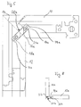
- Figure 1 shows a corner of a window frame. The remaining parts of the window frame are omitted for simplicity of illustration. Two frame parts 10, 12 off Wood are joined together on a miter cut 14. This corner joint will described in more detail below.
- a first bore 16 is guided in the frame part 10 (with dashed line shown). Analog is in the other frame part 12 another first bore 18 out.
- the connecting element 20 are introduced with its legs 22 in the first bore 16 and then then the leg 24 of the connecting element in the further first bore 18 in the other frame part 12, wherein initially roughly shown in Figure 1 Location is reached.
- Figure 1 also shows at the ends of the frame parts 10 and 12, respectively the cross section through the frame parts, wherein the cross sections "unfolded are ", that is, the actually perpendicular to the plane of the drawing guided cuts are Turned 90 ° so that they can be displayed in Figure 1.
- second holes 26 and 28 are provided, which are attached in Figure 1 perpendicular to the drawing plane and through the holes 16 or 18 go through and on the opposite side from the Bore emerge, but not go to the outer surface of the frame parts (see. FIG. 4).
- the second holes 26, 28 serve to receive dowel pins (not shown), which are driven into the bores 26, 28.
- holes (holes) 30, 32 formed, according to Figure 1 only approximately aligned with the said holes 26, 28 in the wood.
- the diameters the bores 26, 28, 30, 32 are equal and correspond to the diameters of (not shown) dowel pins.
- the dowel pins are made of metal, for example.
- FIG. 1 shows the condition of the corner joint during of the assembly, but before the final state, which reaches during assembly becomes.
- the offset shown in Figure 1 between said holes is so given given the dimensions of the components then, if the Frame parts on the miter cut 14 full but without special tension to each other lie.
- the connecting element 20 also exerts no strong force on the inner walls of the holes 16, 18 from. Described below Dowels, angle dowels or a so-called shape spring, can in This condition further stabilize the corner joint and in particular a rotation effect.
- the offset "E” describes the distance of the center axes of the two holes in the direction perpendicular to the associated first bore 16 or 18.
- the offset “F” describes the Distance between the center axes of the holes in the direction of the associated first bore 16 and 18, respectively, as shown in FIG.
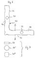
- Figure 2 shows a section along the line I-II in Figure 1 with another embodiment of the connecting element 22a. While in the embodiment according to Figure 1, the connecting element is a piece of flat iron (see Figure 7, above), is at Embodiment of Figure 2, the connecting element 22a bolt-shaped, i. Has a circular cross section (see also Figure 7, center).
- Figure 2 still shows holes 42 for anchors, in the miter section provide an anti-rotation.
- FIG. 3 shows the drilling pattern in an end face of the frame parts 10 (the same applies to FIG the frame part 12) with the holes 16 (for the connecting element 20) and the Holes 42 for dowels (not shown).
- These holes can be extremely simple Be made without elaborate machines, for example, with a simple Template and a drilling tool.
- These works do not have to be high Demands on the accuracy and the machine cost of the manufacturer of the system but can easily be "on-site", ie for example, in a joinery or the like executed near the construction site become.
- Figure 4 shows a modified Bohrstory an end face of a frame part on the Gehrungsexcellent 14, wherein instead of the holes for the dowels in the embodiment 4, a slot-like milling 44 is provided, into which a plate can be inserted is, which analogous to the dowels causes a rotation.
- Figure 5 shows a modified embodiment of a corner joint, wherein the Variation is essentially that the connecting element 20a not is angled. Accordingly, the holes 16a, 18a extend in the frame parts 10 or 12 coaxial.
- Figures 1 and 5 are mutually corresponding or function-like Components provided with the same reference numerals, supplemented in Figure 5 respectively with the addition "a”.
- Figure 6 shows an embodiment of a connecting element 20, as it is for Example used in Figure 1.
- Figure 7 shows different embodiments of cross sections of the connecting element 20 along the line III-IV of Figure 6.
- Figure 8 shows a modification of the embodiment shown in Figures 1 to 7 a corner joint to the effect that instead of a miter cut 14th a blunt shock 14a is provided between the frame parts 10a and 12a.
- Connecting element 20b analogous to the connecting element 20a according to Figure 5, connects the frame parts 10a, 12a at the joining surface 14a.
- the term "joint surface” So includes both a miter cut 14 ( Figure 1) and a connection surface 14a with a blunt impact according to FIG. 8.
- Holes 30b, 32b are indicated in FIG. The function corresponds to the extent of Figure 5 and its description.
Landscapes
- Engineering & Computer Science (AREA)
- Civil Engineering (AREA)
- Structural Engineering (AREA)
- Joining Of Corner Units Of Frames Or Wings (AREA)
- Securing Of Glass Panes Or The Like (AREA)
Abstract
Description
Die Erfindung betrifft eine Eckverbindung für einen Fensterrahmen oder dergleichen aus Holz, einem Holzwerkstoff oder Kunststoff.The invention relates to a corner joint for a window frame or the like made of wood, a wooden material or plastic.
Der Stand der Technik kennt bei Holzrahmen von Fenstern unterschiedliche Eckverbindungen, zum Beispiel sogenannte Schlitz- und Zapfenverbindungen, Konterfräsungen mit Dübelverbindung und Gehrungsschnitte mit Dübelverbindung. Diese bekannten Eckverbindungen haben aber unterschiedliche Nachteile.The state of the art knows different corner joints in wooden frames of windows, for example, so-called slot and tenon joints, counter-milling with dowel connection and miter cuts with dowel connection. These However, known corner joints have different disadvantages.
Die Schlitz- und Zapfenverbindung erfordert, dass die Rahmenprofile mit aufwendigen Konterfräsungen versehen werden. Die zusammengefügten Rahmenteile müssen verpresst werden. Beide genannten Arbeitsschritte verlangen relativ hohen Aufwand hinsichtlich der Maschinen und deren Bedienung. Darüber hinaus verlangt diese Technik auch in aller Regel eine abschließende Oberflächenbehandlung der Hölzer.The slot and tenon connection requires that the frame profiles with elaborate Counter-milling be provided. The assembled frame parts must be pressed. Both steps mentioned require relatively high effort in terms of machines and their operation. In addition, this requires Technique also usually a final surface treatment of the woods.
Die Eckverbindungen mit Konterfräsung und Dübelverbindung erfordern ebenfalls aufwendige Fräsarbeiten und die Rahmen müssen gepresst werden. Auch ist wiederum eine anschließende Oberflächenbehandlung in aller Regel erforderlich.The corner joints with counter-milling and dowel connection also require elaborate milling and the frame must be pressed. Again, it is a subsequent surface treatment usually required.
Die einfache Verbindung mit Gehrungsschnitt und Dübelverbindung ist zwar relativ wenig aufwendig, jedoch müssen auch hier die Rahmen gepresst werden.The simple connection with miter cut and dowel connection is relative not very costly, but here too the frames have to be pressed.
Auch die im Stand der Technik bekannte Eckverbindung mit Dübel und sogenannten Schwalben liefert hinsichtlich der Stabilität häufig wenig zufriedenstellende Ergebnisse. Auch sind der Arbeitsaufwand und der Maschinenaufwand erheblich.Also known in the art Eckverbindung with dowels and so-called Swallows often provide unsatisfactory results in terms of stability. Also, the workload and the machine cost are significant.
Der Erfindung liegt die Aufgabe zugrunde, eine Eckverbindung für Fensterrahmen oder dergleichen, wie zum Beispiel Türrahmen, Blendrahmen, oder auch größere Bilderrahmen, bereitzustellen, die mit relative geringem Aufwand herstellbar ist und gleichwohl passgenaue und langzeitstabile Ergebnisse ermöglicht. The invention is based on the object, a corner joint for window frames or the like, such as door frames, frames, or larger Picture frame, provide that can be produced with relatively little effort and nevertheless allows tailor-made and long-term stable results.
Insbesondere soll die erfindungsgemäße Eckverbindung geeignet sein für relativ schlanke Rahmenteile. Weiterhin soll die erfindungsgemäße Eckverbindung insbesondere geeignet sein als sogenannte "Systemware", d.h. ein Hersteller liefert keine fertig montierten Fenster auf die Baustelle oder in die Lager, vielmehr liefert der Hersteller Komponenten ("Systemware"), die vor Ort auf diejenigen Maße geschnitten werden, die für die gegebene Baustelle erforderlich sind. Also werden zum Beispiel als "Systemware" langgestreckte Stangen geliefert, die das gewünschte Profil der herzustellenden Fenster aufweisen, jedoch wesentlich länger sind als die letztlich benötigten Rahmenteile für die Fenster. Vor Ort, also zum Beispiel in einer Schreinerei, können dann die gewünschten Rahmenteile geschnitten und zusammengefügt werden. Entsprechendes gilt für andere Fensterkomponenten, wie Dichtungen etc. Die vorliegende Erfindung eignet sich ganz besonders für eine derartige "Systemware".In particular, the corner joint according to the invention should be suitable for relative slim frame parts. Furthermore, the corner joint according to the invention is intended in particular be suitable as so-called "system commodity", i. one manufacturer does not supply one prefabricated windows on the construction site or in the warehouse, rather, the manufacturer delivers Components ("systemware") cut on site to those dimensions which are required for the given construction site. So, for example supplied as "systemware" elongated rods, the desired profile of the have to be produced window, but are much longer than the ultimate needed frame parts for the windows. On site, for example in a carpentry, can then cut the desired frame parts and put together become. The same applies to other window components, such as seals etc. The present invention is particularly suitable for such "systemware".
Die erfindungsgemäße Eckverbindung für Fensterrahmen oder dergleichen aus Holz, einem Holzwerkstoff oder Kunststoff sieht Rahmenteile vor, die im obigen Sinne vor Ort auf Länge geschnitten sind, wobei die Eckverbindung sich auszeichnet durch
- erste Bohrungen in den Rahmenteilen, die von den Stirnflächen der Rahmenteile ausgehen,
- zumindest ein Verbindungselement aus einem Material, das härter ist als das Material der Rahmenteile und das in die ersten Bohrungen eingeführt ist,
- zweite Bohrungen in den Rahmenteilen, die senkrecht und zumindest bis zu den ersten Bohrungen verlaufen,
- Bohrungen in dem Verbindungselement, die bis auf einen vor dem Zusammenbau des Fensterrahmens gegebenen Versatz mit den zweiten Bohrungen fluchten, und
- Spannstifte, die in die zweiten Bohrungen und die Bohrungen in dem Verbindungselement eingetrieben sind und dabei den Versatz zumindest teilweise aufgehoben haben.
- first holes in the frame parts, which start from the end faces of the frame parts,
- at least one connecting element of a material that is harder than the material of the frame parts and that is inserted into the first bores,
- second bores in the frame parts, which run perpendicularly and at least up to the first bores,
- Holes in the connecting element, which are aligned with the second holes except for an offset before the assembly of the window frame offset, and
- Dowel pins which are driven into the second holes and the holes in the connecting element and thereby at least partially canceled the offset.
Diese Eckverbindung gemäß der Erfindung verlangt keine aufwendigen Maschinen und Hilfsmittel, insbesondere keine Fräse, keine Rahmenpresse und kein aufwendiges Verbinden der Rahmen mit Schraubzwingen. Die Verarbeitung ist schnell und erfordert nicht notwendig eine Verleimung. Die Eckverbindung zeichnet sich durch eine hohe Passgenauigkeit der Komponenten und durch eine hohe Langzeitstabilität aus. Passgenau bedeutet hier, dass die montierten Komponenten strukturellgeometrisch genau in die gewünschte Lage zueinander kommen, d.h. an den Verbindungsstellen entstehen keine unerwünschten Überstände und Kanten und auch der optische sowie der haptische Eindruck sind hochwertig. Das Eindringen von Feuchtigkeit ist weitestgehend verhindert.This corner joint according to the invention does not require expensive machines and aids, in particular no milling machine, no frame press and no elaborate Connecting the frames with screw clamps. The processing is fast and does not necessarily require a gluing. The corner joint is characterized a high accuracy of fit of the components and a high long-term stability out. Perfect fit here means that the assembled components are structurally geometrical exactly in the desired position to each other, i. e. at the connection points There are no unwanted protrusions and edges and also the optical and haptic impression are high quality. The ingress of moisture is largely prevented.
Gemäß einer bevorzugten Ausgestaltung der Erfindung weist das genannte Verbindungselement zwei im rechten Winkel zueinander stehende Schenkel auf.According to a preferred embodiment of the invention, said connecting element two legs at right angles to each other.
Gemäß einer anderen Ausführungsform der Erfindung kann das Verbindungselement ein langgestreckter Riegel ohne Abwinkelung sein.According to another embodiment of the invention, the connecting element be an elongated bar without bending.
Bei beiden vorgenannten Ausführungsbeispielen kann der Querschnitt des Verbindungselements senkrecht zu seiner Längsachse unterschiedliche Formen annehmen, zum Beispiel eine relativ flache Rechteckform, oder auch die Form eines Kreises oder auch zum Beispiel die Form eines Quadrates mit abgerundeten oder gefasten Kanten.In both aforementioned embodiments, the cross section of the connecting element assume different shapes perpendicular to its longitudinal axis, For example, a relatively flat rectangular shape, or the shape of a circle or also, for example, the shape of a square with rounded or bevelled edges.
Eine besonders bevorzugte Ausgestaltung der Erfindung sieht dritte Bohrungen in den Rahmenteilen vor, die bis zu den ersten Bohrungen führen, sodass ein Kleber durch eine der dritten Bohrungen in die ersten Bohrungen und daraus in eine andere der dritten Bohrungen pressbar ist. Es hat sich herausgestellt, dass mit Klebern eine sehr innige Verbindung zwischen dem Verbindungsteil und dem Holz bzw. Holzwerkstoff erreicht wird, sodass die vom Verbindungselement auf das Holz bzw. den Holzwerkstoff ausgeübte Kraft relativ großflächig verteilt wird, und sich das Verbindungselement nicht oder nur unerheblich in das Holz eindrückt, und zwar auch dann, wenn die beim Zusammenbau des Fensterrahmens entstehenden Kräfte bei Ausgleich des Versatzes entstehen. Bei bekannten Metallrahmen werden in dort sowieso vorhandenen Hohlräumen Eckverbinder verspannt, wobei das Metall die entstehenden Kräfte ohne weiteres aufnimmt. Bei Holz und Holzwerkstoffen oder auch Kunststoffen war nicht ohne weiteres davon auszugehen, dass trotz der Inhomogenitäten im Holzmaterial oder auch der Anisotropie im Material, eine zuverlässige und stabile Verbindung mit den oben beschriebenen Qualitätsmerkmalen entsteht. Dabei ist das Einpressen von Kleber zur vollständigen Ausfüllung aller Hohlräume und allseitigen Einbettung des Verbindungselementes für eine gleichmäßige Kraftverteilung und auch Kraftaufnahme im Material sehr förderlich, aber nicht in jedem Falle notwendig.A particularly preferred embodiment of the invention provides third holes in the frame parts that lead to the first holes, so that an adhesive through one of the third holes in the first holes and from there into another the third holes is pressed. It turned out that with adhesives one very intimate connection between the connecting part and the wood or wood material is achieved, so that of the connecting element on the wood or the wood material applied force is distributed over a relatively large area, and the Connecting element not or only insignificantly pushes into the wood, and indeed then, when the resulting forces in the assembly of the window frame at Compensation of the offset arise. In known metal frames are in there anyway existing cavities corner joints braced, the metal being the resulting Absorbs forces without further ado. For wood and wood materials or too Plastics was not easy to assume that, despite the inhomogeneities in the wood material or also the anisotropy in the material, a reliable and stable connection with the quality features described above arises. there is the pressing in of glue for the complete filling of all cavities and all sides Embedding of the connecting element for a uniform force distribution and also very powerful in the material, but not necessary in every case.
Ein einfacher Zusammenbau des Fensterrahmens und auch eine besonders günstige Verteilung des Klebers zum Zwecke einer gleichmäßigen Kraftverteilung im Holz wird auch dadurch gefördert, dass das Verbindungselement gemäß einer weiteren bevorzugten Ausgestaltung der Erfindung geringere Abmessungen hat als die Bohrungen, in die es eingefügt ist. Auf diese Weise kann sich der Kleber um das Verbindungselement legen und dieses allseitig fest im Holzmaterial verankern.A simple assembly of the window frame and also a particularly favorable Distribution of the adhesive for the purpose of a uniform distribution of force in the wood is also promoted by the fact that the connecting element according to another preferred Embodiment of the invention has smaller dimensions than the holes, in which it is inserted. In this way, the adhesive around the connecting element and anchor it on all sides firmly in the wood material.
Ist das Verbindungselement für die Eckverbindung winkelförmig, dann weist der genannte erfindungsgemäße Versatz sowohl eine Komponente senkrecht zur Richtung der Bohrung auf, in die das Verbindungselement eingelegt ist, als auch eine Komponente parallel zu Richtung dieser Bohrung. Die "Richtung der Bohrung" ist die Richtung ihrer Längsachse.If the connecting element for the corner joint angle-shaped, then the said Inventive offset both a component perpendicular to the direction the bore in which the connecting element is inserted, as well as a component parallel to the direction of this hole. The "direction of the hole" is the direction its longitudinal axis.
Gemäß einer anderen bevorzugten Ausgestaltung der Erfindung sind die Spannstifte, die in die Bohrungen im Holz und im Verbindungselement getrieben werden, im Durchmesser genauso groß wie die genannten Bohrungen.According to another preferred embodiment of the invention, the dowel pins, which are driven into the holes in the wood and in the connecting element, in Diameter the same size as the mentioned holes.
Das Verbindungselement ist allgemein aus einem Material, das härter ist als das Holz, der Holzwerkstoff oder der Kunststoff der Fensterrahmenteile, also zum Beispiel aus einem Metall, wie Aluminium, Stahl oder Edelstahl. Es sind aber auch hochfeste Kunststoffe als Material für das Verbindungselement denkbar.The connecting element is generally made of a material that is harder than the wood, the wood material or the plastic of the window frame parts, so for example a metal, such as aluminum, steel or stainless steel. But they are also high-strength Plastics conceivable as a material for the connecting element.
Gemäß einer weiteren bevorzugten Ausgestaltung sind Dübel und/oder Flachstücke als Verdrehsicherung und/oder Positionierhilfe in die Stirnflächen des Gehrungsschnittes eingefügt.According to a further preferred embodiment, dowels and / or flat pieces as anti-rotation and / or positioning aid in the end faces of the miter cut inserted.
Die erfindungsgemäße Eckverbindung eignet sich ganz besonders für auf Gehrung geschnittene Rahmenteile. Die oben angesprochenen Vorteile werden aber auch teilweise bei einer Eckverbindung verwirklicht, die einen stumpfen Stoß oder eine Konterprofilierung aufweist.The corner joint according to the invention is particularly suitable for mitred cut frame parts. The above-mentioned advantages will also be partially realized in a corner joint, a blunt bump or a Has counter profiling.
Die Erfindung lehrt auch ein Verfahren zum Herstellen eines Fensterrahmens oder dergleichen aus Holz, einem Holzwerkstoff oder Kunststoff, folgende Schritte umfassend:
- Bereitstellen von Stangen, deren Profil dem der Rahmenteile des herzustellenden Fensterrahmens entspricht und deren Länge ein mehrfaches größer ist als die Länge eines Rahmenteiles,
- Schneiden der Stangen vor Ort in Rahmenteile,
- Bohren von ersten Bohrungen in die Stirnflächen der Rahmenteile,
- Bohren von zweiten Bohrungen in die Rahmenteile senkrecht und zumindest bis zu den ersten Bohrungen,
- Einsetzen von zumindest einem Verbindungselement aus einem Material, das härter ist als das Material der Rahmenteile, in die ersten Bohrungen, wobei das Verbindungselement Bohrungen aufweist, die nach dem Einsetzen des Verbindungselementes in die ersten Bohrungen einen Versatz in Bezug auf die zweiten Bohrungen aufweisen, und
- Eintreiben von Spannstiften in die zweiten Bohrungen und in die Bohrungen in dem Verbindungselement, um den Versatz zumindest im wesentlichen aufzuheben.
- Providing rods whose profile corresponds to that of the frame parts of the window frame to be produced and whose length is several times greater than the length of a frame part,
- Cutting the bars on site in frame parts,
- Drilling first holes in the end faces of the frame parts,
- Drilling second holes in the frame parts vertically and at least until the first holes,
- Insertion of at least one connecting element of a material which is harder than the material of the frame parts, in the first bores, wherein the connecting element has bores which have an offset with respect to the second bores after insertion of the connecting element in the first bores, and
- Driving dowel pins into the second holes and into the holes in the connector to at least substantially cancel the offset.
Nachfolgend werden Ausführungsbeispiele der Erfindung anhand der Zeichnungen näher beschrieben. Es zeigt schematisch:
Figur 1- eine Draufsicht auf eine Fenster-Eckverbindung;
- Figur 2
- einen Schnitt durch ein Rahmenteil und ein Verbindungselement;
- Figur 3
- eine Draufsicht auf eine Stirnfläche eines Rahmenteiles am Gehrungsschnitt mit Bohrungen für das Verbindungselement und Dübel;
- Figur 4
- eine Stirnflächenansicht entsprechend Figur 3 mit einem gefrästen Schlitz anstelle der Dübel-Bohrungen;
- Figur 5
- eine Draufsicht auf ein weiteres Ausführungsbeispiel einer Eckverbindung;
- Figur 6
- ein Verbindungselement;
- Figur 7
- unterschiedliche Querschnitte eines Verbindungselements; und
Figur 8- eine Variante einer Fenster-Eckverbindung mit stumpfem Stoß oder einer Konterprofilierung.
- FIG. 1
- a plan view of a window corner joint;
- FIG. 2
- a section through a frame part and a connecting element;
- FIG. 3
- a plan view of an end face of a frame part at the miter cut with holes for the connecting element and dowels;
- FIG. 4
- an end view corresponding to Figure 3 with a milled slot instead of the dowel holes;
- FIG. 5
- a plan view of another embodiment of a corner joint;
- FIG. 6
- a connecting element;
- FIG. 7
- different cross sections of a connecting element; and
- FIG. 8
- a variant of a window corner joint with blunt joint or a counter profiling.
Figur 1 zeigt eine Ecke eines Fensterrahmens. Die übrigen Teile des Fensterrahmens
sind zur Vereinfachung der Darstellung weggelassen. Zwei Rahmenteile 10, 12 aus
Holz sind an einem Gehrungsschnitt 14 zusammengefügt. Diese Eckverbindung wird
nachfolgend näher beschrieben.Figure 1 shows a corner of a window frame. The remaining parts of the window frame
are omitted for simplicity of illustration. Two
Für die Eckverbindung ist in das Rahmenteil 10 eine erste Bohrung 16 geführt (mit
gestrichelter Linie dargestellt). Analog ist in das andere Rahmenteil 12 eine weitere
erste Bohrung 18 geführt. For the corner joint a
Ein Verbindungselement 20 zum Beispiel aus Metall ist in die Bohrungen eingeführt.
Zum Beispiel kann vor dem Zusammenbau des Fensterrahmens das Verbindungselement
20 mit seinem Schenkel 22 in die erste Bohrung 16 eingeführt werden und
danach dann der Schenkel 24 des Verbindungselementes in die weitere erste Bohrung
18 im anderen Rahmenteil 12, wobei zunächst grob die in Figur 1 dargestellte
Lage erreicht wird. Figur 1 zeigt auch an den Enden der Rahmenteile 10 und 12 jeweils
den Querschnitt durch die Rahmenteile, wobei die Querschnitte "aufgeklappt
sind", d.h. die eigentlich senkrecht zur Zeichnungsebene geführten Schnitte sind um
90° gedreht, sodass sie in Figur 1 darstellbar sind.A connecting
In den Rahmenteile 10 und 12 sind jeweils zweite Bohrungen 26 bzw. 28 vorgesehen,
die in Figur 1 senkrecht zur Zeichnungsebene angesetzt sind und durch die Bohrungen
16 bzw. 18 hindurchgehen und auf der gegenüberliegenden Seite aus der
Bohrung austreten, jedoch nicht bis zur Außenfläche der Rahmenteile gehen (vgl.
Figur 4). Die zweiten Bohrungen 26, 28 dienen zur Aufnahme von Spannstiften (nicht
gezeigt), die in die Bohrungen 26, 28 getrieben werden. Entsprechend sind im Verbindungselement
20 Bohrungen (Löcher) 30, 32 aufgeformt, die gemäß Figur 1 nur
annähernd mit den genannten Bohrungen 26, 28 im Holz fluchten. Die Durchmesser
der Bohrungen 26, 28, 30, 32 sind gleich und entsprechen den Durchmessern der
(nicht gezeigten) Spannstifte. Die Spannstifte bestehen zum Beispiel aus Metall.In the
Gemäß Figur 1 haben die Bohrungen 26 und 30 ebenso wie die Bohrungen 28 und
32 einen Versatz zueinander. Figur 1 zeigt den Zustand der Eckverbindung während
des Zusammenbaus, aber vor dem Endzustand, der beim Zusammenbau erreicht
wird. Der in Figur 1 gezeigte Versatz zwischen den genannten Bohrungen ist also
aufgrund der vorgegebenen Abmessungen der Bauteile dann gegeben, wenn die
Rahmenteile am Gehrungsschnitt 14 satt aber ohne besondere Spannung aneinander
liegen. In diesem Zustand gemäß Figur 1 übt das Verbindungselement 20 auch noch
keine starke Kraft auf die Innenwände der Bohrungen 16, 18 aus. Weiter unten beschriebene
Dübel, Winkeldübel oder auch eine sogenannte Formfeder, können in
diesem Zustand die Eckverbindung weiter stabilisieren und insbesondere eine Verdrehsicherung
bewirken.According to Figure 1, the
Werden dann die Spannstifte in die Bohrungen 26, 30 und 28, 32 eingetrieben, dann
trifft das zugespitzte Ende (nicht gezeigt) des Spannstiftes auf die in Figur 1 dargestellte
Anordnung der beiden Bohrungen mit dem gezeigten Versatz. Der Versatz "E"
beschreibt den Abstand der Mittelachsen der beiden Bohrungen in Richtung senkrecht
zur zugeordneten ersten Bohrung 16 bzw. 18. Der Versatz "F" beschreibt den
Abstand der Mittelachsen der Bohrungen in Richtung der zugeordneten ersten Bohrung
16 bzw. 18, wie in Figur 1 dargestellt ist.Are then the dowel pins in the
Treffen die beiden an ihren einzutreibenden Vorderenden angespitzte Spannstifte auf
die zueinander jeweils versetzten Bohrungen 16, 30 bzw. 28, 32 gemäß Figur 1,
dann werden die Versätze "E" und "F" aufgehoben, d.h. die Bohrung 26 fluchtet am
Ende des Eintreibens des Spannstiftes mit der Bohrung 30 (d.h. die Mittelachsen der
beiden Bohrungen liegen im wesentlichen an derselben Stelle) und auch die Bohrungen
28 und 32 verlieren ihren Versatz. Dadurch wird das Verbindungselement 20
unter Erzeugung von Spannkraft an beiden Schenkeln 22, 24 nach innen gegen die
zugeordnete Innenwand in den Bohrungen 16 bzw. 18 gedrückt. Entsprechend wird
die Gehrung 14 exakt und unter Spannung geschlossen. Die Eckverbindung hat jetzt
bereits eine sehr gute Festigkeit.Meet the two pointed at their front ends to be driven dowel pins
the mutually offset bores 16, 30 and 28, 32 according to Figure 1,
then the offsets "E" and "F" are canceled, i. the
Anschließend wird in eine der dritten Bohrungen 34, 36, zum Beispiel die Bohrung
34, ein Kleber eingespritzt, der die Bohrung 16 vollständig ausfüllt, um die Ecke in
die Bohrung 18 eintritt und aus der anderen dritten Bohrung 36 wieder aus dem
Rahmenteil 12 austritt. Dabei ist aufgrund der dargestellten Anordnung der Bohrung
gewährleistet, dass sich der Kleber vollständig und allseitig in den Hohlräumen ausbreitet
und insbesondere das Verbindungselement allseitig satt umschließt. Hierzu
förderlich sind Ausnehmungen 46 (vgl. auch Figur 6) im Verbindungselement 20. Der
Kleber füllt insbesondere auch das Spiel 38 zwischen dem Verbindungselement 20
und der Außenwandung der Bohrungen 16 bzw. 18. Es entsteht ein vollständiger
Formschluss zwischen dem Verbindungselement 20, dem Kleber und dem Holz. Der
Kleber haftet vollständig an allen Innenwänden der Bohrungen im Holz. Auf diese
Weise wird die Eckverbindung stabilisiert und es wird auch erreicht, dass die vom
Verbindungselement 20 auf die Holzteile ausgeübten Kräfte großflächig in das Holz
eingeleitet wird, sodass keine nachteiligen Verformungen im Holz auftreten. Die Flächenpressung
wird weitgehend reduziert. Eventuell vorhandene Inhomogenitäten im
Holz bleiben ohne nachteiligen Folgen.Subsequently, in one of the third bores 34, 36, for example, the
Figur 2 zeigt einen Schnitt entlang der Linie I-II in Figur 1 mit einer anderen Ausführungsform
des Verbindungselementes 22a. Während beim Ausführungsbeispiel nach
Figur 1 das Verbindungselement ein Stück Flacheisen ist (vgl. Figur 7, oben), ist beim
Ausführungsbeispiel nach Figur 2 das Verbindungselement 22a bolzenförmig, d.h. hat
einen kreisrunden Querschnitt (vgl. auch Figur 7, Mitte).Figure 2 shows a section along the line I-II in Figure 1 with another embodiment
of the connecting
Darüber hinaus zeigt Figur 2 noch Bohrungen 42 für Dübel, die im Bereich des Gehrungsschnittes
für eine Verdrehsicherung sorgen.In addition, Figure 2 still shows
Figur 3 zeigt das Bohrbild in einer Stirnfläche der Rahmenteile 10 (analoges gilt für
das Rahmenteil 12) mit den Bohrungen 16 (für das Verbindungselement 20) und den
Bohrungen 42 für Dübel (nicht gezeigt). Diese Bohrungen können in höchst einfacher
Weise ohne aufwendige Maschinen hergestellt werden, zum Beispiel mit einer einfachen
Schablone und einem Bohrwerkzeug. Diese Arbeiten müssen nicht mit hohen
Ansprüchen an die Genauigkeit und den Maschinenaufwand beim Hersteller der Systemware
durchgeführt werden, sondern können in einfacher Weise "vor Ort", also
zum Beispiel in einer Schreinerei oder dergleichen nahe der Baustelle ausgeführt
werden.FIG. 3 shows the drilling pattern in an end face of the frame parts 10 (the same applies to FIG
the frame part 12) with the holes 16 (for the connecting element 20) and the
Figur 4 zeigt ein abgewandeltes Bohrbild einer Stirnfläche eines Rahmenteils an dem
Gehrungsschnitt 14, wobei statt der Bohrungen für die Dübel beim Ausführungsbeispiel
nach Figur 4 eine schlitzartige Fräsung 44 vorgesehen ist, in die eine Platte einsetzbar
ist, welche analog den Dübeln eine Verdrehsicherung bewirkt. Figure 4 shows a modified Bohrbild an end face of a frame part on the
Figur 5 zeigt ein abgewandeltes Ausführungsbeispiel einer Eckverbindung, wobei die
Abwandlung im wesentlichen darin besteht, dass das Verbindungselement 20a nicht
gewinkelt ist. Entsprechend verlaufen die Bohrungen 16a, 18a in den Rahmenteilen
10 bzw. 12 koaxial. In den Figuren 1 und 5 sind einander entsprechende bzw. funktionsähnliche
Bauteile mit den gleichen Bezugszahlen versehen, in Figur 5 jeweils ergänzt
um den Zusatz "a". Beim Ausführungsbeispiel nach Figur 5 ist der Versatz "k"
in Richtung der Längsachse sowohl des geradlinigen Verbindungselementes 20a als
auch der koaxialen Bohrungen 16a, 18a. Auch der Versatz "K" wird beim Eintreiben
der Spannstifte (nicht gezeigt) weitestgehend aufgehoben, sodass die Gehrung passgenau
geschlossen ist.Figure 5 shows a modified embodiment of a corner joint, wherein the
Variation is essentially that the connecting element 20a not
is angled. Accordingly, the
Figur 6 zeigt ein Ausführungsbeispiel für ein Verbindungselement 20, wie es zum
Beispiel bei Figur 1 verwendet ist.Figure 6 shows an embodiment of a connecting
Figur 7 zeigt unterschiedliche Ausgestaltungen von Querschnitten des Verbindungselementes
20 entlang der Linie III-IV gemäß Figur 6.Figure 7 shows different embodiments of cross sections of the connecting
Figur 8 zeigt eine Abwandlung des in den Figuren 1 bis 7 dargestellten Ausführungsbeispieles
einer Eckverbindung dahingehend, dass statt eines Gehrungsschnittes 14
ein stumpfer Stoß 14a zwischen den Rahmenteilen 10a und 12a vorgesehen ist. Ein
Verbindungselement 20b, analog dem Verbindungselement 20a gemäß Figur 5, verbindet
die Rahmenteile 10a, 12a an der Fügefläche 14a. Der Begriff "Fügefläche"
umfasst also sowohl einen Gehrungsschnitt 14 (Figur 1) als auch eine Verbindungsfläche
14a mit stumpfem Stoß gemäß Figur 8. Mit dem Verbindungselement 20a zusammenwirkende
Löcher 30b, 32b sind in Figur 8 angedeutet. Die Funktion
entspricht insoweit der Figur 5 und ihrer Beschreibung.Figure 8 shows a modification of the embodiment shown in Figures 1 to 7
a corner joint to the effect that instead of a miter cut 14th
a
Claims (11)
Priority Applications (5)
| Application Number | Priority Date | Filing Date | Title |
|---|---|---|---|
| ES04006310T ES2285297T3 (en) | 2004-03-16 | 2004-03-16 | ELEMENT OF ANGULAR UNION FOR A WINDOW OR SIMILAR FRAME. |
| DE502004003754T DE502004003754D1 (en) | 2004-03-16 | 2004-03-16 | Corner joint for a window frame or the like |
| AT04006310T ATE362031T1 (en) | 2004-03-16 | 2004-03-16 | CORNER CONNECTION FOR A WINDOW FRAME OR THE LIKE |
| EP04006310A EP1577482B1 (en) | 2004-03-16 | 2004-03-16 | Corner joint for window frames or the like |
| PL04006310T PL1577482T3 (en) | 2004-03-16 | 2004-03-16 | Corner joint for window frames or the like |
Applications Claiming Priority (1)
| Application Number | Priority Date | Filing Date | Title |
|---|---|---|---|
| EP04006310A EP1577482B1 (en) | 2004-03-16 | 2004-03-16 | Corner joint for window frames or the like |
Publications (2)
| Publication Number | Publication Date |
|---|---|
| EP1577482A1 true EP1577482A1 (en) | 2005-09-21 |
| EP1577482B1 EP1577482B1 (en) | 2007-05-09 |
Family
ID=34833617
Family Applications (1)
| Application Number | Title | Priority Date | Filing Date |
|---|---|---|---|
| EP04006310A Expired - Lifetime EP1577482B1 (en) | 2004-03-16 | 2004-03-16 | Corner joint for window frames or the like |
Country Status (5)
| Country | Link |
|---|---|
| EP (1) | EP1577482B1 (en) |
| AT (1) | ATE362031T1 (en) |
| DE (1) | DE502004003754D1 (en) |
| ES (1) | ES2285297T3 (en) |
| PL (1) | PL1577482T3 (en) |
Cited By (2)
| Publication number | Priority date | Publication date | Assignee | Title |
|---|---|---|---|---|
| CN101936111A (en) * | 2010-08-06 | 2011-01-05 | 中国二十二冶集团有限公司 | External window construction technology for assembling external window steel subframe by plastic-steel connection corner |
| CN109989686A (en) * | 2019-04-01 | 2019-07-09 | 施万库 | A kind of wind and water preventing injecting glue corner brace and its connection structure |
Families Citing this family (1)
| Publication number | Priority date | Publication date | Assignee | Title |
|---|---|---|---|---|
| CN103867087B (en) * | 2014-03-18 | 2016-01-20 | 浙江中南建设集团有限公司 | A kind of movable glue injection type combined corner sheet devices |
Citations (3)
| Publication number | Priority date | Publication date | Assignee | Title |
|---|---|---|---|---|
| FR2299490A1 (en) * | 1975-01-28 | 1976-08-27 | Schock & Co Gmbh | Plastic sheathed wooden core profiled batten window frame - comprising glued wooden layers acryl resin surface with angle piece connected bevelled shanks |
| DE3229390A1 (en) * | 1981-09-28 | 1983-05-05 | Faipari Kutató Intézet, Budapest | Frame of bar-like elementary parts, principally for window frames and window casements |
| DE20114224U1 (en) * | 2001-08-29 | 2002-01-17 | Schueco Int Kg | Device for connecting hollow profiles to frame parts |
-
2004
- 2004-03-16 DE DE502004003754T patent/DE502004003754D1/en not_active Expired - Fee Related
- 2004-03-16 EP EP04006310A patent/EP1577482B1/en not_active Expired - Lifetime
- 2004-03-16 AT AT04006310T patent/ATE362031T1/en not_active IP Right Cessation
- 2004-03-16 ES ES04006310T patent/ES2285297T3/en not_active Expired - Lifetime
- 2004-03-16 PL PL04006310T patent/PL1577482T3/en unknown
Patent Citations (3)
| Publication number | Priority date | Publication date | Assignee | Title |
|---|---|---|---|---|
| FR2299490A1 (en) * | 1975-01-28 | 1976-08-27 | Schock & Co Gmbh | Plastic sheathed wooden core profiled batten window frame - comprising glued wooden layers acryl resin surface with angle piece connected bevelled shanks |
| DE3229390A1 (en) * | 1981-09-28 | 1983-05-05 | Faipari Kutató Intézet, Budapest | Frame of bar-like elementary parts, principally for window frames and window casements |
| DE20114224U1 (en) * | 2001-08-29 | 2002-01-17 | Schueco Int Kg | Device for connecting hollow profiles to frame parts |
Cited By (2)
| Publication number | Priority date | Publication date | Assignee | Title |
|---|---|---|---|---|
| CN101936111A (en) * | 2010-08-06 | 2011-01-05 | 中国二十二冶集团有限公司 | External window construction technology for assembling external window steel subframe by plastic-steel connection corner |
| CN109989686A (en) * | 2019-04-01 | 2019-07-09 | 施万库 | A kind of wind and water preventing injecting glue corner brace and its connection structure |
Also Published As
| Publication number | Publication date |
|---|---|
| DE502004003754D1 (en) | 2007-06-21 |
| PL1577482T3 (en) | 2007-08-31 |
| ATE362031T1 (en) | 2007-06-15 |
| ES2285297T3 (en) | 2007-11-16 |
| EP1577482B1 (en) | 2007-05-09 |
Similar Documents
| Publication | Publication Date | Title |
|---|---|---|
| DE102010062751A1 (en) | Corner connecting device for profiles | |
| DE3328142A1 (en) | CONSTRUCTION FROM PROFILE RODS | |
| EP2894024A1 (en) | Two-part corner weld connector element and manufacturing method for the production of window and door frames from plastic hollow sections | |
| WO2017162590A1 (en) | Method and connector set for connecting beams of wood material | |
| DE2646351A1 (en) | Glued dowel joint for furniture - has transverse hole intersecting dowel hole to ensure adequate supply of glue | |
| DE19539862C2 (en) | Corner connection for hollow section bars to form frame parts | |
| DE19724285A1 (en) | Method for connecting at least two wooden components and connecting element for carrying out the method | |
| DE4131903C2 (en) | Device for connecting two construction profiles in parallel | |
| EP1577482B1 (en) | Corner joint for window frames or the like | |
| EP0898086B1 (en) | Fastening element | |
| DE1528345C3 (en) | Connection strip made of plastic or metal for connecting two pieces of wood to be glued with wood glue | |
| DE10318652B3 (en) | Connecting device for connecting profiles comprises an anchor-like connecting element having a shaft part with a conical recess , a tensioning bearing which can be guided into an undercut of a hollow profile, and a tensioning element | |
| EP1813824A2 (en) | Connection device for furniture panels | |
| DE10155632C1 (en) | Frame for switch cabinet has vertical support secured to corner of baseplate via socket plate with 2 right angle bearing surfaces | |
| DE2452054B2 (en) | A pair of panels made of wood, wood chips or the like standing transversely to one another. with a connecting device | |
| DE1954810C3 (en) | Fitting for the releasable connection of two vertically abutting plate-shaped components, in particular furniture parts | |
| DE2129858A1 (en) | Frame of windows and doors made of hollow profiles, the corners of which are reinforced by built-in angle pieces | |
| DE102010019159A1 (en) | Miter joint for connecting two elements of furniture under predetermined angle, has unit that is equipped in direction of profile in one of elements | |
| DE2457940B2 (en) | CORNER CONNECTION FOR A DOOR FRAME WITH TWO SECTIONS | |
| DE2149422C3 (en) | Corner connection of frame parts, the frame of windows, doors or the like. are composed | |
| DE202004004696U1 (en) | Dowel for joining wooden sections has a flattened profile locating into slots for improved grip and stability | |
| DE202007007888U1 (en) | Element and system for setting up devices for clamping workpieces | |
| AT508700A1 (en) | corner connection | |
| AT508762A4 (en) | SOLVIBLE CONNECTION BETWEEN A HOLLOW PROFILE AND ANOTHER PROFILE | |
| EP1605172B1 (en) | Fitting for connecting an elongate structural member and a flat structural member |
Legal Events
| Date | Code | Title | Description |
|---|---|---|---|
| PUAI | Public reference made under article 153(3) epc to a published international application that has entered the european phase |
Free format text: ORIGINAL CODE: 0009012 |
|
| 17P | Request for examination filed |
Effective date: 20050617 |
|
| AK | Designated contracting states |
Kind code of ref document: A1 Designated state(s): AT BE BG CH CY CZ DE DK EE ES FI FR GB GR HU IE IT LI LU MC NL PL PT RO SE SI SK TR |
|
| AX | Request for extension of the european patent |
Extension state: AL LT LV MK |
|
| AKX | Designation fees paid |
Designated state(s): AT BE BG CH CY CZ DE DK EE ES FI FR GB GR HU IE IT LI LU MC NL PL PT RO SE SI SK TR |
|
| GRAP | Despatch of communication of intention to grant a patent |
Free format text: ORIGINAL CODE: EPIDOSNIGR1 |
|
| GRAS | Grant fee paid |
Free format text: ORIGINAL CODE: EPIDOSNIGR3 |
|
| GRAA | (expected) grant |
Free format text: ORIGINAL CODE: 0009210 |
|
| AK | Designated contracting states |
Kind code of ref document: B1 Designated state(s): AT BE BG CH CY CZ DE DK EE ES FI FR GB GR HU IE IT LI LU MC NL PL PT RO SE SI SK TR |
|
| PG25 | Lapsed in a contracting state [announced via postgrant information from national office to epo] |
Ref country code: FI Free format text: LAPSE BECAUSE OF FAILURE TO SUBMIT A TRANSLATION OF THE DESCRIPTION OR TO PAY THE FEE WITHIN THE PRESCRIBED TIME-LIMIT Effective date: 20070509 |
|
| REG | Reference to a national code |
Ref country code: GB Ref legal event code: FG4D Free format text: NOT ENGLISH |
|
| REG | Reference to a national code |
Ref country code: CH Ref legal event code: EP |
|
| REG | Reference to a national code |
Ref country code: IE Ref legal event code: FG4D Free format text: LANGUAGE OF EP DOCUMENT: GERMAN |
|
| REF | Corresponds to: |
Ref document number: 502004003754 Country of ref document: DE Date of ref document: 20070621 Kind code of ref document: P |
|
| PG25 | Lapsed in a contracting state [announced via postgrant information from national office to epo] |
Ref country code: SE Free format text: LAPSE BECAUSE OF FAILURE TO SUBMIT A TRANSLATION OF THE DESCRIPTION OR TO PAY THE FEE WITHIN THE PRESCRIBED TIME-LIMIT Effective date: 20070809 |
|
| REG | Reference to a national code |
Ref country code: PL Ref legal event code: T3 |
|
| ET | Fr: translation filed | ||
| REG | Reference to a national code |
Ref country code: ES Ref legal event code: FG2A Ref document number: 2285297 Country of ref document: ES Kind code of ref document: T3 |
|
| GBV | Gb: ep patent (uk) treated as always having been void in accordance with gb section 77(7)/1977 [no translation filed] |
Effective date: 20070509 |
|
| REG | Reference to a national code |
Ref country code: IE Ref legal event code: FD4D |
|
| PG25 | Lapsed in a contracting state [announced via postgrant information from national office to epo] |
Ref country code: DK Free format text: LAPSE BECAUSE OF FAILURE TO SUBMIT A TRANSLATION OF THE DESCRIPTION OR TO PAY THE FEE WITHIN THE PRESCRIBED TIME-LIMIT Effective date: 20070509 Ref country code: PT Free format text: LAPSE BECAUSE OF FAILURE TO SUBMIT A TRANSLATION OF THE DESCRIPTION OR TO PAY THE FEE WITHIN THE PRESCRIBED TIME-LIMIT Effective date: 20071009 Ref country code: SI Free format text: LAPSE BECAUSE OF FAILURE TO SUBMIT A TRANSLATION OF THE DESCRIPTION OR TO PAY THE FEE WITHIN THE PRESCRIBED TIME-LIMIT Effective date: 20070509 Ref country code: BG Free format text: LAPSE BECAUSE OF FAILURE TO SUBMIT A TRANSLATION OF THE DESCRIPTION OR TO PAY THE FEE WITHIN THE PRESCRIBED TIME-LIMIT Effective date: 20070809 Ref country code: IE Free format text: LAPSE BECAUSE OF FAILURE TO SUBMIT A TRANSLATION OF THE DESCRIPTION OR TO PAY THE FEE WITHIN THE PRESCRIBED TIME-LIMIT Effective date: 20070509 Ref country code: CZ Free format text: LAPSE BECAUSE OF FAILURE TO SUBMIT A TRANSLATION OF THE DESCRIPTION OR TO PAY THE FEE WITHIN THE PRESCRIBED TIME-LIMIT Effective date: 20070509 |
|
| PG25 | Lapsed in a contracting state [announced via postgrant information from national office to epo] |
Ref country code: SK Free format text: LAPSE BECAUSE OF FAILURE TO SUBMIT A TRANSLATION OF THE DESCRIPTION OR TO PAY THE FEE WITHIN THE PRESCRIBED TIME-LIMIT Effective date: 20070509 |
|
| PLBE | No opposition filed within time limit |
Free format text: ORIGINAL CODE: 0009261 |
|
| STAA | Information on the status of an ep patent application or granted ep patent |
Free format text: STATUS: NO OPPOSITION FILED WITHIN TIME LIMIT |
|
| 26N | No opposition filed |
Effective date: 20080212 |
|
| PG25 | Lapsed in a contracting state [announced via postgrant information from national office to epo] |
Ref country code: GB Free format text: LAPSE BECAUSE OF FAILURE TO SUBMIT A TRANSLATION OF THE DESCRIPTION OR TO PAY THE FEE WITHIN THE PRESCRIBED TIME-LIMIT Effective date: 20070509 Ref country code: GR Free format text: LAPSE BECAUSE OF FAILURE TO SUBMIT A TRANSLATION OF THE DESCRIPTION OR TO PAY THE FEE WITHIN THE PRESCRIBED TIME-LIMIT Effective date: 20070810 |
|
| PGFP | Annual fee paid to national office [announced via postgrant information from national office to epo] |
Ref country code: CH Payment date: 20080319 Year of fee payment: 5 Ref country code: ES Payment date: 20080328 Year of fee payment: 5 |
|
| PG25 | Lapsed in a contracting state [announced via postgrant information from national office to epo] |
Ref country code: RO Free format text: LAPSE BECAUSE OF FAILURE TO SUBMIT A TRANSLATION OF THE DESCRIPTION OR TO PAY THE FEE WITHIN THE PRESCRIBED TIME-LIMIT Effective date: 20070509 |
|
| PGFP | Annual fee paid to national office [announced via postgrant information from national office to epo] |
Ref country code: IT Payment date: 20080322 Year of fee payment: 5 Ref country code: LU Payment date: 20080314 Year of fee payment: 5 Ref country code: NL Payment date: 20080318 Year of fee payment: 5 Ref country code: PL Payment date: 20080307 Year of fee payment: 5 |
|
| PGFP | Annual fee paid to national office [announced via postgrant information from national office to epo] |
Ref country code: AT Payment date: 20080317 Year of fee payment: 5 |
|
| PGFP | Annual fee paid to national office [announced via postgrant information from national office to epo] |
Ref country code: DE Payment date: 20080326 Year of fee payment: 5 Ref country code: FR Payment date: 20080313 Year of fee payment: 5 |
|
| PGFP | Annual fee paid to national office [announced via postgrant information from national office to epo] |
Ref country code: BE Payment date: 20080430 Year of fee payment: 5 |
|
| PG25 | Lapsed in a contracting state [announced via postgrant information from national office to epo] |
Ref country code: MC Free format text: LAPSE BECAUSE OF NON-PAYMENT OF DUE FEES Effective date: 20080331 |
|
| PG25 | Lapsed in a contracting state [announced via postgrant information from national office to epo] |
Ref country code: EE Free format text: LAPSE BECAUSE OF FAILURE TO SUBMIT A TRANSLATION OF THE DESCRIPTION OR TO PAY THE FEE WITHIN THE PRESCRIBED TIME-LIMIT Effective date: 20070509 |
|
| PG25 | Lapsed in a contracting state [announced via postgrant information from national office to epo] |
Ref country code: CY Free format text: LAPSE BECAUSE OF FAILURE TO SUBMIT A TRANSLATION OF THE DESCRIPTION OR TO PAY THE FEE WITHIN THE PRESCRIBED TIME-LIMIT Effective date: 20070509 |
|
| BERE | Be: lapsed |
Owner name: UNILUX A.G. Effective date: 20090331 |
|
| PG25 | Lapsed in a contracting state [announced via postgrant information from national office to epo] |
Ref country code: AT Free format text: LAPSE BECAUSE OF NON-PAYMENT OF DUE FEES Effective date: 20090316 |
|
| REG | Reference to a national code |
Ref country code: CH Ref legal event code: PL |
|
| NLV4 | Nl: lapsed or anulled due to non-payment of the annual fee |
Effective date: 20091001 |
|
| REG | Reference to a national code |
Ref country code: FR Ref legal event code: ST Effective date: 20091130 |
|
| PG25 | Lapsed in a contracting state [announced via postgrant information from national office to epo] |
Ref country code: CH Free format text: LAPSE BECAUSE OF NON-PAYMENT OF DUE FEES Effective date: 20090331 Ref country code: LI Free format text: LAPSE BECAUSE OF NON-PAYMENT OF DUE FEES Effective date: 20090331 Ref country code: DE Free format text: LAPSE BECAUSE OF NON-PAYMENT OF DUE FEES Effective date: 20091001 |
|
| PG25 | Lapsed in a contracting state [announced via postgrant information from national office to epo] |
Ref country code: BE Free format text: LAPSE BECAUSE OF NON-PAYMENT OF DUE FEES Effective date: 20090331 Ref country code: NL Free format text: LAPSE BECAUSE OF NON-PAYMENT OF DUE FEES Effective date: 20091001 |
|
| PG25 | Lapsed in a contracting state [announced via postgrant information from national office to epo] |
Ref country code: FR Free format text: LAPSE BECAUSE OF NON-PAYMENT OF DUE FEES Effective date: 20091123 |
|
| REG | Reference to a national code |
Ref country code: ES Ref legal event code: FD2A Effective date: 20090317 |
|
| PG25 | Lapsed in a contracting state [announced via postgrant information from national office to epo] |
Ref country code: ES Free format text: LAPSE BECAUSE OF NON-PAYMENT OF DUE FEES Effective date: 20090317 Ref country code: HU Free format text: LAPSE BECAUSE OF FAILURE TO SUBMIT A TRANSLATION OF THE DESCRIPTION OR TO PAY THE FEE WITHIN THE PRESCRIBED TIME-LIMIT Effective date: 20071110 |
|
| REG | Reference to a national code |
Ref country code: PL Ref legal event code: LAPE |
|
| PG25 | Lapsed in a contracting state [announced via postgrant information from national office to epo] |
Ref country code: TR Free format text: LAPSE BECAUSE OF FAILURE TO SUBMIT A TRANSLATION OF THE DESCRIPTION OR TO PAY THE FEE WITHIN THE PRESCRIBED TIME-LIMIT Effective date: 20070509 Ref country code: PL Free format text: LAPSE BECAUSE OF NON-PAYMENT OF DUE FEES Effective date: 20090316 |
|
| PG25 | Lapsed in a contracting state [announced via postgrant information from national office to epo] |
Ref country code: IT Free format text: LAPSE BECAUSE OF NON-PAYMENT OF DUE FEES Effective date: 20090316 |
|
| PG25 | Lapsed in a contracting state [announced via postgrant information from national office to epo] |
Ref country code: LU Free format text: LAPSE BECAUSE OF NON-PAYMENT OF DUE FEES Effective date: 20090316 |