EP1577126B1 - Elastomeric mounting - Google Patents
Elastomeric mounting Download PDFInfo
- Publication number
- EP1577126B1 EP1577126B1 EP20050001157 EP05001157A EP1577126B1 EP 1577126 B1 EP1577126 B1 EP 1577126B1 EP 20050001157 EP20050001157 EP 20050001157 EP 05001157 A EP05001157 A EP 05001157A EP 1577126 B1 EP1577126 B1 EP 1577126B1
- Authority
- EP
- European Patent Office
- Prior art keywords
- bearing
- elastomeric
- axis
- component
- serving
- Prior art date
- Legal status (The legal status is an assumption and is not a legal conclusion. Google has not performed a legal analysis and makes no representation as to the accuracy of the status listed.)
- Expired - Fee Related
Links
Images

Classifications
-
- F—MECHANICAL ENGINEERING; LIGHTING; HEATING; WEAPONS; BLASTING
- F16—ENGINEERING ELEMENTS AND UNITS; GENERAL MEASURES FOR PRODUCING AND MAINTAINING EFFECTIVE FUNCTIONING OF MACHINES OR INSTALLATIONS; THERMAL INSULATION IN GENERAL
- F16F—SPRINGS; SHOCK-ABSORBERS; MEANS FOR DAMPING VIBRATION
- F16F1/00—Springs
- F16F1/36—Springs made of rubber or other material having high internal friction, e.g. thermoplastic elastomers
- F16F1/38—Springs made of rubber or other material having high internal friction, e.g. thermoplastic elastomers with a sleeve of elastic material between a rigid outer sleeve and a rigid inner sleeve or pin, i.e. bushing-type
- F16F1/3863—Springs made of rubber or other material having high internal friction, e.g. thermoplastic elastomers with a sleeve of elastic material between a rigid outer sleeve and a rigid inner sleeve or pin, i.e. bushing-type characterised by the rigid sleeves or pin, e.g. of non-circular cross-section
-
- B—PERFORMING OPERATIONS; TRANSPORTING
- B60—VEHICLES IN GENERAL
- B60G—VEHICLE SUSPENSION ARRANGEMENTS
- B60G21/00—Interconnection systems for two or more resiliently-suspended wheels, e.g. for stabilising a vehicle body with respect to acceleration, deceleration or centrifugal forces
- B60G21/02—Interconnection systems for two or more resiliently-suspended wheels, e.g. for stabilising a vehicle body with respect to acceleration, deceleration or centrifugal forces permanently interconnected
- B60G21/04—Interconnection systems for two or more resiliently-suspended wheels, e.g. for stabilising a vehicle body with respect to acceleration, deceleration or centrifugal forces permanently interconnected mechanically
- B60G21/05—Interconnection systems for two or more resiliently-suspended wheels, e.g. for stabilising a vehicle body with respect to acceleration, deceleration or centrifugal forces permanently interconnected mechanically between wheels on the same axle but on different sides of the vehicle, i.e. the left and right wheel suspensions being interconnected
- B60G21/051—Trailing arm twist beam axles
- B60G21/052—Mounting means therefor
-
- B—PERFORMING OPERATIONS; TRANSPORTING
- B60—VEHICLES IN GENERAL
- B60G—VEHICLE SUSPENSION ARRANGEMENTS
- B60G7/00—Pivoted suspension arms; Accessories thereof
- B60G7/02—Attaching arms to sprung part of vehicle
-
- F—MECHANICAL ENGINEERING; LIGHTING; HEATING; WEAPONS; BLASTING
- F16—ENGINEERING ELEMENTS AND UNITS; GENERAL MEASURES FOR PRODUCING AND MAINTAINING EFFECTIVE FUNCTIONING OF MACHINES OR INSTALLATIONS; THERMAL INSULATION IN GENERAL
- F16F—SPRINGS; SHOCK-ABSORBERS; MEANS FOR DAMPING VIBRATION
- F16F1/00—Springs
- F16F1/36—Springs made of rubber or other material having high internal friction, e.g. thermoplastic elastomers
- F16F1/38—Springs made of rubber or other material having high internal friction, e.g. thermoplastic elastomers with a sleeve of elastic material between a rigid outer sleeve and a rigid inner sleeve or pin, i.e. bushing-type
- F16F1/387—Springs made of rubber or other material having high internal friction, e.g. thermoplastic elastomers with a sleeve of elastic material between a rigid outer sleeve and a rigid inner sleeve or pin, i.e. bushing-type comprising means for modifying the rigidity in particular directions
-
- B—PERFORMING OPERATIONS; TRANSPORTING
- B60—VEHICLES IN GENERAL
- B60G—VEHICLE SUSPENSION ARRANGEMENTS
- B60G2200/00—Indexing codes relating to suspension types
- B60G2200/20—Semi-rigid axle suspensions
- B60G2200/21—Trailing arms connected by a torsional beam, i.e. twist-beam axles
-
- B—PERFORMING OPERATIONS; TRANSPORTING
- B60—VEHICLES IN GENERAL
- B60G—VEHICLE SUSPENSION ARRANGEMENTS
- B60G2200/00—Indexing codes relating to suspension types
- B60G2200/40—Indexing codes relating to the wheels in the suspensions
- B60G2200/462—Toe-in/out
-
- B—PERFORMING OPERATIONS; TRANSPORTING
- B60—VEHICLES IN GENERAL
- B60G—VEHICLE SUSPENSION ARRANGEMENTS
- B60G2204/00—Indexing codes related to suspensions per se or to auxiliary parts
- B60G2204/10—Mounting of suspension elements
- B60G2204/14—Mounting of suspension arms
- B60G2204/143—Mounting of suspension arms on the vehicle body or chassis
-
- B—PERFORMING OPERATIONS; TRANSPORTING
- B60—VEHICLES IN GENERAL
- B60G—VEHICLE SUSPENSION ARRANGEMENTS
- B60G2204/00—Indexing codes related to suspensions per se or to auxiliary parts
- B60G2204/40—Auxiliary suspension parts; Adjustment of suspensions
- B60G2204/41—Elastic mounts, e.g. bushings
-
- B—PERFORMING OPERATIONS; TRANSPORTING
- B60—VEHICLES IN GENERAL
- B60G—VEHICLE SUSPENSION ARRANGEMENTS
- B60G2204/00—Indexing codes related to suspensions per se or to auxiliary parts
- B60G2204/40—Auxiliary suspension parts; Adjustment of suspensions
- B60G2204/41—Elastic mounts, e.g. bushings
- B60G2204/4104—Bushings having modified rigidity in particular directions
- B60G2204/41042—Bushings having modified rigidity in particular directions by using internal cam surfaces
-
- B—PERFORMING OPERATIONS; TRANSPORTING
- B60—VEHICLES IN GENERAL
- B60G—VEHICLE SUSPENSION ARRANGEMENTS
- B60G2204/00—Indexing codes related to suspensions per se or to auxiliary parts
- B60G2204/40—Auxiliary suspension parts; Adjustment of suspensions
- B60G2204/41—Elastic mounts, e.g. bushings
- B60G2204/4104—Bushings having modified rigidity in particular directions
- B60G2204/41046—Bushings having modified rigidity in particular directions having the axis of an inner sleeve or pin inclined to the axis of the bush
-
- B—PERFORMING OPERATIONS; TRANSPORTING
- B60—VEHICLES IN GENERAL
- B60G—VEHICLE SUSPENSION ARRANGEMENTS
- B60G2204/00—Indexing codes related to suspensions per se or to auxiliary parts
- B60G2204/40—Auxiliary suspension parts; Adjustment of suspensions
- B60G2204/41—Elastic mounts, e.g. bushings
- B60G2204/4106—Elastokinematic mounts
-
- B—PERFORMING OPERATIONS; TRANSPORTING
- B60—VEHICLES IN GENERAL
- B60G—VEHICLE SUSPENSION ARRANGEMENTS
- B60G2204/00—Indexing codes related to suspensions per se or to auxiliary parts
- B60G2204/40—Auxiliary suspension parts; Adjustment of suspensions
- B60G2204/423—Rails, tubes, or the like, for guiding the movement of suspension elements
- B60G2204/4232—Sliding mounts
Definitions
- the invention relates to an elastomer bearing according to the preamble of claim 1.
- Such preferably used in motor vehicle, as shock absorbers, axle guide elements and also used as rubber-metal bearings elastomer bearings are widely known. They serve in the pivotable mounting of Rad Operationsgliedern the simultaneous cushioning and damping of disturbing load surges and the simultaneous reduction of driving noise.
- the spring characteristic of the elastomeric bearings is also used specifically for axles in vehicles, the axle kinematics and thus the wheel position, that is track, camber, longitudinal, lateral and vertical displacement, passive depending on the different and time-varying acting on the wheel and the axle To bring forces.
- the generic forming, designed as a swivel bearing for the support axles of the chassis of a motor vehicle elastomeric bearing according to the DE 36 13 123 C2 has the task, with large axial displaceability of the associated pivot pin relative to the outer housing at cardan deflections no tilting moments on the slide bush of the bearing take effect.
- an annular elastomeric body is biased adhering between an inner support pin and an axially movable outer housing with the interposition of a sliding on a sliding surface of the housing or the support pin axially displaceable sliding bushing.
- the inner trunnion of this elastomeric bearing can - like there the Figures 3 and FIG.
- the bearing core in addition to the bearing main axis, around which the elastomeric body receiving elastomer body space is constructed and which defines the axial direction of the bearing, the bearing core another, so-called inner connection axis defined assigned to the functional surfaces of the bearing core, the connection of the bearing continue to serve components are formed so that a defined by the elastomer body axial rigidity can be achieved.
- the main bearing axis and the inner connection axis can be vectorially described in a three-dimensional coordinate system assigned to the elastomer bearing and are characterized by the tilt angle ⁇ > 0 and the distance a > 0 .
- the elastomeric body space of the bearing according to the invention is similar in design to that of conventional prior art bearings, the elastomeric body space in such a bearing being the space bounded by the outer bearing component bearing outer bearing surface and the inner bearing component bearing inner bearing surface and the elastomeric body is available at the unloaded warehouse in this area.
- the main bearing axis is therefore generally the axis of rotation of the outer bearing surface, which is generally designed as a surface of revolution, or a parallel to it.
- the surface of revolution may have recesses or bulges, and / or different radii and chamfers in the edge region.
- essential components of the outer bearing surface may also be extrusion or conical surfaces whose structural axis is the bearing main axis or a parallel thereto.
- the functional surfaces aligned on the inner connection axis for connecting the bearing to other components are a bearing core bore, one or two bearing core lugs or one or two bearing core pegs.
- the elastomeric bearing of the type according to the invention can obtain an optimal functional alignment for the given application, taking into account functional, assembly -, strength and manufacturing needs.
- the bearing can be aligned in this way, for example, so that it must transmit only minimal forces in the direction of the bearing main axis.
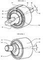
- An elastomeric bearing 10 also referred to as a rubber-metal bearing, which is shown in section and in a three-dimensional view, comprises an outer bearing component 12 with a bearing surface 14 and an inner bearing component 22 having a bearing bore 16 with a bearing surface 24 between which an elastomeric body 26 is clamped allows the inner and outer bearing component.
- the im inner bearing component 22 located bearing bore 16 has a central inner connection axis 28 and located between the outer bearing member 12 and the inner bearing member 22 elastomer body space 30 has a bearing main axis 32, wherein the inner connection axis 28 and the bearing main axis 32 a distance a > 0 and a tilt angle ⁇ > 0 to each other.
- the bearing main axis 32 is the axis of rotation of the outer bearing surface 14.
- straight line 58 is a parallel to the inner connection axis 28, which intersects the main bearing axis 32 at the point of the shortest distance a of the main bearing axis 32 to the inner connection axis 28.
- the surrounding component 42 by a corresponding mechanical processing which is the outer bearing surface 14, at the same time outer bearing member 12.
- the vulcanized on the inner bearing member 22 elastomer body 26 is in this variant in the outer bearing member 12th pressed.
- the inner bearing surface 24 has elevations for setting a special spring property of the elastomer body 26.
- the end surface radii I 44 and II 46 mounted on the outer bearing component 12 and lying within the elastomer body space 30 are different.
- the elastomer body 26 has at the end faces areas 48, 50 which are outside of the elastomer body space.
- FIG. 2 a variant of the invention is shown, which has for attachment of the inner bearing member 22 to a further axle member bearing plates 20. Furthermore, this bearing contains the modification of the bearing property serving kidneys 52 and for the same reason an intermediate sleeve 54.
- this invention variant of the bearing is designed slotted. The surfaces of the slot 56 are in this variant of the invention in the assembled state to each other.
- FIG. 3 a variant of the invention is shown, which has a bearing pin 24 for connecting the inner bearing component 22 to a further axle component.
- the elastomeric body 26 may be embodied in various variants corresponding to the prior art. For example, it may contain recesses called kidneys, which may continue to have internal attacks. In the elastomer body 26 may be inserted metal or plastic parts. The elastomeric body may be slit. The elastomeric body can be used as a so-called hydraulic bearing with enclosed fluid to achieve special damping values of the bearing. The elastomeric body may further comprise a sliding surface on the outer bearing surface 14 or on the inner bearing surface 24. If no sliding surface is desired, the attachment of the elastomeric body 26 to the inner bearing component 22 and / or to the outer bearing component 12 may be performed by vulcanization, by gluing, by interference fit and in a similar manner known per se.
Description
Die Erfindung betrifft ein Elastomerlager gemäß dem Oberbegriff des Patentanspruches 1.The invention relates to an elastomer bearing according to the preamble of
Solche vorzugsweise im Kraftfahrzeugbau eingesetzten, als Stossdämpfer, Achsführungselemente sowie auch als Gummimetalllager verwendeten Elastomerlager sind vielfach bekannt. Sie dienen bei der schwenkbaren Lagerung von Radführungsgliedern der gleichzeitigen Abfederung und Dämpfung von störenden Laststößen und zur gleichzeitigen Verminderung von Fahrgeräuschen. Die Federeigenschaft der Elastomerlager wird bei Achsen in Fahrzeugen auch gezielt dazu verwendet, die Achskinematik und somit die Radstellung, das heißt Spur, Sturz, Längs-, Quer- und Vertikalverschiebung, passiv in Abhängigkeit der unterschiedlichen und zeitlich variierenden auf das Rad und die Achse einwirkenden Kräfte zu bringen. Dazu werden besondere und üblicherweise gleichzeitig unterschiedliche und nicht immer zu vereinbarende Anforderungen an die Feder- und Dämpfeigenschaften des Elastomerlagers in die jeweils drei translatorischen und jeweils drei rotatorischen Raumrichtungen gestellt.Such preferably used in motor vehicle, as shock absorbers, axle guide elements and also used as rubber-metal bearings elastomer bearings are widely known. They serve in the pivotable mounting of Radführungsgliedern the simultaneous cushioning and damping of disturbing load surges and the simultaneous reduction of driving noise. The spring characteristic of the elastomeric bearings is also used specifically for axles in vehicles, the axle kinematics and thus the wheel position, that is track, camber, longitudinal, lateral and vertical displacement, passive depending on the different and time-varying acting on the wheel and the axle To bring forces. For this purpose, special and usually simultaneously different and not always to be agreed upon requirements for the spring and damping properties of the elastomer bearing in the three translational and three rotational spatial directions.
Das gattungsbildende, als Drehgleitlager für die Stützachsen des Fahrwerks eines Kraftfahrzeuges ausgebildete Elastomerlager gemäß der
Eine solche Ausbildung hat aber, wie die Erfahrung gezeigt hat, den Nachteil, dass die Axialsteifigkeit des Elastomerkörpers undefiniert wird. Dies ist bei einer elastokinematischen Fahrwerkauslegung für Achslenker unerwünscht, da oft eine hohe Steifigkeit in Lenkerrichtung, das bedeutet zwischen einem karosserieseitigen und einem radseitigen Kinematikpunkt, angestrebt wird, wobei die torsionale und kardanische Steifigkeit der Lager möglichst gering sein soll. Wird berücksichtigt, dass konventionelle Elastomerlager tendenziell in radialer Richtung deutlich steifer sind als in axialer Richtung und das die torsionale Steifigkeit in der Regel deutlich geringer ist als die kardanische, so liegt nahe, dass in der Regel versucht wird, die Lager so auszurichten, dass die Hauptbeanspruchungen und - belastungen translatorisch in radialer Richtung und rotatorisch in torsionaler Richtung liegen.However, such training has, as experience has shown, the disadvantage that the axial stiffness of the elastomer body is undefined. This is undesirable in a elastokinematische suspension design for wishbone, since often a high rigidity in the direction of the handlebar, that is between a body-side and a wheel-side kinematic point, is sought, the torsional and gimbal stiffness of the bearing should be as low as possible. It is considered that conventional elastomeric bearings tend to be much stiffer in the radial direction than in the axial direction Direction and the torsional stiffness is usually much lower than the gimbal, so it is obvious that it is usually tried to align the bearings so that the main stresses and - loads are translationally in the radial direction and rotational in the torsional direction.
Die bekannten Elastomerlager können aber, wie die Erfahrung gezeigt hat, wegen äußerer Zwänge nicht immer in einer optimalen Ausrichtung in Radträger, Achslenker, Aggregateträger und weitere Bauteile eines Fahrwerks eingebaut werden.However, as experience has shown, the known elastomeric bearings can not always be installed in an optimal orientation in wheel carriers, axle links, subframes and other components of a chassis due to external constraints.
Hier Abhilfe durch ein neues Elastomerlager unter Anwendung der nicht koaxialen Ausrichtung von Drehlager des Elastomerlagers und der Lagerbohrung seines inneren Lagerbauteils zu schaffen ist Aufgabe der Erfindung.This remedy by creating a new elastomeric bearing using the non-coaxial alignment of pivot bearing of the elastomeric bearing and the bearing bore of its inner bearing component is the object of the invention.
Ausgehend von einem Elastomerlager der eingangs genannten Art ist diese Aufgabe erfindungsgemäß durch die kennzeichnenden Merkmale des Patentanspruches 1 gelöst.Starting from an elastomeric bearing of the type mentioned above, this object is achieved by the characterizing features of
Weitere Merkmale der Erfindung ergeben sich aus den Unteransprüchen.Further features of the invention will become apparent from the dependent claims.
Gemäß der Erfindung ist also zusätzlich zur Lagerhauptachse, um die der den Elastomerkörper aufnehmende Elastomerkörperraum konstruiert ist und welche die Axialrichtung des Lagers vorgibt, dem Lagerkern eine weitere, sogenannte innere Anbindungsachse definiert zugeordnet, an der die Funktionsflächen des Lagerkerns, die der Anbindung des Lagers an weiter Bauteile dienen, ausgebildet sind, sodass eine durch den Elastomerkörper definierte Axialsteifigkeit erzielbar ist.According to the invention, therefore, in addition to the bearing main axis, around which the elastomeric body receiving elastomer body space is constructed and which defines the axial direction of the bearing, the bearing core another, so-called inner connection axis defined assigned to the functional surfaces of the bearing core, the connection of the bearing continue to serve components are formed so that a defined by the elastomer body axial rigidity can be achieved.
Die Lagerhauptachse und die innere Anbindungsachse lassen sich in einem dem Elastomerlager zugeordneten, dreidimensionalen Koordinatensystem vektoriell beschreiben und zeichnen sich durch den Verkantwinkel α > 0 und den Abstand a > 0 aus.The main bearing axis and the inner connection axis can be vectorially described in a three-dimensional coordinate system assigned to the elastomer bearing and are characterized by the tilt angle α> 0 and the distance a > 0 .
Der Elastomerkörperraum des erfindungsgemäßen Lagers gleicht in der Gestaltung demjenigen konventioneller, dem Stand der Technik entsprechender Lager, wobei als Elastomerkörperraum bei einem solchen Lager der Raum bezeichnet wird, der durch die am äußeren Lagerbauteil anliegende äußere Lagerfläche und die am inneren Lagerbauteil anliegende innere Lagerfläche begrenzt wird und dem Elastomerkörper beim unbelasteten Lager in diesem Bereich zur Verfügung steht. Bei der Lagerhauptachse handelt es sich daher in der Regel um die Rotationsachse der in der Regel als Rotationsfläche ausgebildeten äußeren Lagerfläche bzw. um eine Parallele zu dieser. Zur Modifikation der Lagereigenschaften kann die Rotationsfläche Aussparungen oder Ausbuchtungen, und/oder unterschiedliche Radien und Fasen im Randbereich haben. Bei wesentlichen Bestandteilen der äußeren Lagerfläche kann es sich aber auch um Extrusions- oder Kegelflächen handeln, deren Konstruktionsachse die Lagerhauptachse oder eine Parallele dazu ist.The elastomeric body space of the bearing according to the invention is similar in design to that of conventional prior art bearings, the elastomeric body space in such a bearing being the space bounded by the outer bearing component bearing outer bearing surface and the inner bearing component bearing inner bearing surface and the elastomeric body is available at the unloaded warehouse in this area. The main bearing axis is therefore generally the axis of rotation of the outer bearing surface, which is generally designed as a surface of revolution, or a parallel to it. In order to modify the bearing properties, the surface of revolution may have recesses or bulges, and / or different radii and chamfers in the edge region. However, essential components of the outer bearing surface may also be extrusion or conical surfaces whose structural axis is the bearing main axis or a parallel thereto.
Weitere geometrische Ausführungen des Elastomerkörperraums, die sich eindeutig und logisch sinnvoll auf die Lagerhauptachse beziehen sind denkbar.Other geometrical embodiments of the elastomer body space, which relate clearly and logically meaningful to the main bearing axis are conceivable.
Bei den an der inneren Anbindungsachse ausgerichteten Funktionsflächen zur Anbindung des Lagers an weitere Bauteile handelt es sich um eine Lagerkernbohrung, ein oder zwei Lagerkernlaschen oder ein oder zwei Lagerkernzapfen.The functional surfaces aligned on the inner connection axis for connecting the bearing to other components are a bearing core bore, one or two bearing core lugs or one or two bearing core pegs.
Durch die erfindungsgemäße Ausbildung des Elastomerlagers mit nicht koaxialer Ausrichtung von Lagerhauptachse und innerer Anbindungsachse, die eine aus vorgegebenen Konstruktionsdaten vorbestimmte Lage im definierten Konstruktionsraum einnehmen, kann das Elastomerlager der erfindungsgemäßen Art eine optimale Funktionsausrichtung für den vorgegebenen Anwendungszweck erhalten, unter Berücksichtigung von funktions-, montage-, festigkeits- und fertigungstechnischen Notwendigkeiten. Das Lager kann auf diese Weise zum Beispiel so ausgerichtet werden, dass es nur minimale Kräfte in Richtung der Lagerhauptachse übertragen muß.Due to the inventive design of the elastomeric bearing with non-coaxial alignment of the bearing main axis and inner connection axis, which assume a predetermined design data predetermined location in the defined design space, the elastomeric bearing of the type according to the invention can obtain an optimal functional alignment for the given application, taking into account functional, assembly -, strength and manufacturing needs. The bearing can be aligned in this way, for example, so that it must transmit only minimal forces in the direction of the bearing main axis.
Die Erfindung ist nachfolgend anhand von einem im Schnitt und in räumlicher Ansicht und zwei nur in räumlicher Ansicht dargestellten Ausführungsbeispielen beschrieben.The invention is described below with reference to an embodiment shown in section and in three-dimensional view and two only in a three-dimensional view.
Ein in
Die in
Bei der in
In
In
Zwecks Modifikation der Lagereigenschaften des Elastomerlagers 10, kann der Elastomerkörper 26 in verschiedenen, dem Stand der Technik entsprechenden Varianten ausgeführt sein. So kann er zum Beispiel als Nieren bezeichnete Aussparungen beinhalten, die weiterhin innere Anschläge haben können. In den Elastomerkörper 26 können Metall- oder Kunststoffteile eingelegt sein. Der Elastomerkörper kann geschlitzt sein. Der Elastomerkörper kann als sogenanntes Hydrolager mit eingeschlossenem Fluid dargestellt sein, um spezielle Dämpfungswerte des Lagers zu erzielen. Der Elastomerkörper kann weiterhin an der äußeren Lagerfläche 14 oder an der inneren Lagerfläche 24 eine Gleitfläche aufweisen. Falls keine Gleitfläche gewünscht ist, kann die Befestigung des Elastomerkörpers 26 an das innere Lagerbauteil 22 und/oder an das äußere Lagerbauteil 12 durch Vulkanisierung, durch Klebung, durch Presspassung und in ähnlicher, an sich bekannter Weise ausgeführt sein.In order to modify the bearing properties of the elastomeric bearing 10, the
- 1010
- Elastomerlagerelastomeric bearings
- 1212
- äußeres Lagerbauteilouter bearing component
- 1414
- äußere Lagerflächeouter storage area
- 1616
- Lagerbohrungbearing bore
- 1818
- Lagerzapfenpivot
- 2020
- Lagerlaschenbearing plates
- 2222
- inneres Lagerbauteilinner bearing component
- 2424
- innere Lagerflächeinner storage area
- 2626
- Elastomerkörperelastomer body
- 2828
- innere Anbindungsachseinner connection axis
- 3030
- ElastomerkörperraumElastomer body space
- 30a,b,c,d30a, b, c, d
- Grenzen des ElastomerkörperraumLimits of the elastomer body space
- 3232
- LagerhauptachseBearings main axis
- 3838
- AchslenkerrichtungAchslenkerrichtung
- 4242
- Umgebungsbauteilenvironment component
- 4444
- Stirnflächenradius IFace radius I
- 4646
- Stirnflächenradius IIFace radius II
- 4848
- außen liegender Elastomerkörperbereichouter elastomeric body area
- 5050
- außen liegender Elastomerkörperbereichouter elastomeric body area
- 5252
- Nierekidney
- 5454
- Zwischenhülseintermediate sleeve
- 5656
- Längsschlitzlongitudinal slot
- 5858
- Parallele zur AnbindungsachseParallel to the connection axis
Claims (4)
- Elastomeric bearing (10) with an elastomeric body (26) arranged between an outer and an inner bearing component (12, 22) and facilitating elastic movements between the bearing components, which is mounted between the facing bearing surfaces (14, 24) of the bearing components (12, 22) and whose axis (32) serving as the main bearing axis encloses an angle with the axis (28) of the bearing bore (16) of the inner bearing component, characterised in that for the purposes of the functional alignment of the elastomeric bearing (10) with respect to the forces acting in the axial direction (38), whose bearing bore (16), with its axis (28) serving as an inner connection axis forms a functional surface aligned thereto and serving to join the elastomeric bearing (10) to further components, independently of the axis (28) of the inner bearing component (22) the main bearing axis (32) aligned to the bearing surface (14) of the outer bearing component (12) has a cant angle of α > 0 and a distance of a > 0 to the axis (28) of the inner bearing component (22).
- Elastomeric bearing according to claim 1, characterised in that the functional surface aligned with the inner connection axis (28) and serving to join the elastomeric bearing (10) to further components is made as a bearing journal (18) or as one or two bearing lugs 20.
- Elastomeric bearing according to claims 1 and 2, characterised in that the bearing component (12) that has the outer bearing surface (14) is made as a functional surface (42) aligned to the inner connection axis (28), which contains an axle guide, a wheel carrier, a pendulum support, a unit carrier or a similar functional component.
- Elastomeric bearing according to claims 1 to 3, characterised in that the elastomeric body (26) contains fluid filled cavities serving to modify the bearing characteristics and an associated duct system.
Applications Claiming Priority (2)
| Application Number | Priority Date | Filing Date | Title |
|---|---|---|---|
| DE200410013554 DE102004013554A1 (en) | 2004-03-19 | 2004-03-19 | elastomeric bearings |
| DE102004013554 | 2004-03-19 |
Publications (2)
| Publication Number | Publication Date |
|---|---|
| EP1577126A1 EP1577126A1 (en) | 2005-09-21 |
| EP1577126B1 true EP1577126B1 (en) | 2008-09-03 |
Family
ID=34833198
Family Applications (1)
| Application Number | Title | Priority Date | Filing Date |
|---|---|---|---|
| EP20050001157 Expired - Fee Related EP1577126B1 (en) | 2004-03-19 | 2005-01-21 | Elastomeric mounting |
Country Status (2)
| Country | Link |
|---|---|
| EP (1) | EP1577126B1 (en) |
| DE (2) | DE102004013554A1 (en) |
Cited By (1)
| Publication number | Priority date | Publication date | Assignee | Title |
|---|---|---|---|---|
| DE102008044060B4 (en) * | 2008-11-25 | 2012-02-23 | Saf-Holland Gmbh | Brake system for disc brakes |
Families Citing this family (7)
| Publication number | Priority date | Publication date | Assignee | Title |
|---|---|---|---|---|
| ITTO20060877A1 (en) * | 2006-12-11 | 2008-06-12 | Fiat Auto Spa | ARTICULATING DEVICE, PARTICULARLY FOR AN ARM OF A SUSPENSION OF A MOTOR VEHICLE |
| DE102012200251B4 (en) * | 2012-01-10 | 2022-03-17 | Zf Friedrichshafen Ag | Handlebar with elastomer component |
| DE102013011589A1 (en) * | 2013-07-11 | 2015-01-15 | Audi Ag | Suspension link for a vehicle and method for producing a suspension link |
| DE102017206342B4 (en) | 2017-04-12 | 2023-04-27 | Ford Global Technologies, Llc | Wheel control arm for a wheel suspension of a vehicle |
| JP6975030B2 (en) * | 2017-12-05 | 2021-12-01 | 倉敷化工株式会社 | Anti-vibration device and anti-vibration structure |
| EP3872361A1 (en) * | 2020-02-26 | 2021-09-01 | Volvo Car Corporation | Bushing |
| IT202200002969A1 (en) * | 2022-02-17 | 2023-08-17 | Ferrari Spa | SUSPENSION EQUIPPED WITH BUSHING WITH INCLINED FIXING AXIS AND RELEVANT ROAD VEHICLE |
Family Cites Families (8)
| Publication number | Priority date | Publication date | Assignee | Title |
|---|---|---|---|---|
| DE7141159U (en) * | 1971-10-30 | 1972-07-20 | Boge Gmbh | Elastic bearing, in particular for axle fastenings and axle guide elements on motor vehicles |
| DE2838391C2 (en) * | 1978-09-02 | 1984-10-04 | Volkswagenwerk Ag, 3180 Wolfsburg | Rubber-to-metal bearings for the storage of a wheel guide member |
| DE3613123A1 (en) * | 1986-04-18 | 1987-10-29 | Lemfoerder Metallwaren Ag | Elastic pivot-slide bearing for chassis parts in motor vehicles |
| DE3724431A1 (en) * | 1987-07-23 | 1989-02-02 | Freudenberg Carl Fa | SLEEVE RUBBER SPRING |
| FR2683773A1 (en) * | 1991-11-15 | 1993-05-21 | Hutchinson | ELASTIC COMPENSATING BILGE FOR THE CONNECTION BETWEEN THE REAR SUSPENSION TRAIN AND THE BODY OF A VEHICLE. |
| DE4139582C1 (en) * | 1991-11-30 | 1992-11-12 | Bayerische Motoren Werke Ag, 8000 Muenchen, De | Rubber bearing suitable for car bodywork components - has layer of elastic material between outer and inner parts with ribs facing each other |
| DE10157712A1 (en) * | 2001-11-24 | 2003-06-05 | Daimler Chrysler Ag | Leaf spring rear suspension for vehicles |
| DE20202241U1 (en) * | 2002-02-14 | 2002-06-13 | Trw Fahrwerksyst Gmbh & Co | elastomer joint |
-
2004
- 2004-03-19 DE DE200410013554 patent/DE102004013554A1/en not_active Withdrawn
-
2005
- 2005-01-21 DE DE200550005229 patent/DE502005005229D1/en active Active
- 2005-01-21 EP EP20050001157 patent/EP1577126B1/en not_active Expired - Fee Related
Cited By (2)
| Publication number | Priority date | Publication date | Assignee | Title |
|---|---|---|---|---|
| DE102008044060B4 (en) * | 2008-11-25 | 2012-02-23 | Saf-Holland Gmbh | Brake system for disc brakes |
| DE102008044060C5 (en) * | 2008-11-25 | 2016-10-06 | Saf-Holland Gmbh | Brake system for disc brakes |
Also Published As
| Publication number | Publication date |
|---|---|
| DE502005005229D1 (en) | 2008-10-16 |
| EP1577126A1 (en) | 2005-09-21 |
| DE102004013554A1 (en) | 2005-10-13 |
Similar Documents
| Publication | Publication Date | Title |
|---|---|---|
| EP1577126B1 (en) | Elastomeric mounting | |
| DE2841505C2 (en) | Hydraulically damping rubber mount | |
| EP1985475B1 (en) | Supported suspension unit bearing for wheel suspensions | |
| DE102012200001A1 (en) | Rubber-metal bearing for trapezoidal-link in wheel suspension, has rubber elastic body fastened and arranged between outer bush and inner bush, where outer bush has front end surface at which leading elastic damping element is mounted | |
| EP2607739B1 (en) | Elastic joint, particularly for a wheel suspension of a motor vehicle | |
| EP2604453B1 (en) | Transverse leaf spring with a rigidly connected elastic body for a vehicle | |
| DE102009004175A1 (en) | Passive stabilizer device for a vehicle wheel suspension and suspension | |
| DE3507432A1 (en) | SUSPENSION FOR A DRIVE AXLE OF A MOTOR VEHICLE | |
| DE102005001742A1 (en) | Shock absorbing strut, has spring carrier connected over bearing at component which is to be supported, where bearing has spherical support surfaces which permit pivoting of strut for supporting component | |
| DE20313665U1 (en) | System for rolling angle reduction in motor vehicles | |
| EP1720722A2 (en) | Wheel-guiding joint | |
| DE102008044103A1 (en) | Wheel suspension for guidable vehicle wheel, particularly commercial vehicle, has wheel head with knuckle and two knuckle pins arranged coaxially to rotational axis of knuckle in sections | |
| DE19580267B4 (en) | Arrangement for suspending a suspension vehicle cab on a vehicle frame | |
| DE3119361C2 (en) | Joint between a push strut of a wheel suspension of a motor vehicle and a connection fitting on the vehicle | |
| WO2010069303A1 (en) | Twist-beam rear axle for a vehicle | |
| DE10205264A1 (en) | Suspension strut | |
| DE102013225978A1 (en) | Actuator for an active roll stabilizer and roll stabilizer | |
| EP3384178B1 (en) | Hydraulic bearing bushing | |
| DE102011085557A1 (en) | Suspension strut bearing for wheel suspension system of motor vehicle, has thrust and radial bearings arranged between cap and guide ring, and snap connection arranged between radial and thrust bearings | |
| DE102012221841B4 (en) | Rubber-metal bearings for automotive suspension, trapezoidal link and suspension | |
| DE4008465A1 (en) | Preloaded automotive suspension bearing - has recesses in elastomer body opposite each other in transverse direction | |
| DE102006026961A1 (en) | Composite pivot pin for motor vehicle, comprises front ends of longitudinal guide are connected firmly with axle body, and wheel is positioned at rear ends of longitudinal guide | |
| WO2014161702A1 (en) | Axle guide bearing for coupling a rear axle to a body of a motor vehicle | |
| EP1535766B1 (en) | Motor vehicle wheel suspension | |
| DE202015101117U1 (en) | Independent and rear suspension with independent wheel suspensions for one vehicle |
Legal Events
| Date | Code | Title | Description |
|---|---|---|---|
| PUAI | Public reference made under article 153(3) epc to a published international application that has entered the european phase |
Free format text: ORIGINAL CODE: 0009012 |
|
| AK | Designated contracting states |
Kind code of ref document: A1 Designated state(s): AT BE BG CH CY CZ DE DK EE ES FI FR GB GR HU IE IS IT LI LT LU MC NL PL PT RO SE SI SK TR |
|
| AX | Request for extension of the european patent |
Extension state: AL BA HR LV MK YU |
|
| 17P | Request for examination filed |
Effective date: 20060321 |
|
| AKX | Designation fees paid |
Designated state(s): DE FR GB IT |
|
| 17Q | First examination report despatched |
Effective date: 20070620 |
|
| GRAP | Despatch of communication of intention to grant a patent |
Free format text: ORIGINAL CODE: EPIDOSNIGR1 |
|
| GRAS | Grant fee paid |
Free format text: ORIGINAL CODE: EPIDOSNIGR3 |
|
| GRAA | (expected) grant |
Free format text: ORIGINAL CODE: 0009210 |
|
| AK | Designated contracting states |
Kind code of ref document: B1 Designated state(s): DE FR GB IT |
|
| REG | Reference to a national code |
Ref country code: GB Ref legal event code: FG4D Free format text: NOT ENGLISH |
|
| REF | Corresponds to: |
Ref document number: 502005005229 Country of ref document: DE Date of ref document: 20081016 Kind code of ref document: P |
|
| PLBE | No opposition filed within time limit |
Free format text: ORIGINAL CODE: 0009261 |
|
| STAA | Information on the status of an ep patent application or granted ep patent |
Free format text: STATUS: NO OPPOSITION FILED WITHIN TIME LIMIT |
|
| 26N | No opposition filed |
Effective date: 20090604 |
|
| REG | Reference to a national code |
Ref country code: DE Ref legal event code: R084 Ref document number: 502005005229 Country of ref document: DE Effective date: 20130117 |
|
| REG | Reference to a national code |
Ref country code: FR Ref legal event code: PLFP Year of fee payment: 12 |
|
| PGFP | Annual fee paid to national office [announced via postgrant information from national office to epo] |
Ref country code: DE Payment date: 20160131 Year of fee payment: 12 Ref country code: IT Payment date: 20160129 Year of fee payment: 12 |
|
| PGFP | Annual fee paid to national office [announced via postgrant information from national office to epo] |
Ref country code: FR Payment date: 20160128 Year of fee payment: 12 Ref country code: GB Payment date: 20160127 Year of fee payment: 12 |
|
| REG | Reference to a national code |
Ref country code: DE Ref legal event code: R119 Ref document number: 502005005229 Country of ref document: DE |
|
| GBPC | Gb: european patent ceased through non-payment of renewal fee |
Effective date: 20170121 |
|
| REG | Reference to a national code |
Ref country code: FR Ref legal event code: ST Effective date: 20170929 |
|
| PG25 | Lapsed in a contracting state [announced via postgrant information from national office to epo] |
Ref country code: FR Free format text: LAPSE BECAUSE OF NON-PAYMENT OF DUE FEES Effective date: 20170131 |
|
| PG25 | Lapsed in a contracting state [announced via postgrant information from national office to epo] |
Ref country code: GB Free format text: LAPSE BECAUSE OF NON-PAYMENT OF DUE FEES Effective date: 20170121 Ref country code: DE Free format text: LAPSE BECAUSE OF NON-PAYMENT OF DUE FEES Effective date: 20170801 |
|
| PG25 | Lapsed in a contracting state [announced via postgrant information from national office to epo] |
Ref country code: IT Free format text: LAPSE BECAUSE OF NON-PAYMENT OF DUE FEES Effective date: 20170121 |