EP1577031A1 - Verfahren und Vorrichtung zur Herstellung von Rahmen - Google Patents
Verfahren und Vorrichtung zur Herstellung von Rahmen Download PDFInfo
- Publication number
- EP1577031A1 EP1577031A1 EP05102107A EP05102107A EP1577031A1 EP 1577031 A1 EP1577031 A1 EP 1577031A1 EP 05102107 A EP05102107 A EP 05102107A EP 05102107 A EP05102107 A EP 05102107A EP 1577031 A1 EP1577031 A1 EP 1577031A1
- Authority
- EP
- European Patent Office
- Prior art keywords
- profiles
- corner connector
- connector unit
- adjacent
- arm
- Prior art date
- Legal status (The legal status is an assumption and is not a legal conclusion. Google has not performed a legal analysis and makes no representation as to the accuracy of the status listed.)
- Granted
Links
- 238000000034 method Methods 0.000 title claims description 11
- 238000004519 manufacturing process Methods 0.000 title claims description 7
- 238000004080 punching Methods 0.000 claims description 6
- 238000004049 embossing Methods 0.000 claims description 5
- 230000005540 biological transmission Effects 0.000 claims description 3
- 230000002093 peripheral effect Effects 0.000 claims description 2
- 150000001875 compounds Chemical class 0.000 description 1
- 230000008602 contraction Effects 0.000 description 1
- 238000005520 cutting process Methods 0.000 description 1
- 238000006073 displacement reaction Methods 0.000 description 1
- 230000009347 mechanical transmission Effects 0.000 description 1
- 238000003825 pressing Methods 0.000 description 1
Images




Classifications
-
- B—PERFORMING OPERATIONS; TRANSPORTING
- B21—MECHANICAL METAL-WORKING WITHOUT ESSENTIALLY REMOVING MATERIAL; PUNCHING METAL
- B21D—WORKING OR PROCESSING OF SHEET METAL OR METAL TUBES, RODS OR PROFILES WITHOUT ESSENTIALLY REMOVING MATERIAL; PUNCHING METAL
- B21D53/00—Making other particular articles
- B21D53/74—Making other particular articles frames for openings, e.g. for windows, doors, handbags
- B21D53/745—Joining mitred profiles comprising punching the profiles on a corner-angle connecting piece
Definitions
- the present invention relates to a method and an apparatus for production of frames, in particular for windows or doors, with a plurality of corner connector units, into each of the two profiles in the miter area abutting each corner connector unit is means for aligning and means for fixing having the profiles.
- the Eckverbinderüen simultaneously relative to each other moves until the respective adjacent profiles form fit to the respective Corner connector unit abut with a certain contact pressure. Only then will be the respective adjacent profiles together to form a circumferential Frame set.
- the simultaneous movement of the corner connector units it is achieved that deviations do not sum in a corner of the frame but the deviations are distributed according to the individual corners become. It is almost accepted that by deviations the Angle between the individual profiles may differ slightly, but in the Miter area for a positive-locking system is present and no Can form a column. As a result, tolerance-related deviations are distributed evenly across all corner areas of the frame and it will not try despite existing deviations, the frame profiles exactly according to one Align target value.
- the contact pressure on all Eckverbinderüen held to pre-fixing the profiles about the same size to tolerances Distribute displacements of the profiles to all corner areas.
- the corner connector units to compensate for tolerances of Profiles when moving to the adjacent profiles about an axis perpendicular to the two longitudinal axes of the profiles pivoted so that a fix deviating is possible from a predetermined target angle. Because the deviations in the practice are anyway only in a range of, for example, less than 1 ° fall these deviations optically not on.
- each corner connector unit In the device according to the invention are means for aligning the profiles provided by means of each corner connector unit relative to the other Eckverbinderüen movable and with a certain contact pressure to two adjacent Profiles can be applied. This is how the orientation of the profiles can be achieved tolerance deviations are distributed to all corners.
- a common drive for aligning and tensioning the profiles intended.
- the drive can be via mechanical transmission means, for example a circulating cable, hydraulic transmission means or the like feature. It is also possible to provide electrical drives on each arm, where a predetermined contact pressure is set.
- each corner connector unit is mounted on a pivotable arm. Further, each corner connector unit on the arm about an axis perpendicular to the Longitudinal axis of adjacent profiles to be rotatably mounted, so then a corresponding Pivoting is also possible when aligning the profiles.
- each corner connector unit has an outer receptacle for inserting two adjacent profiles in the miter area and in the interior Area a relative thereto movable abutment. For the final fixation are then punched or stamped on each corner connector unit for deformation and fixing the walls of the respective profile provided.
- a Eckverbinderkaschine 1 is used to produce a frame 2, which consists of four Profiles 3, 4, 5, 6 is formed, which may have an identical cross-section.
- the profiles 3, 4, 5, 6 are each mitred, with the miter surface at an angle of 45 ° to the longitudinal axis of the profiles 3, 4, 5, 6 is arranged.
- the profiles 3, 4, 5, 6 are each in the range of miter surfaces on Eckverbinderäen 11, 12, 13 and 14, wherein two adjacent profiles 3 and 4 at the corner connector unit 11, the profiles 4 and 5 on the corner connector unit 12, etc. are held.
- Each corner connector unit 11, 12, 13 and 14 is on a support arm 7, 8, 9 or 10 arranged movable.
- Each support arm is 7, 8, 9 and 10 pivotable about a common axis 15, the arms 7, 8, 9 and 10 respectively can be pivoted independently.
- the corner connector units 11, 12, 13 and 14 have a schematically illustrated Force mechanism 16, 17, 18 and 19, by means of the two adjacent profiles. 3 up to 6 can be included in the area of the miter area and inside pressed perpendicular to the miter surface. Each force mechanism 16, 17, 18 and 19 brings about the same inward force to the Profiles in the corner areas optimally to each other and then together connect to.
- the Eckverbinderkaschine 1 of Figure 1 is shown, wherein the force mechanism mechanically modified for the corner connector units 11, 12, 13 and 14 is shown.
- a tensioning cable 20 is provided which is of a schematically shown drive 21st stretched and guided around a first guide roller 22. Then the rope is led to corresponding guides on the corner connectors 12, 11, 14 and 13, before it extends to a deflection roller 23 and an end point 24.
- the Eckverbinderüen 11 to 14 evenly driven inwards on the corners, whereby the contact pressure due to the tensioning of the rope 20 evenly on the individual corner areas distributed.
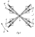
- the Eckverbinderkaschine 1 is shown schematically without profiles 3 to 6.
- the Eckverbinderkaschine 1 includes arms 7, 8, 9 and 10, which is a common Rotary axis 15 are pivotable.
- Each arm 7 to 10 is however for itself taken according to the arrow 25 pivoted so that each corner of a Frame profile can be slightly offset, as indicated by the dashed Arms 7 ', 8', 9 'and 10' is shown.
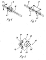
- an arm 10 of the Eckverbinderkaschine 1 is shown enlarged.
- a corner connector unit 14 along the longitudinal axis of the arm 10th slidably mounted and can via a power mechanism, not shown to be pushed inwards.
- the corner connector unit 14 is also on the arm 10 rotatably mounted, as indicated schematically by the arrow 26. hereby
- the corner connector 14 may be self-aligning through the two profiles be sure that on two adjacent profiles one substantially equal force by pressing the corner connector unit 14 is exercised.
- the arm 10 is shown with the corner connector unit 14, wherein the Corner connector 14 can be moved inwardly to the position 14 'as it indicated by the arrow 27. This allows the arm 10 and the Corner connector unit 14 are adapted to different frame sizes.
- the corner connector unit 14 is shown enlarged.
- a receptacle 31 is provided, which together with the corner connector unit 14 about an axis 32 relative to the arm 10 of the Eckverbinderkaschine 1, such as shown in Fig. 4 is pivotable.
- the receptacle 31 is by means of a carriage slidably mounted on the arm 10 in its longitudinal direction.
- the recording 31 is formed bolt-shaped and includes an angular recess 38, the in this embodiment is formed approximately at right angles and two mitred cut profiles on the outer area can accommodate.
- the outer frame corner is approximately on the axis 32nd
- two punching and embossing blades 30 are provided, which are movable substantially perpendicular to the miter plane 39.
- By the punching and embossing blades 30 can emboss the walls of the profiles 3 to 6 or be punched, as already shown in DE 197 00 604.
- corner connector unit 14 includes a abutment 28, which is removed from a Position 28 'in an abutment position 28 is movable, as with the Arrow 29 is indicated.
- Eckverbinderkaschine 1 shown in Figure 7 is instead of a square Frame 2 made a rectangular frame.
- the arms 7, 8, 9 and 10 arranged at a modified angle, with a corresponding rotation has taken place about the axis 15.
- By the rotation of the corner connector units 11, 12, 13 and 14 about the respective axes of rotation takes place an alignment such that adjacent profiles again through the corner connector units 11, 12, 13 and 14th aligned and fixed to each other.
- the arms 41 and 42 are mounted on a common holder 43, wherein the Arm 41 is rotatable about the rotation axis 44 and the arm 42 about the rotation axis 45.
- the holder 43 is slidably mounted on a bar 40.
- On the opposite Side is a mirror image arranged holder provided with two arms.
- On each arm 41 and 42 is respectively a corner connector unit 12 and 13 and 11 and 14 arranged as described in the previous embodiment is.
- the corner connector unit 11 to 14 is associated with a drive, the fixed by means of a predetermined contact pressure profiles 3 to 6, and then then connect to a frame.
- the invention is not limited to the illustrated embodiments.
- the embodiments shown are all Eckverbinderritten 11 to 14th movably mounted on an arm 7 to 10 slidably. It is also possible to have one Corner connector to arrange rigid and then all other Eckverbinderritten to move relative to this corner connector unit, whereby it must be ensured that when prefixing the profiles 3 to 6 in about all corners of the same contact pressure existing, thus existing differences in the length of the profiles evenly can be balanced on all corners distributed.
- corner connector units 11 to 14 may be mechanical or be provided hydraulic transmission means, which have a common Drive can be controlled, or it can be provided individual drives, the However, ensure a uniform contact pressure.
Landscapes
- Engineering & Computer Science (AREA)
- Mechanical Engineering (AREA)
- Automatic Assembly (AREA)
- Manufacturing Of Electrical Connectors (AREA)
- Automobile Manufacture Line, Endless Track Vehicle, Trailer (AREA)
- Stringed Musical Instruments (AREA)
- Joining Of Corner Units Of Frames Or Wings (AREA)
Abstract
Description
- Figur 1
- eine Draufsicht auf ein Ausführungsbeispiel einer erfindungsgemäßen Vorrichtung zur Herstellung von Rahmen;
- Figur 2
- eine Draufsicht auf die Vorrichtung der Figur 1 mit Antrieb;
- Figur 3
- eine Draufsicht auf die verschwenkbaren Arme der Vorrichtung der Figur 1 ohne Profile;
- Figur 4
- eine vergrößerte Draufsicht auf einen Arm der Vorrichtung der Figur 1;
- Figur 5
- eine vergrößerte Ansicht eines Arms der Vorrichtung der Figur 5;
- Figur 6
- eine Detailansicht einer Eckverbindereinheit der Vorrichtung der Figur 1;
- Figur 7
- eine Draufsicht auf die Eckverbindereinheit der Figur 1 bei der Herstellung eines Rahmens anderer Geometrie, und
- Figur 8
- eine Draufsicht auf ein modifiziertes Ausführungsbeispiel einer erfindungsgemäßen Vorrichtung.
Claims (13)
- Verfahren zur Herstellung von Rahmen, insbesondere für Fenster oder Türen, mit folgenden Schritten:Einlegen von mehreren Profilen (3, 4, 5, 6) in eine Eckverbindermaschine (1) mit je einer Eckverbindereinheit 11, 12, 13, 14) an einem Gehrungsbereich zweier benachbarter Profile (3 bis 6)Gleichzeitiges Bewegen aller Eckverbindereinheiten (11 bis 14) relativ zueinander bis die jeweils benachbarten Profile (3 bis 6) formschlüssig an der jeweiligen Eckverbindereinheit (11 bis 14) mit einem gewissen Anpressdruck anliegen, undFestlegen der jeweils benachbarten Profile (3 bis 6) aneinander zur Ausbildung eines umlaufenden Rahmens (2).
- Verfahren nach Anspruch 1, dadurch gekennzeichnet, dass der Anpressdruck an allen Eckverbindereinheiten (11 bis 14) zur Vorfixierung der Profile (3 bis 6) etwa gleich groß ist.
- Verfahren nach Anspruch 1 oder 2, dadurch gekennzeichnet, dass die Eckverbindereinheiten (11 bis 14) zum Ausgleich von Toleranzen der Profile (3 bis 6) beim Bewegen zu den benachbarten Profilen (3 bis 6) um eine Achse (32) senkrecht zu den beiden Längsachsen der Profile (3 bis 6) verschwenkt werden.
- Verfahren nach einem der Ansprüche 1 bis 3, dadurch gekennzeichnet, dass die Eckverbindereinheiten (11 bis 14) von außen im Wesentlichen in Richtung der Gehrungsfläche auf die Profile (3 bis 6) bewegt werden und anschließend von innen ein Wiederlager (28) von innen an die Profile (3 bis 6) angelegt wird.
- Verfahren nach einem der Ansprüche 1 bis 4, dadurch gekennzeichnet, dass zum Festlegen der jeweils benachbarten Profile (3 bis 6) mindestens eine Stanzung in die Wand eines Profils (3 bis 6) benachbart zur Gehrungsfläche eingebracht wird.
- Vorrichtung zur Herstellung von Rahmen, insbesondere für Fenster oder Türen, mit mehreren Eckverbindereinheiten (11 bis 14), in die jeweils zwei Profile (3 bis 6) im Gehrungsbereich aneinanderlegbar sind, wobei jede Eckverbindereinheit (11 bis 14) Mittel (28, 31) zum Ausrichten und Mittel (30) zum Festlegen der Profile (3 bis 6) aufweist, dadurch gekennzeichnet, dass zum Ausrichten der Profile (3 bis 6) jede Eckverbindereinheit (11 bis 14) relativ zu den anderen Eckverbindereinheiten (11 bis 14) verfahrbar und mit einem gewissen Anpressdruck an zwei benachbarte Profile (3 bis 6) anlegbar ist.
- Vorrichtung nach Anspruch 6, dadurch gekennzeichnet, dass ein gemeinsamer Antrieb (21) zum Ausrichten und Spannen der Profile (3 bis 6) vorgesehen ist.
- Vorrichtung nach Anspruch 7, dadurch gekennzeichnet, dass der Antrieb (21) mechanische, hydraulische oder pneumatische Übertragungsmittel aufweist.
- Vorrichtung nach einem der Ansprüche 6 bis 8, dadurch gekennzeichnet, dass jede Eckverbindereinheit (11 bis 14) an einem verschwenkbaren Arm (7 bis 10) gelagert ist.
- Vorrichtung nach einem der Ansprüche 6 bis 9, dadurch gekennzeichnet, dass jede Eckverbindereinheit (11 bis 14) an einem Arm (7 bis 10) um eine Achse (32) senkrecht zu den Längsachsen benachbarter Profile (3 bis 6) drehbar gelagert ist.
- Vorrichtung nach einem der Ansprüche 6 bis 10, dadurch gekennzeichnet, dass jeder Arm (7 bis 10) um eine gemeinsame Achse (15) drehbar gelagert ist.
- Vorrichtung nach einem der Ansprüche 6 bis 11, dadurch gekennzeichnet, dass jede Eckverbindereinheit (11 bis 14) eine äußere Aufnahme (31) zum Einfügen zweier benachbarter Profile (3 bis 6) im Gehrungsbereich und im inneren Bereich ein relativ dazu verfahrbares Wiederlager (28) aufweist.
- Vorrichtung nach einem der Ansprüche 6 bis 12, dadurch gekennzeichnet, dass jede Eckverbindereinheit (11 bis 14) Stanz- oder Prägestempel (30) zur Verformung und Fixierung der Wände des jeweiligen Profils (3 bis 6) aufweist.
Applications Claiming Priority (2)
| Application Number | Priority Date | Filing Date | Title |
|---|---|---|---|
| DE102004013998 | 2004-03-19 | ||
| DE102004013998A DE102004013998A1 (de) | 2004-03-19 | 2004-03-19 | Verfahren und Vorrichtung zur Herstellung von Rahmen |
Publications (2)
| Publication Number | Publication Date |
|---|---|
| EP1577031A1 true EP1577031A1 (de) | 2005-09-21 |
| EP1577031B1 EP1577031B1 (de) | 2009-05-27 |
Family
ID=34833231
Family Applications (1)
| Application Number | Title | Priority Date | Filing Date |
|---|---|---|---|
| EP05102107A Expired - Lifetime EP1577031B1 (de) | 2004-03-19 | 2005-03-17 | Verfahren und Vorrichtung zur Herstellung von Rahmen |
Country Status (4)
| Country | Link |
|---|---|
| EP (1) | EP1577031B1 (de) |
| AT (1) | ATE432134T1 (de) |
| DE (2) | DE102004013998A1 (de) |
| ES (1) | ES2327749T3 (de) |
Families Citing this family (1)
| Publication number | Priority date | Publication date | Assignee | Title |
|---|---|---|---|---|
| DE202010008917U1 (de) * | 2010-10-28 | 2012-01-30 | SCHÜCO International KG | Rahmenkonstruktion und Einziehwerkzeug |
Citations (4)
| Publication number | Priority date | Publication date | Assignee | Title |
|---|---|---|---|---|
| DE2257904B1 (de) * | 1972-11-25 | 1973-10-31 | Nickel, Hermann, 8700 Wurzburg | Eckverbindungsgeraet fuer metallhohlprofilrahmen |
| DE2429649A1 (de) * | 1973-06-22 | 1975-01-16 | Daniel Colombo | Verfahren zum zusammenbauen von zargen und rahmen aus metall und vorrichtung zur durchfuehrung des verfahrens |
| DE3021503A1 (de) * | 1980-06-07 | 1982-01-07 | NB Bausysteme GmbH, 3000 Hannover | Vorrichtung fuer die verbindungen von profilstaeben zu einem rahmen, insbesondere fuer die herstellung von fenstern |
| DE19700604A1 (de) * | 1997-01-10 | 1998-07-16 | Schueco Int Kg | Eckverbindermaschine |
-
2004
- 2004-03-19 DE DE102004013998A patent/DE102004013998A1/de not_active Withdrawn
-
2005
- 2005-03-17 EP EP05102107A patent/EP1577031B1/de not_active Expired - Lifetime
- 2005-03-17 AT AT05102107T patent/ATE432134T1/de active
- 2005-03-17 ES ES05102107T patent/ES2327749T3/es not_active Expired - Lifetime
- 2005-03-17 DE DE502005007329T patent/DE502005007329D1/de not_active Expired - Lifetime
Patent Citations (4)
| Publication number | Priority date | Publication date | Assignee | Title |
|---|---|---|---|---|
| DE2257904B1 (de) * | 1972-11-25 | 1973-10-31 | Nickel, Hermann, 8700 Wurzburg | Eckverbindungsgeraet fuer metallhohlprofilrahmen |
| DE2429649A1 (de) * | 1973-06-22 | 1975-01-16 | Daniel Colombo | Verfahren zum zusammenbauen von zargen und rahmen aus metall und vorrichtung zur durchfuehrung des verfahrens |
| DE3021503A1 (de) * | 1980-06-07 | 1982-01-07 | NB Bausysteme GmbH, 3000 Hannover | Vorrichtung fuer die verbindungen von profilstaeben zu einem rahmen, insbesondere fuer die herstellung von fenstern |
| DE19700604A1 (de) * | 1997-01-10 | 1998-07-16 | Schueco Int Kg | Eckverbindermaschine |
Also Published As
| Publication number | Publication date |
|---|---|
| DE502005007329D1 (de) | 2009-07-09 |
| ATE432134T1 (de) | 2009-06-15 |
| ES2327749T3 (es) | 2009-11-03 |
| EP1577031B1 (de) | 2009-05-27 |
| DE102004013998A1 (de) | 2005-10-06 |
Similar Documents
| Publication | Publication Date | Title |
|---|---|---|
| AT403350B (de) | Biegemaschine zum herstellen eines abstandhaltenden innenrahmens für eine isolierglasscheibe | |
| DE68907606T2 (de) | Vorrichtung und verfahren zum herstellen eines werkstückes mit ineinandergreifenden oberflächen. | |
| DE2923769C2 (de) | ||
| WO2012034967A1 (de) | Vorrichtung und verfahren zur herstellung von zumindest teilweise geschlossenen hohlprofilen mit drehbaren gesenkhälften und geringer taktzeit | |
| EP2842653B1 (de) | Werkzeug und Verfahren zum Herstellen von Stanzteilen | |
| EP3031547B1 (de) | Verfahren und vorrichtung zum herstellen einer eckverbindung | |
| WO2017108968A1 (de) | Keiltrieb | |
| DE19700604B4 (de) | Eckverbindermaschine | |
| DE102008006864A1 (de) | Verfahren und Vorrichtung zur Lochung eines Werkstücks | |
| EP0885713B1 (de) | Vorrichtung zum gleichzeitigen Verschweissen von mindestens vier auf Gehrung geschnittenen Profilabschnitten | |
| EP2159366A2 (de) | Verfahren und Vorrichtung zum Herstellen eines rechteckigen Abstandhalterrahmens für Isolierglasscheiben | |
| EP1369215A2 (de) | Anlage zur Herstellung von Gipskarton-Lochplatten sowie Verfahren zur Herstellung von Gipskarton-Lochplatten und deren Verlegung | |
| DE102017117025B4 (de) | Gewindeformstation | |
| EP1577031B1 (de) | Verfahren und Vorrichtung zur Herstellung von Rahmen | |
| DE69900609T2 (de) | Wärmedämmender Baublock | |
| DE4431849A1 (de) | Durchsetz-Fügeverfahren und Durchsetz-Fügewerkzeug | |
| EP0115840B1 (de) | Verfahren und Vorrichtung zum Biegen von hohlen Metallprofilen, insbesondere Rahmenprofilen für Fenster und Türen | |
| DE2336233A1 (de) | Verfahren und vorrichtung zur herstellung von metallstangen mit gezahnten kanten | |
| DE4121108C1 (de) | ||
| DE69414395T2 (de) | Verfahren zur bearbeitung von hohlprofilen, zur formung von rahmen und entsprechende rahmen und hohlprofile | |
| DE19906758A1 (de) | Fenster- und Türflügelbeschlag und Verfahren zu dessen Herstellung | |
| WO2012062607A1 (de) | Eckverbindungsvorrichtung | |
| DE102009042877A1 (de) | Vorrichtung und Verfahren zum Falzen eines Karosserieteilrandes | |
| EP2997315B1 (de) | System zum befestigen von montageschienen | |
| EP3482857B1 (de) | Vorrichtung und verfahren für die profilbearbeitung |
Legal Events
| Date | Code | Title | Description |
|---|---|---|---|
| PUAI | Public reference made under article 153(3) epc to a published international application that has entered the european phase |
Free format text: ORIGINAL CODE: 0009012 |
|
| AK | Designated contracting states |
Kind code of ref document: A1 Designated state(s): AT BE BG CH CY CZ DE DK EE ES FI FR GB GR HU IE IS IT LI LT LU MC NL PL PT RO SE SI SK TR |
|
| AX | Request for extension of the european patent |
Extension state: AL BA HR LV MK YU |
|
| 17P | Request for examination filed |
Effective date: 20060316 |
|
| AKX | Designation fees paid |
Designated state(s): AT BE BG CH CY CZ DE DK EE ES FI FR GB GR HU IE IS IT LI LT LU MC NL PL PT RO SE SI SK TR |
|
| 17Q | First examination report despatched |
Effective date: 20061109 |
|
| GRAP | Despatch of communication of intention to grant a patent |
Free format text: ORIGINAL CODE: EPIDOSNIGR1 |
|
| GRAS | Grant fee paid |
Free format text: ORIGINAL CODE: EPIDOSNIGR3 |
|
| GRAA | (expected) grant |
Free format text: ORIGINAL CODE: 0009210 |
|
| AK | Designated contracting states |
Kind code of ref document: B1 Designated state(s): AT BE BG CH CY CZ DE DK EE ES FI FR GB GR HU IE IS IT LI LT LU MC NL PL PT RO SE SI SK TR |
|
| REG | Reference to a national code |
Ref country code: GB Ref legal event code: FG4D Free format text: NOT ENGLISH |
|
| REG | Reference to a national code |
Ref country code: CH Ref legal event code: EP |
|
| REG | Reference to a national code |
Ref country code: IE Ref legal event code: FG4D Free format text: LANGUAGE OF EP DOCUMENT: GERMAN |
|
| REF | Corresponds to: |
Ref document number: 502005007329 Country of ref document: DE Date of ref document: 20090709 Kind code of ref document: P |
|
| REG | Reference to a national code |
Ref country code: CH Ref legal event code: NV Representative=s name: KATZAROV S.A. |
|
| PG25 | Lapsed in a contracting state [announced via postgrant information from national office to epo] |
Ref country code: PT Free format text: LAPSE BECAUSE OF FAILURE TO SUBMIT A TRANSLATION OF THE DESCRIPTION OR TO PAY THE FEE WITHIN THE PRESCRIBED TIME-LIMIT Effective date: 20090927 Ref country code: LT Free format text: LAPSE BECAUSE OF FAILURE TO SUBMIT A TRANSLATION OF THE DESCRIPTION OR TO PAY THE FEE WITHIN THE PRESCRIBED TIME-LIMIT Effective date: 20090527 Ref country code: FI Free format text: LAPSE BECAUSE OF FAILURE TO SUBMIT A TRANSLATION OF THE DESCRIPTION OR TO PAY THE FEE WITHIN THE PRESCRIBED TIME-LIMIT Effective date: 20090527 |
|
| REG | Reference to a national code |
Ref country code: ES Ref legal event code: FG2A Ref document number: 2327749 Country of ref document: ES Kind code of ref document: T3 |
|
| PG25 | Lapsed in a contracting state [announced via postgrant information from national office to epo] |
Ref country code: SE Free format text: LAPSE BECAUSE OF FAILURE TO SUBMIT A TRANSLATION OF THE DESCRIPTION OR TO PAY THE FEE WITHIN THE PRESCRIBED TIME-LIMIT Effective date: 20090827 Ref country code: PL Free format text: LAPSE BECAUSE OF FAILURE TO SUBMIT A TRANSLATION OF THE DESCRIPTION OR TO PAY THE FEE WITHIN THE PRESCRIBED TIME-LIMIT Effective date: 20090527 Ref country code: SI Free format text: LAPSE BECAUSE OF FAILURE TO SUBMIT A TRANSLATION OF THE DESCRIPTION OR TO PAY THE FEE WITHIN THE PRESCRIBED TIME-LIMIT Effective date: 20090527 Ref country code: IS Free format text: LAPSE BECAUSE OF FAILURE TO SUBMIT A TRANSLATION OF THE DESCRIPTION OR TO PAY THE FEE WITHIN THE PRESCRIBED TIME-LIMIT Effective date: 20090927 |
|
| REG | Reference to a national code |
Ref country code: IE Ref legal event code: FD4D |
|
| PG25 | Lapsed in a contracting state [announced via postgrant information from national office to epo] |
Ref country code: IE Free format text: LAPSE BECAUSE OF FAILURE TO SUBMIT A TRANSLATION OF THE DESCRIPTION OR TO PAY THE FEE WITHIN THE PRESCRIBED TIME-LIMIT Effective date: 20090527 Ref country code: DK Free format text: LAPSE BECAUSE OF FAILURE TO SUBMIT A TRANSLATION OF THE DESCRIPTION OR TO PAY THE FEE WITHIN THE PRESCRIBED TIME-LIMIT Effective date: 20090527 Ref country code: CZ Free format text: LAPSE BECAUSE OF FAILURE TO SUBMIT A TRANSLATION OF THE DESCRIPTION OR TO PAY THE FEE WITHIN THE PRESCRIBED TIME-LIMIT Effective date: 20090527 Ref country code: EE Free format text: LAPSE BECAUSE OF FAILURE TO SUBMIT A TRANSLATION OF THE DESCRIPTION OR TO PAY THE FEE WITHIN THE PRESCRIBED TIME-LIMIT Effective date: 20090527 Ref country code: RO Free format text: LAPSE BECAUSE OF FAILURE TO SUBMIT A TRANSLATION OF THE DESCRIPTION OR TO PAY THE FEE WITHIN THE PRESCRIBED TIME-LIMIT Effective date: 20090527 |
|
| PG25 | Lapsed in a contracting state [announced via postgrant information from national office to epo] |
Ref country code: SK Free format text: LAPSE BECAUSE OF FAILURE TO SUBMIT A TRANSLATION OF THE DESCRIPTION OR TO PAY THE FEE WITHIN THE PRESCRIBED TIME-LIMIT Effective date: 20090527 |
|
| PG25 | Lapsed in a contracting state [announced via postgrant information from national office to epo] |
Ref country code: BG Free format text: LAPSE BECAUSE OF FAILURE TO SUBMIT A TRANSLATION OF THE DESCRIPTION OR TO PAY THE FEE WITHIN THE PRESCRIBED TIME-LIMIT Effective date: 20090827 |
|
| PLBE | No opposition filed within time limit |
Free format text: ORIGINAL CODE: 0009261 |
|
| STAA | Information on the status of an ep patent application or granted ep patent |
Free format text: STATUS: NO OPPOSITION FILED WITHIN TIME LIMIT |
|
| 26N | No opposition filed |
Effective date: 20100302 |
|
| PG25 | Lapsed in a contracting state [announced via postgrant information from national office to epo] |
Ref country code: MC Free format text: LAPSE BECAUSE OF NON-PAYMENT OF DUE FEES Effective date: 20100331 Ref country code: GR Free format text: LAPSE BECAUSE OF FAILURE TO SUBMIT A TRANSLATION OF THE DESCRIPTION OR TO PAY THE FEE WITHIN THE PRESCRIBED TIME-LIMIT Effective date: 20090828 |
|
| GBPC | Gb: european patent ceased through non-payment of renewal fee |
Effective date: 20100317 |
|
| PG25 | Lapsed in a contracting state [announced via postgrant information from national office to epo] |
Ref country code: GB Free format text: LAPSE BECAUSE OF NON-PAYMENT OF DUE FEES Effective date: 20100317 |
|
| PG25 | Lapsed in a contracting state [announced via postgrant information from national office to epo] |
Ref country code: CY Free format text: LAPSE BECAUSE OF FAILURE TO SUBMIT A TRANSLATION OF THE DESCRIPTION OR TO PAY THE FEE WITHIN THE PRESCRIBED TIME-LIMIT Effective date: 20090527 |
|
| PG25 | Lapsed in a contracting state [announced via postgrant information from national office to epo] |
Ref country code: HU Free format text: LAPSE BECAUSE OF FAILURE TO SUBMIT A TRANSLATION OF THE DESCRIPTION OR TO PAY THE FEE WITHIN THE PRESCRIBED TIME-LIMIT Effective date: 20091128 Ref country code: LU Free format text: LAPSE BECAUSE OF NON-PAYMENT OF DUE FEES Effective date: 20100317 |
|
| PG25 | Lapsed in a contracting state [announced via postgrant information from national office to epo] |
Ref country code: TR Free format text: LAPSE BECAUSE OF FAILURE TO SUBMIT A TRANSLATION OF THE DESCRIPTION OR TO PAY THE FEE WITHIN THE PRESCRIBED TIME-LIMIT Effective date: 20090527 |
|
| PGFP | Annual fee paid to national office [announced via postgrant information from national office to epo] |
Ref country code: CH Payment date: 20140324 Year of fee payment: 10 Ref country code: NL Payment date: 20140320 Year of fee payment: 10 |
|
| PGFP | Annual fee paid to national office [announced via postgrant information from national office to epo] |
Ref country code: AT Payment date: 20140320 Year of fee payment: 10 Ref country code: ES Payment date: 20140324 Year of fee payment: 10 |
|
| PGFP | Annual fee paid to national office [announced via postgrant information from national office to epo] |
Ref country code: BE Payment date: 20140320 Year of fee payment: 10 |
|
| REG | Reference to a national code |
Ref country code: CH Ref legal event code: PL |
|
| REG | Reference to a national code |
Ref country code: AT Ref legal event code: MM01 Ref document number: 432134 Country of ref document: AT Kind code of ref document: T Effective date: 20150317 |
|
| REG | Reference to a national code |
Ref country code: NL Ref legal event code: MM Effective date: 20150401 |
|
| PG25 | Lapsed in a contracting state [announced via postgrant information from national office to epo] |
Ref country code: LI Free format text: LAPSE BECAUSE OF NON-PAYMENT OF DUE FEES Effective date: 20150331 Ref country code: CH Free format text: LAPSE BECAUSE OF NON-PAYMENT OF DUE FEES Effective date: 20150331 |
|
| PG25 | Lapsed in a contracting state [announced via postgrant information from national office to epo] |
Ref country code: AT Free format text: LAPSE BECAUSE OF NON-PAYMENT OF DUE FEES Effective date: 20150317 |
|
| REG | Reference to a national code |
Ref country code: FR Ref legal event code: PLFP Year of fee payment: 12 |
|
| REG | Reference to a national code |
Ref country code: ES Ref legal event code: FD2A Effective date: 20160426 |
|
| PG25 | Lapsed in a contracting state [announced via postgrant information from national office to epo] |
Ref country code: ES Free format text: LAPSE BECAUSE OF NON-PAYMENT OF DUE FEES Effective date: 20150318 |
|
| REG | Reference to a national code |
Ref country code: FR Ref legal event code: PLFP Year of fee payment: 13 |
|
| PG25 | Lapsed in a contracting state [announced via postgrant information from national office to epo] |
Ref country code: NL Free format text: LAPSE BECAUSE OF NON-PAYMENT OF DUE FEES Effective date: 20150401 |
|
| PG25 | Lapsed in a contracting state [announced via postgrant information from national office to epo] |
Ref country code: BE Free format text: LAPSE BECAUSE OF NON-PAYMENT OF DUE FEES Effective date: 20150331 |
|
| REG | Reference to a national code |
Ref country code: FR Ref legal event code: PLFP Year of fee payment: 14 |
|
| PGFP | Annual fee paid to national office [announced via postgrant information from national office to epo] |
Ref country code: IT Payment date: 20200325 Year of fee payment: 16 |
|
| PGFP | Annual fee paid to national office [announced via postgrant information from national office to epo] |
Ref country code: FR Payment date: 20200225 Year of fee payment: 16 |
|
| PGFP | Annual fee paid to national office [announced via postgrant information from national office to epo] |
Ref country code: DE Payment date: 20200408 Year of fee payment: 16 |
|
| REG | Reference to a national code |
Ref country code: DE Ref legal event code: R119 Ref document number: 502005007329 Country of ref document: DE |
|
| PG25 | Lapsed in a contracting state [announced via postgrant information from national office to epo] |
Ref country code: FR Free format text: LAPSE BECAUSE OF NON-PAYMENT OF DUE FEES Effective date: 20210331 Ref country code: DE Free format text: LAPSE BECAUSE OF NON-PAYMENT OF DUE FEES Effective date: 20211001 |
|
| PG25 | Lapsed in a contracting state [announced via postgrant information from national office to epo] |
Ref country code: IT Free format text: LAPSE BECAUSE OF NON-PAYMENT OF DUE FEES Effective date: 20210317 |