EP1577006B1 - Elément de remplissage structuré pour échange de chaleur et de matière - Google Patents
Elément de remplissage structuré pour échange de chaleur et de matière Download PDFInfo
- Publication number
- EP1577006B1 EP1577006B1 EP20050005244 EP05005244A EP1577006B1 EP 1577006 B1 EP1577006 B1 EP 1577006B1 EP 20050005244 EP20050005244 EP 20050005244 EP 05005244 A EP05005244 A EP 05005244A EP 1577006 B1 EP1577006 B1 EP 1577006B1
- Authority
- EP
- European Patent Office
- Prior art keywords
- packing
- storage containers
- previous
- packing according
- packing layer
- Prior art date
- Legal status (The legal status is an assumption and is not a legal conclusion. Google has not performed a legal analysis and makes no representation as to the accuracy of the status listed.)
- Expired - Lifetime
Links
Images

Classifications
-
- B—PERFORMING OPERATIONS; TRANSPORTING
- B01—PHYSICAL OR CHEMICAL PROCESSES OR APPARATUS IN GENERAL
- B01J—CHEMICAL OR PHYSICAL PROCESSES, e.g. CATALYSIS OR COLLOID CHEMISTRY; THEIR RELEVANT APPARATUS
- B01J19/00—Chemical, physical or physico-chemical processes in general; Their relevant apparatus
- B01J19/32—Packing elements in the form of grids or built-up elements for forming a unit or module inside the apparatus for mass or heat transfer
-
- B—PERFORMING OPERATIONS; TRANSPORTING
- B01—PHYSICAL OR CHEMICAL PROCESSES OR APPARATUS IN GENERAL
- B01J—CHEMICAL OR PHYSICAL PROCESSES, e.g. CATALYSIS OR COLLOID CHEMISTRY; THEIR RELEVANT APPARATUS
- B01J2219/00—Chemical, physical or physico-chemical processes in general; Their relevant apparatus
- B01J2219/32—Details relating to packing elements in the form of grids or built-up elements for forming a unit of module inside the apparatus for mass or heat transfer
- B01J2219/322—Basic shape of the elements
- B01J2219/32203—Sheets
- B01J2219/32224—Sheets characterised by the orientation of the sheet
- B01J2219/32231—Horizontal orientation
-
- B—PERFORMING OPERATIONS; TRANSPORTING
- B01—PHYSICAL OR CHEMICAL PROCESSES OR APPARATUS IN GENERAL
- B01J—CHEMICAL OR PHYSICAL PROCESSES, e.g. CATALYSIS OR COLLOID CHEMISTRY; THEIR RELEVANT APPARATUS
- B01J2219/00—Chemical, physical or physico-chemical processes in general; Their relevant apparatus
- B01J2219/32—Details relating to packing elements in the form of grids or built-up elements for forming a unit of module inside the apparatus for mass or heat transfer
- B01J2219/322—Basic shape of the elements
- B01J2219/32203—Sheets
- B01J2219/32237—Sheets comprising apertures or perforations
-
- B—PERFORMING OPERATIONS; TRANSPORTING
- B01—PHYSICAL OR CHEMICAL PROCESSES OR APPARATUS IN GENERAL
- B01J—CHEMICAL OR PHYSICAL PROCESSES, e.g. CATALYSIS OR COLLOID CHEMISTRY; THEIR RELEVANT APPARATUS
- B01J2219/00—Chemical, physical or physico-chemical processes in general; Their relevant apparatus
- B01J2219/32—Details relating to packing elements in the form of grids or built-up elements for forming a unit of module inside the apparatus for mass or heat transfer
- B01J2219/322—Basic shape of the elements
- B01J2219/32203—Sheets
- B01J2219/32248—Sheets comprising areas that are raised or sunken from the plane of the sheet
-
- B—PERFORMING OPERATIONS; TRANSPORTING
- B01—PHYSICAL OR CHEMICAL PROCESSES OR APPARATUS IN GENERAL
- B01J—CHEMICAL OR PHYSICAL PROCESSES, e.g. CATALYSIS OR COLLOID CHEMISTRY; THEIR RELEVANT APPARATUS
- B01J2219/00—Chemical, physical or physico-chemical processes in general; Their relevant apparatus
- B01J2219/32—Details relating to packing elements in the form of grids or built-up elements for forming a unit of module inside the apparatus for mass or heat transfer
- B01J2219/322—Basic shape of the elements
- B01J2219/32203—Sheets
- B01J2219/32255—Other details of the sheets
-
- B—PERFORMING OPERATIONS; TRANSPORTING
- B01—PHYSICAL OR CHEMICAL PROCESSES OR APPARATUS IN GENERAL
- B01J—CHEMICAL OR PHYSICAL PROCESSES, e.g. CATALYSIS OR COLLOID CHEMISTRY; THEIR RELEVANT APPARATUS
- B01J2219/00—Chemical, physical or physico-chemical processes in general; Their relevant apparatus
- B01J2219/32—Details relating to packing elements in the form of grids or built-up elements for forming a unit of module inside the apparatus for mass or heat transfer
- B01J2219/322—Basic shape of the elements
- B01J2219/32203—Sheets
- B01J2219/32265—Sheets characterised by the orientation of blocks of sheets
- B01J2219/32272—Sheets characterised by the orientation of blocks of sheets relating to blocks in superimposed layers
Definitions
- the invention relates to a packing of a column for the heat and / or mass transfer with particular particular horizontal packing layers.
- EP 1 074 296 is a specially ordered package described in which the individual packing layers are each composed of two individual packing layers with different geometry. In each case, a bottom arranged packing layer is combined with a narrow geometry with a top arranged packing layer with wider geometry. The packs are operated in such a way that the lower packing layer is in each case driven in a bubbling state with a high mass transfer.
- the coarse packing layer arranged above acts as a droplet separator and additionally fulfills the function of a conventional pack overflowed with a liquid film.
- the object of the invention is to improve a package of the type mentioned above so that a heat and / or mass transfer takes place with high efficiency.
- the devices inserted into the corrugated packing structure create defined fluid outflow points on the coarse geometry packing under the narrow geometry packing layer.
- the devices are preferably designed so that as possible no gas can hinder the dripping of the liquid.
- the devices can be made in any geometry, for. As circular or elliptical, in the form of rectangles or other polygons, in particular, elongated geometries, such as rectangles, can be used.
- packing layers 1 of higher density than those above and / or below are between packing layers 2, 3 of normal or low density located arranged.
- the height of the denser packing layer 1 is less than that of the less dense.
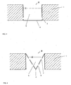
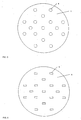
- storage containers 4 are distributed uniformly over the surface thereof, which are completely or partially open on their upper side and have outflow openings 5, 7 in their lower side and / or in their side surfaces.
- the addition of all the opening areas of all the outflow openings 5, 7 results in a total outflow area which is smaller than the total inlet area of the upper inlet opening / s 8.
- a preferred embodiment of the devices for guiding the liquid are similar to round pots 4 with vertical / vertical sidewall / walls Fig. 2 , In this potty holes 5 are provided in the bottom of the pot.
- the size of the holes and their number per pot depends on the particular application and is calculated individually.
- the mathematical dimensioning of the drainage holes / outflow openings 5, 7 corresponds to the dimensioning of drainage holes in conventional liquid distribution devices and is familiar to the person skilled in the art.
- round pots 4 with the smallest possible opening diameter and a large number of outflow openings 5.
- the dimensions of the pots is dependent on the total amount of liquid and type of column task.
- the storage containers 4 have a downwardly tapering shape, in particular they are conically or conically shaped.
- the outflow openings 5, 7 are arranged.
Landscapes
- Chemical & Material Sciences (AREA)
- Physics & Mathematics (AREA)
- Thermal Sciences (AREA)
- Organic Chemistry (AREA)
- Chemical Kinetics & Catalysis (AREA)
- Physical Or Chemical Processes And Apparatus (AREA)
- Devices For Dispensing Beverages (AREA)
Claims (10)
- Garniture d'une colonne pour l'échange de chaleur et/ou de matière comprenant des couches de garniture individuelles, en particulier de niveau, caractérisée en ce qu'à l'intérieur d'une couche de garniture (1) sont disposés des réservoirs de stockage individuels (4) qui sont ouverts totalement ou en partie en leur côté supérieur et présentent dans leur côté inférieur et/ou dans leurs surfaces latérales des ouvertures d'écoulement (5, 7), et que l'addition de toutes les surfaces d'ouverture de toutes les ouvertures d'écoulement (5, 7) donne une surface d'écoulement totale qui est plus petite que la surface d'admission totale de la/des ouvertures d'admission (8) supérieures.
- Garniture suivant la revendication 1, caractérisée en ce que les réservoirs de stockage(4) sont en forme de pot.
- Garniture suivant l'une des revendications 1 et 2, caractérisée en ce que le côté supérieur du réservoir de stockage(4) présente plusieurs ouvertures d'admission dont le diamètre est plus grand que le diamètre des ouvertures d'écoulement (5, 7).
- Garniture suivant l'une des revendications précédentes, caractérisée en ce que les réservoirs de stockage (4) sont régulièrement répartis sur la surface de la couche de garniture (1).
- Garniture suivant l'une des revendications précédentes, caractérisée en ce que les réservoirs de stockage se rétrécissent vers le bas.
- Garniture suivant l'une des revendications précédentes, caractérisée en ce que les réservoirs de stockage (4) sont disposés dans des couches de garniture (1) qui présentent une masse volumique et/ou une géométrie propre plus élevée qu'au moins une couche de garniture sus-jacente et/ou sous-jacente.
- Garniture suivant la revendication 6, caractérisée en ce que la couche de garniture avec le réservoir de stockage présente une surface supérieure spécifique qui est plus grande du facteur 1,5 à 10, de préférence du facteur 2 à 3, que la surface de la/des couches de garniture (2, 3) sus-jacente/s (3) et/ou sous-jacente/s (2).
- Garniture suivant l'une des revendications précédentes, caractérisée en ce que les réservoirs de stockage (4) présentent un débit de liquide par unité de surface plus élevé que des zones de la même couche de garniture (1) situées entre les réservoirs de stockage.
- Garniture suivant l'une des revendications précédentes, caractérisée en ce que les ouvertures d'écoulement (7) dans les parois latérales diffèrent en dimension sur la hauteur de la paroi latérale.
- Garniture suivant l'une des revendications précédentes,
caractérisée en ce que la couche de garniture (1) présentant des réservoirs de stockage (4) présente une hauteur plus faible que les couches de garniture (2, 3) sans réservoir de stockage.
Applications Claiming Priority (2)
| Application Number | Priority Date | Filing Date | Title |
|---|---|---|---|
| DE102004013381 | 2004-03-17 | ||
| DE200410013381 DE102004013381A1 (de) | 2004-03-17 | 2004-03-17 | Geordnete Packung für Wärme- und/oder Stoffaustausch |
Publications (2)
| Publication Number | Publication Date |
|---|---|
| EP1577006A1 EP1577006A1 (fr) | 2005-09-21 |
| EP1577006B1 true EP1577006B1 (fr) | 2011-10-19 |
Family
ID=34833183
Family Applications (1)
| Application Number | Title | Priority Date | Filing Date |
|---|---|---|---|
| EP20050005244 Expired - Lifetime EP1577006B1 (fr) | 2004-03-17 | 2005-03-10 | Elément de remplissage structuré pour échange de chaleur et de matière |
Country Status (2)
| Country | Link |
|---|---|
| EP (1) | EP1577006B1 (fr) |
| DE (1) | DE102004013381A1 (fr) |
Families Citing this family (1)
| Publication number | Priority date | Publication date | Assignee | Title |
|---|---|---|---|---|
| DE102004056419A1 (de) | 2004-11-23 | 2006-05-24 | Julius Montz Gmbh | Geordnete Packung für Wärme und/oder Stoffaustausch |
Family Cites Families (9)
| Publication number | Priority date | Publication date | Assignee | Title |
|---|---|---|---|---|
| NL42761C (fr) * | 1935-11-06 | |||
| DE1040514B (de) * | 1956-09-15 | 1958-10-09 | Uhde Gmbh Friedrich | Verfahren zur Durchfuehrung von Stoff- und/oder Waermeaustausch zwischen Gasen und Fluessigkeiten und/oder zur Durch-fuehrung katalytischer Reaktionen zwischen Gasen und Fluessigkeiten in der fluessigen Phase in einer Fuellkoerperschicht |
| DD110764A1 (fr) * | 1974-03-22 | 1975-01-12 | ||
| DE69510324T2 (de) * | 1995-04-10 | 1999-10-14 | Uop | Gas-Flüssigkeitskontaktboden mit Ablaufelementen mit seitlichem Ablauf und dreieckigem Querschnitt |
| US5851636A (en) * | 1995-12-29 | 1998-12-22 | Lantec Products, Inc. | Ceramic packing with channels for thermal and catalytic beds |
| US5876638A (en) * | 1996-05-14 | 1999-03-02 | Air Products And Chemicals, Inc. | Structured packing element with bi-directional surface texture and a mass and heat transfer process using such packing element |
| US5942164A (en) * | 1997-08-06 | 1999-08-24 | The United States Of America As Represented By The United States Department Of Energy | Combined heat and mass transfer device for improving separation process |
| DE19936380A1 (de) * | 1999-08-03 | 2001-02-08 | Basf Ag | Geordnete Packung zum Wärme- und Stoffaustausch |
| DE10010810A1 (de) * | 2000-03-08 | 2001-09-13 | Montz Gmbh Julius | Flüssigkeitsverteiler und Verfahren zum Betreiben |
-
2004
- 2004-03-17 DE DE200410013381 patent/DE102004013381A1/de not_active Withdrawn
-
2005
- 2005-03-10 EP EP20050005244 patent/EP1577006B1/fr not_active Expired - Lifetime
Also Published As
| Publication number | Publication date |
|---|---|
| DE102004013381A1 (de) | 2005-10-06 |
| EP1577006A1 (fr) | 2005-09-21 |
Similar Documents
| Publication | Publication Date | Title |
|---|---|---|
| DE3876989T2 (de) | Kunststoffplatte zur fuellung eines wasserkuehlturmes mit luftleitenden distanzstuecken. | |
| DE1302032C2 (de) | Kontaktkoerper | |
| EP0776695A1 (fr) | Elément de garnissage pour une colonne à haute pression et à contre-courant | |
| WO2017060361A1 (fr) | Dispositif réacteur destiné à la déshydrogénation d'un milieu vecteur | |
| EP1261404A1 (fr) | Separateur de liquides et son procede de fonctionnement | |
| CH667704A5 (de) | Verfahren und vorrichtung zur gleichmaessigen verteilung einer fluessigkeit auf eine querschnittsflaeche. | |
| EP0270531B1 (fr) | Reacteur a lit mobile | |
| DE8901136U1 (de) | Schüttgutbehälter mit Auslauftrichter | |
| EP3572760A1 (fr) | Emballage ppour une transmission de chaleur et / ou de substance | |
| EP0552457A1 (fr) | Plaque distributrice destinée à un réacteur à lit mobile | |
| EP1417015A1 (fr) | Plateau de colonne | |
| DE2017160B2 (de) | Vorrichtung zur Steuerung der Strömung eines Gases durch ein Flüssig¬ | |
| EP1577006B1 (fr) | Elément de remplissage structuré pour échange de chaleur et de matière | |
| WO1991002586A1 (fr) | Reacteur pour produits en vrac | |
| DE3536349A1 (de) | Festbettreaktor fuer biochemische prozesse | |
| EP0374443B1 (fr) | Dispositif pour porter des élements de remplissage et pour collecter ou distribuer des liquides dans un récipient échangeur de chaleur ou de masse | |
| EP0048239B1 (fr) | Appareil de contre-courant diphasé | |
| DE2734988A1 (de) | Kolonne fuer waerme- und stoffaustauschvorgaenge zwischen gas oder dampf und fluessigkeit | |
| DE3825724C2 (de) | Behälter | |
| EP0657210B1 (fr) | Elément de remplissage pour installations pour l'échange d'énergie et/ou de matière et/ou pour effectuer des réactions chimiques | |
| EP1814657A1 (fr) | Garnissage ordonne pour le transfert de chaleur et/ou de matiere | |
| DE2825734A1 (de) | Waermeschutzvorrichtung fuer kernreaktor | |
| DE2931157C2 (fr) | ||
| DE3210683A1 (de) | Wanderbettfilter zum trennen von stoffen dampf- und/oder gasfoermiger medien | |
| DE1982969U (de) | Zellenauslaufvorrichtung an silos mit rechteckigem querschnitt. |
Legal Events
| Date | Code | Title | Description |
|---|---|---|---|
| PUAI | Public reference made under article 153(3) epc to a published international application that has entered the european phase |
Free format text: ORIGINAL CODE: 0009012 |
|
| AK | Designated contracting states |
Kind code of ref document: A1 Designated state(s): AT BE BG CH CY CZ DE DK EE ES FI FR GB GR HU IE IS IT LI LT LU MC NL PL PT RO SE SI SK TR |
|
| AX | Request for extension of the european patent |
Extension state: AL BA HR LV MK YU |
|
| 17P | Request for examination filed |
Effective date: 20060111 |
|
| AKX | Designation fees paid |
Designated state(s): BE DE FR GB IT NL |
|
| 17Q | First examination report despatched |
Effective date: 20071127 |
|
| GRAP | Despatch of communication of intention to grant a patent |
Free format text: ORIGINAL CODE: EPIDOSNIGR1 |
|
| GRAS | Grant fee paid |
Free format text: ORIGINAL CODE: EPIDOSNIGR3 |
|
| GRAA | (expected) grant |
Free format text: ORIGINAL CODE: 0009210 |
|
| AK | Designated contracting states |
Kind code of ref document: B1 Designated state(s): BE DE FR GB IT NL |
|
| REG | Reference to a national code |
Ref country code: GB Ref legal event code: FG4D Free format text: NOT ENGLISH |
|
| REG | Reference to a national code |
Ref country code: NL Ref legal event code: T3 |
|
| REG | Reference to a national code |
Ref country code: DE Ref legal event code: R096 Ref document number: 502005012041 Country of ref document: DE Effective date: 20111215 |
|
| PLBE | No opposition filed within time limit |
Free format text: ORIGINAL CODE: 0009261 |
|
| STAA | Information on the status of an ep patent application or granted ep patent |
Free format text: STATUS: NO OPPOSITION FILED WITHIN TIME LIMIT |
|
| PG25 | Lapsed in a contracting state [announced via postgrant information from national office to epo] |
Ref country code: IT Free format text: LAPSE BECAUSE OF FAILURE TO SUBMIT A TRANSLATION OF THE DESCRIPTION OR TO PAY THE FEE WITHIN THE PRESCRIBED TIME-LIMIT Effective date: 20111019 |
|
| 26N | No opposition filed |
Effective date: 20120720 |
|
| REG | Reference to a national code |
Ref country code: DE Ref legal event code: R097 Ref document number: 502005012041 Country of ref document: DE Effective date: 20120720 |
|
| GBPC | Gb: european patent ceased through non-payment of renewal fee |
Effective date: 20120310 |
|
| PG25 | Lapsed in a contracting state [announced via postgrant information from national office to epo] |
Ref country code: GB Free format text: LAPSE BECAUSE OF NON-PAYMENT OF DUE FEES Effective date: 20120310 |
|
| REG | Reference to a national code |
Ref country code: FR Ref legal event code: PLFP Year of fee payment: 12 |
|
| REG | Reference to a national code |
Ref country code: FR Ref legal event code: PLFP Year of fee payment: 13 |
|
| REG | Reference to a national code |
Ref country code: FR Ref legal event code: PLFP Year of fee payment: 14 |
|
| PGFP | Annual fee paid to national office [announced via postgrant information from national office to epo] |
Ref country code: NL Payment date: 20240108 Year of fee payment: 20 |
|
| PGFP | Annual fee paid to national office [announced via postgrant information from national office to epo] |
Ref country code: DE Payment date: 20231229 Year of fee payment: 20 |
|
| PGFP | Annual fee paid to national office [announced via postgrant information from national office to epo] |
Ref country code: FR Payment date: 20240103 Year of fee payment: 20 Ref country code: BE Payment date: 20240105 Year of fee payment: 20 |
|
| REG | Reference to a national code |
Ref country code: DE Ref legal event code: R081 Ref document number: 502005012041 Country of ref document: DE Owner name: KOCH ENGINEERED SOLUTIONS GMBH, DE Free format text: FORMER OWNER: JULIUS MONTZ GMBH, 40723 HILDEN, DE |
|
| REG | Reference to a national code |
Ref country code: DE Ref legal event code: R071 Ref document number: 502005012041 Country of ref document: DE |
|
| REG | Reference to a national code |
Ref country code: NL Ref legal event code: MK Effective date: 20250309 |
|
| REG | Reference to a national code |
Ref country code: BE Ref legal event code: MK Effective date: 20250310 |