EP1576293B1 - Pompe a air a commande electrique et son procede de production - Google Patents
Pompe a air a commande electrique et son procede de production Download PDFInfo
- Publication number
- EP1576293B1 EP1576293B1 EP03788774A EP03788774A EP1576293B1 EP 1576293 B1 EP1576293 B1 EP 1576293B1 EP 03788774 A EP03788774 A EP 03788774A EP 03788774 A EP03788774 A EP 03788774A EP 1576293 B1 EP1576293 B1 EP 1576293B1
- Authority
- EP
- European Patent Office
- Prior art keywords
- air pump
- electric motor
- balancing
- pump
- housing
- Prior art date
- Legal status (The legal status is an assumption and is not a legal conclusion. Google has not performed a legal analysis and makes no representation as to the accuracy of the status listed.)
- Expired - Lifetime
Links
- 238000004519 manufacturing process Methods 0.000 title claims abstract description 17
- 238000000034 method Methods 0.000 title description 12
- 238000002485 combustion reaction Methods 0.000 claims abstract description 11
- 230000007246 mechanism Effects 0.000 claims abstract description 11
- 238000007789 sealing Methods 0.000 claims description 4
- 229920001971 elastomer Polymers 0.000 description 10
- 239000000806 elastomer Substances 0.000 description 10
- 238000005086 pumping Methods 0.000 description 9
- 239000000463 material Substances 0.000 description 7
- UGFAIRIUMAVXCW-UHFFFAOYSA-N Carbon monoxide Chemical compound [O+]#[C-] UGFAIRIUMAVXCW-UHFFFAOYSA-N 0.000 description 3
- 229910002091 carbon monoxide Inorganic materials 0.000 description 3
- 239000007789 gas Substances 0.000 description 3
- 150000002430 hydrocarbons Chemical class 0.000 description 3
- MWUXSHHQAYIFBG-UHFFFAOYSA-N nitrogen oxide Inorganic materials O=[N] MWUXSHHQAYIFBG-UHFFFAOYSA-N 0.000 description 3
- 238000010521 absorption reaction Methods 0.000 description 2
- 239000003054 catalyst Substances 0.000 description 2
- 230000006835 compression Effects 0.000 description 2
- 238000007906 compression Methods 0.000 description 2
- 238000011161 development Methods 0.000 description 2
- 230000018109 developmental process Effects 0.000 description 2
- 238000005516 engineering process Methods 0.000 description 2
- 229930195733 hydrocarbon Natural products 0.000 description 2
- 238000009434 installation Methods 0.000 description 2
- 238000002844 melting Methods 0.000 description 2
- 230000008018 melting Effects 0.000 description 2
- 229910052751 metal Inorganic materials 0.000 description 2
- 239000002184 metal Substances 0.000 description 2
- 230000008569 process Effects 0.000 description 2
- 230000009467 reduction Effects 0.000 description 2
- 238000003466 welding Methods 0.000 description 2
- 239000000853 adhesive Substances 0.000 description 1
- 238000004026 adhesive bonding Methods 0.000 description 1
- 230000001070 adhesive effect Effects 0.000 description 1
- 230000005540 biological transmission Effects 0.000 description 1
- 230000015572 biosynthetic process Effects 0.000 description 1
- 238000007664 blowing Methods 0.000 description 1
- 230000003197 catalytic effect Effects 0.000 description 1
- 238000001816 cooling Methods 0.000 description 1
- 230000008878 coupling Effects 0.000 description 1
- 230000001808 coupling effect Effects 0.000 description 1
- 238000010168 coupling process Methods 0.000 description 1
- 238000005859 coupling reaction Methods 0.000 description 1
- 238000013016 damping Methods 0.000 description 1
- 230000001419 dependent effect Effects 0.000 description 1
- 239000003344 environmental pollutant Substances 0.000 description 1
- 230000008020 evaporation Effects 0.000 description 1
- 238000001704 evaporation Methods 0.000 description 1
- 230000006872 improvement Effects 0.000 description 1
- 238000009413 insulation Methods 0.000 description 1
- 230000003993 interaction Effects 0.000 description 1
- 231100000719 pollutant Toxicity 0.000 description 1
- 230000001105 regulatory effect Effects 0.000 description 1
- 238000011144 upstream manufacturing Methods 0.000 description 1
Images

Classifications
-
- F—MECHANICAL ENGINEERING; LIGHTING; HEATING; WEAPONS; BLASTING
- F04—POSITIVE - DISPLACEMENT MACHINES FOR LIQUIDS; PUMPS FOR LIQUIDS OR ELASTIC FLUIDS
- F04D—NON-POSITIVE-DISPLACEMENT PUMPS
- F04D29/00—Details, component parts, or accessories
- F04D29/66—Combating cavitation, whirls, noise, vibration or the like; Balancing
- F04D29/661—Combating cavitation, whirls, noise, vibration or the like; Balancing especially adapted for elastic fluid pumps
- F04D29/662—Balancing of rotors
-
- F—MECHANICAL ENGINEERING; LIGHTING; HEATING; WEAPONS; BLASTING
- F04—POSITIVE - DISPLACEMENT MACHINES FOR LIQUIDS; PUMPS FOR LIQUIDS OR ELASTIC FLUIDS
- F04D—NON-POSITIVE-DISPLACEMENT PUMPS
- F04D29/00—Details, component parts, or accessories
- F04D29/66—Combating cavitation, whirls, noise, vibration or the like; Balancing
- F04D29/661—Combating cavitation, whirls, noise, vibration or the like; Balancing especially adapted for elastic fluid pumps
- F04D29/668—Combating cavitation, whirls, noise, vibration or the like; Balancing especially adapted for elastic fluid pumps damping or preventing mechanical vibrations
Definitions
- the invention relates to a method for producing an electrically driven secondary air pump for a motor vehicle having an internal combustion engine, having the features of the preamble of claim 1 or such an electrically driven air pump having the features of the preamble of claim 5.
- Generic air pumps or blowers are used for example as secondary air pumps or secondary air blower for blowing additional air into the exhaust passage of an internal combustion engine of a motor vehicle.
- This method minimizes the formation of nitrogen oxides or leads to a reduction in the content of carbon monoxide or hydrocarbons in the combustion residues before the exhaust gas enters the catalyst of the internal combustion engine.
- fresh air is supplied to the exhaust duct as close as possible behind the engine to eliminate the hydrocarbon compounds formed during the combustion process and the carbon monoxide.
- the secondary air supply into the exhaust line is practically set in an afterburning of the exhaust gases, in the course of which burned in the engine unburned carbon monoxide or hydrocarbons, i. be oxidized.
- the post-combustion by a secondary air supply system also increases the exhaust gas temperature, so that the required operating temperature for a controlled catalyst is reached early. Higher temperatures In the exhaust system, the regulated catalytic converter reacts faster, enabling it to fulfill its task of eliminating pollutants earlier in the driving cycle.
- An electrically driven air pump which has a housing in which on one side a pumping plant and on the other side an electric motor are arranged. Pump and motor side of the housing of the air pump EP 0 711 924 B1 are each closed by lids.
- the electric motor driving the pump mechanism is largely decoupled within the pump by means of two elastomer rings, which are supported between the electric motor and the pump housing.
- the electric motor of this electrically driven air pump of the prior art is balanced with mounted impeller, when installed, not yet closed pump side by the setting of balancing marks on an impeller of the pump factory, characterized in that the electric motor is balanced in the installed state with mounted impeller can the interaction of the electric motor with other components of the air pump are taken into account. Due to the balancing process on the mounted electric motor, the running quality of such an air pump can be reduced by reducing the vibrations that occur, but it is not possible to avoid specimen scattering from air pump to air pump.
- the invention is based on the object to provide a method for producing an electric secondary air pump with reduced vibrations and, consequently, also reduced running noise, wherein a balancing over the prior art facilitates bwz. is improved. It is also an object of the present invention to provide such an air pump.
- the air pump having a housing in which a pump unit with at least one fan and an electric motor driving the at least one fan are integrated, balanced with the already built into the housing electric motor by balancing in at least two axially spaced planes , According to the invention it is provided that the air pump is balanced after mounting the at least one fan wheel on a shaft of the electric motor with built-in electric motor by balancing on a fan and an axially spaced from the fan wheel balancing disk.
- an air pump is claimed with the features of claim 5, wherein according to the invention in the region of the pumping station remote from the end of the drive shaft of the electric motor, a balancing disc is arranged and a balancing takes place both on the fan and on the fan wheel axially spaced balancing disc due to this Two-level balancing can significantly increase the balancing quality of the electrically driven air pump according to the invention, so that specimen scattering in the running noise of the pump can be further reduced.
- the balancing wheel is mounted on the side facing away from the pump mechanism side of the shaft of the electric motor. In this way, the two balancing planes have a large axial distance from one another.
- the electric motor of the air pump is decoupled by means of elastic means from the pump housing vibration technology. This leads to a further reduction of the vibrations of the drive motor to the pump housing.
- the balancing speed and / or the type of balancing absorption during balancing of the air pump is matched to the natural frequency of the decoupling means.
- the air pump according to the invention is balanced in a speed range well below the resonant frequency of Enticopplungsstoff. In this way it is possible to minimize the influence of the elastic coupling means between the electric motor and the pump housing on the running behavior of the air pump.
- the elastic means for supporting the electric motor are also designed such that the pump unit of the air pump is sealed relative to the motor part.
- the elastic means in the form of two axially spaced-apart elastomeric rings are formed.
- the fan-side elastomeric ring has in an advantageous embodiment of the air pump according to the invention a sealing lip which seals the pumping unit of the air pump relative to the motor part.
- At least one elastomer ring may have means for torque support of the drive motor, so that the motor is securely fixed especially in its start-up phase.
- the claimed method of manufacturing an electrically driven air pump provides an air pump which, due to its complete balancing in two levels, ensures an extremely smooth running due to the strong structure-borne sound insulation caused by the mechanical decoupling of the electric motor and the additional, in the assembled state complete balancing achieved in two levels, it is possible to use the inventive air pump without complex decoupling for the body attachment.
- the drawing shows an embodiment of an inventive electrically driven air pump for the compression of combustion air is shown.
- This air pump and the inventive method for producing such an air pump will be explained in more detail in the following description.
- the figures of the drawing, the description and the claims directed thereto contain numerous features in combination. A person skilled in the art will also consider these features individually and combine them into meaningful, further combinations.
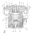
- FIG. 1 shows a longitudinal section through an embodiment of an inventive electrically driven air pump 10 in the assembled state.
- the air pump 10 comprises a pump part 11 and a drive or motor part 15, which are surrounded by a housing 12.
- the pump part 11 consists essentially of a pump unit 13 and corresponding inlet and outlet openings for the air to be delivered.
- the pump housing 12 is, according to the embodiment FIG. 1 essentially formed in three pieces.
- the housing 12 has a pump-side cover 20 and a drive motor-side cover 22.
- the pump-side lid 20 has a central opening 44 through which the air to be compressed is sucked.
- the housing 12 of the air pump 10 according to the invention is advantageously made of a plastic
- the driving electric motor 16 is inserted, which in the embodiment of FIG. 1 is designed as an internal rotor and at least via a rotor 19 and a, the rotor encompassing stator 21 has.
- the stator 21 is in the embodiment of the pump according to the invention after FIG. 1 realized by magnets 25.
- the motor housing 17 of the electric motor 16 is formed by a pole housing 30 of the motor.
- Other motor types than the internal rotor shown in the embodiment are for the inventive air pump but also conceivable.
- the electric motor 16 drives via a shaft 23, the pump unit 13 to compress the air.
- the electric motor 16 is decoupled via elastic means 24 from the housing 12 of the air pump.
- Elastomer rings 26 and 28 are used for vibration damping.
- the elastomer rings 26 and 28 are on the end faces of the pole housing 30 of the electric motor 16 between the pole housing 30 and Pump housing 12 is placed.
- the elastomer rings are formed and introduced such that both a radial and an axial support of the electric motor 16 takes place in the pump housing.
- the motor-side decoupling 28 is executed in its shape so that a torque support of the electric motor 16 is provided on the housing.
- the torque support can of course also be formed on the pump-side elastomer ring 26 or on both elastomer rings.
- the pumping-side elastomer ring 26 has a sealing lip 27, which causes the elastic means 24 to improve the smoothness of the air pump 10 according to the invention also serve as sealing elements between the motor part 15 and the pump unit 13 of the air pump according to the invention.
- the pumping-side elastomeric ring 26 is arranged in the region of a bearing plate 32 of the drive motor which is aligned with the pumping station 13.
- a retaining cover 34 is installed on the side facing away from the pump unit 13 of the motor housing 17.
- the retaining cover 34 is pressed against the elastomer ring 28 and locked with the central housing part 14 of the pump housing 12. In this way, the electric motor 16 is fixed in the axial direction.
- the shaft 23 of the drive motor 16 of the air pump 10 according to the invention is led out of this at both axial ends of the motor housing 17 and carries on its one, in the figure of FIG. 1 right side, wheels 36 and 38 of the pump factory 13.
- the pump unit 13 of the air pump according to the invention according to the embodiment of FIG. 1 is executed in two stages. Between the two wheels 36 and 38 of the pump factory, a stator 40 is arranged, which is firmly connected to the housing 12 of the air pump.
- the stator 40 has structures in the form of channels 42, which ensure that the radially outwardly from the first impeller 36 conveyed air from the outer region of the first impeller in the inner impeller region of the second impeller 38 is promoted, so that an effective two-stage compression the sucked air can take place.
- the radially outwardly guided by the second impeller 38, compressed air is conveyed in a, in the circumferential direction of the housing 12 of the air pump 10 extending, annular air duct 18 whose diameter in the circumferential direction of the pump housing 12 increases.
- This air duct 18 (volute) opens into a, in FIG. 1 not shown on the pressure side connection of the air pump.
- the air pump 10 according to the invention is not limited to a two-stage pump unit 13. More or less pump stages can of course also be used in a pump according to the invention.
- each further impeller is also assigned a further stator, which conveys the radially outwardly conveyed air of the upstream impeller into the radially inner region of the downstream impeller.
- the pump-side lid 20 is designed such that on its inside, i. the side facing the first impeller 36 of the pump unit 13, structures 47 are formed, which prevent a backflow of the air compressed via the first impeller in the intake of the pump unit.
- the housing of the air pump is closed on the pumping side by a cover 20 which has a central opening 44 for sucking the air to be compressed.
- the central opening 44 in the cover 20 of the pump housing 12 is in the embodiment of FIG. 1 designed as a nozzle 46, which makes it possible to install corresponding connection means, such as hoses, quickly and easily to the pump according to the invention.
- the pump housing 12, the stator 40 of the pump unit 13 and the pump-side cover 20 are connected to each other towards the end of the inventive method for producing an electrically driven air pump.
- connection technology here all known to those skilled in the techniques can be used.
- a balancing disk 50 is installed on the drive shaft 23 of the motor 16, which is rotatably connected to the drive shaft.
- This balancing disc 50 may be made of metal, for example of a sheet metal, and has a diameter which is typically smaller than the diameter of the rotor 19 of the drive motor 16.
- the balancing disc 50 is known to one skilled in the art Fixing method rotatably connected to the drive shaft 23.
- Balancing marks for example by removal of material, can be placed on the balancing disk 50 to compensate for the imbalance of the air pump 10 according to the invention.
- the pump unit 13 remote from the end of the housing 12 of the air pump 10 according to the invention is closed by a cover 22 after installation of the air pump.
- the assembled drive motor 16 is first provided with the decoupling rings 26 and 28, respectively.
- the electric motor 16 per se can already be pre-balanced so that a first balancing operation is carried out, for example, by removal of material or material on the motor shaft or on the rotor or also at the armature of the motor.
- pre-balancing of the electric motor 16 can be dispensed with, so that only the balancing of the air pump 10 to be described with the mounted electric motor 16 and the mounted pump wheel 36 or 38 need be performed.
- the preassembled electric motor 16 is inserted through an opening 52 of the pump housing 12 facing away from the pump housing 13 into the pump housing 12 and secured in the axial and radial direction by latching of the retaining cover 34 on the housing.
- the locking of the retaining cover 34 is to be selected so that the elastomer rings 26 and 28 are pressed under a certain bias against the inside of the pump housing 12.
- the impeller 38, the stator 40 and the impeller 36 are mounted on the pumping unit end of the drive shaft 23 of the electric motor 16.
- the air pump is balanced with the pump unit 13 installed when the electric motor 16 is installed.
- FIG. 2 shows the pump according to the invention with built-in electric motor 16 and mounted pump unit 13, as used for balancing example in a balancing machine.
- the balancing operation is carried out successively or in parallel in two, substantially perpendicular to the drive shaft 23 of the air pump 10 arranged balancing planes A and B respectively.
- the balancing plane A is formed by the balancing wheel 50 at the end of the drive shaft 23 facing away from the pump mechanism 13.
- the second balancing plane B is described in the exemplary embodiment of FIG FIG. 2 through the cover plate 54 of the impeller 36 of the pump unit 13 of the invention Air pump 10 is formed.
- the balancing plane B can also coincide with the base disk 56 of the impeller 36.
- the air pump 10 according to the invention is balanced by the setting of balancing marks in one or both balancing planes.
- material from the balancing disk 50 or the cover disk 54 can be "nibbled".
- the balancing speed and the type of balancing absorption is matched to the natural frequency of the decoupling of the electric motor 16 by the elastic means 24.
- the balancing of the air pump according to the invention in the speed range of the natural frequency of the decoupling means 24 is prohibited.
- a material removal by evaporation by means of a high-intensity light or laser beam is another possible method for setting balance marks in the method according to the invention. Furthermore, it is also possible to realize balancing marks by the application of the adhesive points, in particular on a fan or the balancing disk.
- the stator 40 is fixed axially and radially between the housing part 14 and the lid 20 so that it is secured against rotation.
- the stator 40 can be fitted at its outer periphery 58 in corresponding recesses 60 of the central housing part 14 of the pump housing 12 and in recesses 62 of the pump-side cover 20 and clamped by the assembly of the lid 20.
- the bracing, screwing, riveting, gluing, ultrasonic welding or friction welding are mentioned here as possible fastening methods.
- the air pump according to the invention is not limited to the embodiments illustrated in the figures.
- the air pump according to the invention is not limited to the use of a two-stage pumping station.
- the inventive method for producing an electrically driven air pump is not limited to the mechanical mass removal on the fan or the balancing disk.
- balancing masses for example, a melting of material to improve the balancing quality, in particular an optically induced melting, conceivable.
Landscapes
- Engineering & Computer Science (AREA)
- Mechanical Engineering (AREA)
- General Engineering & Computer Science (AREA)
- Structures Of Non-Positive Displacement Pumps (AREA)
Abstract
Claims (9)
- Procédé de fabrication d'une pompe à air auxiliaire (10) pour un véhicule automobile comprenant un moteur à combustion interne, la pompe à air (10) présentant un boîtier (12) dans lequel sont disposés un mécanisme de pompe (13) avec au moins une roue de ventilateur (36, 38) ainsi qu'un moteur électrique (16) entraînant l'au moins une roue de ventilateur (36, 38), et la pompe à air (10) étant équilibrée avec le moteur électrique (16) incorporé dans le boîtier (12) par équilibrage dans au moins deux plans (A, B) espacés axialement l'un de l'autre, caractérisé en ce que la pompe à air (10), après le montage de l'au moins une roue de ventilateur (36, 38) sur un arbre (23) du moteur électrique (16), lorsque le moteur électrique (16) est incorporé, est équilibrée par équilibrage au niveau d'une roue de ventilateur (36, 38) et d'un disque d'équilibrage (50) espacé axialement de la roue de ventilateur (36, 38).
- Procédé de fabrication d'une pompe à air à commande électrique selon la revendication 1, caractérisé en ce que le disque d'équilibrage (50) est monté sur le côté de l'arbre (23) du moteur électrique (16) opposé au mécanisme de pompe (13).
- Procédé de fabrication d'une pompe à air à commande électrique selon l'une quelconque des revendications précédentes, caractérisé en ce que le moteur électrique (16) est désaccouplé du boîtier de pompe (12) par le biais de moyens élastiques (24).
- Procédé de fabrication d'une pompe à air à commande électrique selon la revendication 3, caractérisé en ce que la vitesse de rotation d'équilibrage et/ou le type de mise en oeuvre de l'équilibrage lors de l'équilibrage de la pompe à air (10) est adapté à la fréquence propre des moyens de désaccouplement (24).
- Pompe à air (10) à commande électrique, en particulier pompe à air auxiliaire (10) pour un véhicule automobile comprenant un moteur à combustion interne, comprenant un boîtier (12) et un moteur électrique (16) intégré dans le boîtier (12), qui est supporté par le biais de moyens élastiques (24) dans le boîtier de pompe (12), et comprenant un mécanisme de pompe (13) avec au moins une roue de ventilateur (36, 38) fixée sur un arbre (23) du moteur d'entraînement (16), caractérisée en ce que dans la région de l'extrémité de l'arbre d'entraînement (23) du moteur électrique (16) opposée au mécanisme de pompe (13) est disposé un disque d'équilibrage (50) et un équilibrage a lieu à la fois au niveau de la roue de ventilateur (36, 38) et au niveau du disque d'équilibrage (50) espacé axialement de la roue de ventilateur (36, 38).
- Pompe à air à commande électrique selon la revendication 5, caractérisée en ce que des moyens élastiques (24) sont prévus, lesquels, pour supporter le moteur électrique (16), scellent le mécanisme de pompe (13) de la pompe à air (10) vis-à-vis de la partie du moteur (15).
- Pompe à air à commande électrique selon l'une quelconque des revendications précédentes 5 à 8, caractérisée en ce que les moyens élastiques (24) sont réalisés en vue de supporter le moteur électrique (16) sous la forme de deux bagues élastomères (26, 28) espacées axialement l'une de l'autre.
- Pompe à air à commande électrique selon la revendication 7, caractérisée en ce qu'une lèvre d'étanchéité (27) est réalisée sur la bague élastomère (26) du côté de la roue de ventilateur.
- Pompe à air à commande électrique selon l'une quelconque des revendications 7 ou 8, caractérisée en ce qu'au moins au niveau d'une bague élastomère (26, 28) sont réalisés des moyens de support de couple du moteur d'entraînement (16).
Applications Claiming Priority (3)
| Application Number | Priority Date | Filing Date | Title |
|---|---|---|---|
| DE10259179A DE10259179A1 (de) | 2002-12-18 | 2002-12-18 | Elektrisch angetriebene Luftpumpe und Verfahren zur Herstellung einer elektrisch angetriebenen Luftpumpe |
| DE10259179 | 2002-12-18 | ||
| PCT/DE2003/003678 WO2004057195A1 (fr) | 2002-12-18 | 2003-11-07 | Pompe a air a commande electrique et son procede de production |
Publications (2)
| Publication Number | Publication Date |
|---|---|
| EP1576293A1 EP1576293A1 (fr) | 2005-09-21 |
| EP1576293B1 true EP1576293B1 (fr) | 2012-08-22 |
Family
ID=32477746
Family Applications (1)
| Application Number | Title | Priority Date | Filing Date |
|---|---|---|---|
| EP03788774A Expired - Lifetime EP1576293B1 (fr) | 2002-12-18 | 2003-11-07 | Pompe a air a commande electrique et son procede de production |
Country Status (5)
| Country | Link |
|---|---|
| US (1) | US7520734B2 (fr) |
| EP (1) | EP1576293B1 (fr) |
| JP (1) | JP2006510839A (fr) |
| DE (1) | DE10259179A1 (fr) |
| WO (1) | WO2004057195A1 (fr) |
Families Citing this family (23)
| Publication number | Priority date | Publication date | Assignee | Title |
|---|---|---|---|---|
| JP2005171835A (ja) * | 2003-12-10 | 2005-06-30 | Fujitsu General Ltd | 送風装置 |
| CN100474743C (zh) * | 2004-01-29 | 2009-04-01 | 皇家飞利浦电子股份有限公司 | 制造用于真空吸尘器的电抽吸单元的方法及真空吸尘器 |
| DE102004044070B3 (de) * | 2004-09-11 | 2006-01-19 | Pierburg Gmbh | Unwuchtausgleichselement, Pumpe und Verfahren zum Auswuchten einer Pumpe |
| EP1901877B1 (fr) * | 2005-07-11 | 2017-10-04 | ebm-papst St. Georgen GmbH & Co. KG | Procede et ensemble pour equilibrer un ventilateur |
| JP2010532446A (ja) * | 2007-07-02 | 2010-10-07 | ボーグワーナー・インコーポレーテッド | ポンプアセンブリ用の流入部の設計 |
| DE102008021682A1 (de) * | 2008-04-30 | 2009-11-05 | Magna Powertrain Ag & Co Kg | Verfahren zur Montage einer Baueinheit |
| JP2010071170A (ja) * | 2008-09-18 | 2010-04-02 | Denso Corp | 遠心式送風機 |
| JP5304177B2 (ja) * | 2008-10-29 | 2013-10-02 | 株式会社Ihi | 排気浄化装置 |
| JP2010265833A (ja) * | 2009-05-15 | 2010-11-25 | Mikuni Corp | 電動ポンプ |
| WO2011067370A1 (fr) | 2009-12-04 | 2011-06-09 | Emitec Gesellschaft Für Emissionstechnologie Mbh | Dispositif de refoulement servant à refouler un agent réducteur |
| US8355859B2 (en) * | 2010-11-02 | 2013-01-15 | Ford Global Technologies, Llc | Accessory drive for a stop/start vehicle |
| US8267072B2 (en) * | 2010-11-02 | 2012-09-18 | Ford Global Technologies, Llc | Efficient vacuum for a vehicle |
| US9103246B2 (en) | 2010-11-02 | 2015-08-11 | Ford Global Technologies, Llc | System and method for reducing vacuum degradation in a vehicle |
| DE202011101568U1 (de) | 2011-05-30 | 2011-10-20 | Kress-Elektrik Gmbh & Co. Kg | E-Motor mit Wuchtmaterial |
| DE102013109401A1 (de) * | 2013-08-02 | 2015-02-19 | Ebm-Papst Landshut Gmbh | Radialgebläse in kompakter Bauweise |
| DE102013109402A1 (de) * | 2013-08-02 | 2015-02-05 | Ebm-Papst Landshut Gmbh | Radialgebläse mit kombinierter Dichtung und Schwingungsentkopplung |
| EP3208472B1 (fr) * | 2014-10-14 | 2023-04-05 | Panasonic Intellectual Property Management Co., Ltd. | Soufflante centrifuge et automobile la comportant |
| EP3695696A1 (fr) | 2019-02-12 | 2020-08-19 | Instant Seed GmbH | Pastilles de matériau d'ensemencement |
| DE102019108669A1 (de) | 2019-04-03 | 2020-10-08 | Alfmeier Präzision SE | Kompressor mit vereinfachter Auswuchtung und Verfahren zum Herstellen eines solchen Kompressors |
| JP7396909B2 (ja) * | 2020-01-24 | 2023-12-12 | ミネベアミツミ株式会社 | 回転機器 |
| DE102021000764A1 (de) | 2021-02-15 | 2022-08-18 | Mercedes-Benz Group AG | Verbrennungskraftmaschine für ein Kraftfahrzeug |
| DE102021213966A1 (de) | 2021-12-08 | 2023-06-15 | Robert Bosch Gesellschaft mit beschränkter Haftung | Pumpe |
| US11585257B1 (en) * | 2022-03-14 | 2023-02-21 | Garrett Transportation I Inc. | Methods and systems for catalytically treating exhaust gases from an internal combustion engine using secondary air injection, and secondary air pump for use therein |
Family Cites Families (10)
| Publication number | Priority date | Publication date | Assignee | Title |
|---|---|---|---|---|
| US1603076A (en) | 1922-11-27 | 1926-10-12 | Motor Player Corp | Means and method for dynamically balancing incased fan blades |
| US2809590A (en) * | 1954-01-29 | 1957-10-15 | Robert J Brown | Electric motor driven pump |
| JP2716237B2 (ja) * | 1990-02-27 | 1998-02-18 | ファナック株式会社 | モータのバランス構造 |
| DE4107049C2 (de) * | 1991-03-06 | 1997-12-11 | Pierburg Ag | Elektrisch angetriebene Luftpumpe |
| DE9303470U1 (de) | 1993-03-10 | 1994-07-14 | Robert Bosch Gmbh, 70469 Stuttgart | Gebläse |
| US5487640A (en) * | 1994-03-16 | 1996-01-30 | Dresser-Rand Company | Balancing rings for assembled steam turbines |
| DE4438750A1 (de) | 1994-10-29 | 1996-05-02 | Pierburg Gmbh | Elektrisch angetriebene Luftpumpe |
| DE4438747A1 (de) * | 1994-10-29 | 1996-05-02 | Pierburg Gmbh | Elektrisch angetriebene Luftpumpe |
| DE19501959C2 (de) * | 1995-01-24 | 1998-07-02 | Bosch Gmbh Robert | Verfahren zum Auswuchten einer elektrisch angetriebenen Luftgebläseeinheit |
| TR200103449T2 (tr) | 1999-05-31 | 2002-05-21 | Arçeli̇k Anoni̇m Şi̇rketi̇ | Montajdan kaynaklanan balans bozuklukları azaltılan ıslak-kuru elektrikli süpürge motoru. |
-
2002
- 2002-12-18 DE DE10259179A patent/DE10259179A1/de not_active Withdrawn
-
2003
- 2003-11-07 EP EP03788774A patent/EP1576293B1/fr not_active Expired - Lifetime
- 2003-11-07 JP JP2004561019A patent/JP2006510839A/ja active Pending
- 2003-11-07 US US10/539,657 patent/US7520734B2/en not_active Expired - Fee Related
- 2003-11-07 WO PCT/DE2003/003678 patent/WO2004057195A1/fr not_active Ceased
Also Published As
| Publication number | Publication date |
|---|---|
| US7520734B2 (en) | 2009-04-21 |
| JP2006510839A (ja) | 2006-03-30 |
| WO2004057195A1 (fr) | 2004-07-08 |
| EP1576293A1 (fr) | 2005-09-21 |
| US20060115368A1 (en) | 2006-06-01 |
| DE10259179A1 (de) | 2004-07-08 |
Similar Documents
| Publication | Publication Date | Title |
|---|---|---|
| WO2004057195A1 (fr) | Pompe a air a commande electrique et son procede de production | |
| EP0182145B1 (fr) | Roue de ventilateur de matière synthétique en une pièce | |
| DE102007052110A1 (de) | Strahltriebwerksanordnung und Verfahren, dies zu Montieren | |
| WO2003087541A1 (fr) | Turbocompresseur pourvu d'un moyen sur l'arbre permettant la fixation axiale de cet arbre en cas de rupture de la roue de compresseur | |
| EP1455094A1 (fr) | Roue ventilateur radial | |
| DE10325985A1 (de) | Leitapparat für eine Abgasturbine | |
| EP1736635B1 (fr) | Système de transfert d'air entre le compresseur et la turbine d'une turbine à gaz | |
| EP1395454A1 (fr) | Systeme d'entrainement hybride a convertisseur de couple | |
| CH685254A5 (de) | Verfahren zum Umändern eines Luftfahrzeug-Turbofan-Triebwerks und umgeändertes Luftfahrzeug-Triebwerk. | |
| DE102019213724A1 (de) | Kreiselpumpe mit schalldämmender Laufradbuchse mit Gummiisolierung | |
| DE102008046508A1 (de) | Lüftervorrichtung zur Belüftung eines Verbrennungsmotors, Kühlsystem mit zumindest einer Lüftervorrichtung | |
| DE102007019884A1 (de) | Verdichter für einen Abgasturbolader | |
| EP1586745B1 (fr) | Carter de compresseur | |
| EP1282765B1 (fr) | Turbocompresseur destine a un moteur a combustion interne a pistons | |
| DE102016212552A1 (de) | Elektro-Verdichter mit schwingungsgedämpfter, kompakter Lagerung | |
| DE19938624C2 (de) | Abgasturbolader | |
| WO2021032714A1 (fr) | Compresseur électrique comprenant un manchon de réception de palier séparé | |
| EP1144872B1 (fr) | Ventilateur | |
| DE102012022647A1 (de) | Abgasturbolader für eine Verbrennungskraftmaschine | |
| DE102010013698A1 (de) | Abgasturbolader, Kraftfahrzeug und Verfahren zur Montage eines Abgasturboladers | |
| EP1709300B1 (fr) | Dispositif pour deplacer des aubes directrices | |
| DE102011120766A1 (de) | Einrichtung zur Verlängerung der Reichweite eines Elektrofahrzeugs | |
| DE102011109704A1 (de) | Verdichter für eine Strömungsmaschine, insbesondere einen Abgasturbolader | |
| WO2018099592A1 (fr) | Turbocompresseur à gaz d'échappement | |
| DE102019212504A1 (de) | Elektro-Verdichter mit einer Lageraufnahmehülse |
Legal Events
| Date | Code | Title | Description |
|---|---|---|---|
| PUAI | Public reference made under article 153(3) epc to a published international application that has entered the european phase |
Free format text: ORIGINAL CODE: 0009012 |
|
| 17P | Request for examination filed |
Effective date: 20050718 |
|
| AK | Designated contracting states |
Kind code of ref document: A1 Designated state(s): AT BE BG CH CY CZ DE DK EE ES FI FR GB GR HU IE IT LI LU MC NL PT RO SE SI SK TR |
|
| RBV | Designated contracting states (corrected) |
Designated state(s): DE ES FR |
|
| 17Q | First examination report despatched |
Effective date: 20091117 |
|
| GRAP | Despatch of communication of intention to grant a patent |
Free format text: ORIGINAL CODE: EPIDOSNIGR1 |
|
| GRAS | Grant fee paid |
Free format text: ORIGINAL CODE: EPIDOSNIGR3 |
|
| GRAA | (expected) grant |
Free format text: ORIGINAL CODE: 0009210 |
|
| AK | Designated contracting states |
Kind code of ref document: B1 Designated state(s): DE ES FR |
|
| REG | Reference to a national code |
Ref country code: DE Ref legal event code: R096 Ref document number: 50314470 Country of ref document: DE Effective date: 20121018 |
|
| PG25 | Lapsed in a contracting state [announced via postgrant information from national office to epo] |
Ref country code: ES Free format text: LAPSE BECAUSE OF FAILURE TO SUBMIT A TRANSLATION OF THE DESCRIPTION OR TO PAY THE FEE WITHIN THE PRESCRIBED TIME-LIMIT Effective date: 20121203 |
|
| PLBE | No opposition filed within time limit |
Free format text: ORIGINAL CODE: 0009261 |
|
| STAA | Information on the status of an ep patent application or granted ep patent |
Free format text: STATUS: NO OPPOSITION FILED WITHIN TIME LIMIT |
|
| 26N | No opposition filed |
Effective date: 20130523 |
|
| REG | Reference to a national code |
Ref country code: FR Ref legal event code: ST Effective date: 20130731 |
|
| REG | Reference to a national code |
Ref country code: DE Ref legal event code: R097 Ref document number: 50314470 Country of ref document: DE Effective date: 20130523 |
|
| PG25 | Lapsed in a contracting state [announced via postgrant information from national office to epo] |
Ref country code: FR Free format text: LAPSE BECAUSE OF NON-PAYMENT OF DUE FEES Effective date: 20121130 |
|
| REG | Reference to a national code |
Ref country code: DE Ref legal event code: R084 Ref document number: 50314470 Country of ref document: DE |
|
| REG | Reference to a national code |
Ref country code: DE Ref legal event code: R084 Ref document number: 50314470 Country of ref document: DE Effective date: 20150211 |
|
| PGFP | Annual fee paid to national office [announced via postgrant information from national office to epo] |
Ref country code: DE Payment date: 20190124 Year of fee payment: 16 |
|
| REG | Reference to a national code |
Ref country code: DE Ref legal event code: R119 Ref document number: 50314470 Country of ref document: DE |
|
| PG25 | Lapsed in a contracting state [announced via postgrant information from national office to epo] |
Ref country code: DE Free format text: LAPSE BECAUSE OF NON-PAYMENT OF DUE FEES Effective date: 20200603 |