EP1575647B1 - Magnetisches automatisches absperrventil - Google Patents
Magnetisches automatisches absperrventil Download PDFInfo
- Publication number
- EP1575647B1 EP1575647B1 EP03787268A EP03787268A EP1575647B1 EP 1575647 B1 EP1575647 B1 EP 1575647B1 EP 03787268 A EP03787268 A EP 03787268A EP 03787268 A EP03787268 A EP 03787268A EP 1575647 B1 EP1575647 B1 EP 1575647B1
- Authority
- EP
- European Patent Office
- Prior art keywords
- float
- container
- fluid
- valve
- attraction
- Prior art date
- Legal status (The legal status is an assumption and is not a legal conclusion. Google has not performed a legal analysis and makes no representation as to the accuracy of the status listed.)
- Expired - Lifetime
Links
- 239000012530 fluid Substances 0.000 claims abstract description 146
- 238000007789 sealing Methods 0.000 claims description 62
- 239000012528 membrane Substances 0.000 claims description 23
- 238000011144 upstream manufacturing Methods 0.000 claims description 13
- 238000000034 method Methods 0.000 claims description 11
- 239000000463 material Substances 0.000 claims description 9
- 230000003993 interaction Effects 0.000 claims 2
- 230000001105 regulatory effect Effects 0.000 claims 1
- 238000004519 manufacturing process Methods 0.000 abstract description 11
- 230000007423 decrease Effects 0.000 abstract description 9
- 238000007667 floating Methods 0.000 description 5
- 230000005484 gravity Effects 0.000 description 5
- 238000001802 infusion Methods 0.000 description 5
- 230000000694 effects Effects 0.000 description 4
- 239000000853 adhesive Substances 0.000 description 3
- 230000001070 adhesive effect Effects 0.000 description 3
- 238000013459 approach Methods 0.000 description 3
- 238000004891 communication Methods 0.000 description 3
- 229910052751 metal Inorganic materials 0.000 description 3
- 210000003462 vein Anatomy 0.000 description 3
- CWYNVVGOOAEACU-UHFFFAOYSA-N Fe2+ Chemical compound [Fe+2] CWYNVVGOOAEACU-UHFFFAOYSA-N 0.000 description 2
- 238000010586 diagram Methods 0.000 description 2
- 230000004907 flux Effects 0.000 description 2
- 239000007788 liquid Substances 0.000 description 2
- 239000002184 metal Substances 0.000 description 2
- 229920000052 poly(p-xylylene) Polymers 0.000 description 2
- 229920001296 polysiloxane Polymers 0.000 description 2
- 238000003466 welding Methods 0.000 description 2
- 208000005189 Embolism Diseases 0.000 description 1
- 239000004743 Polypropylene Substances 0.000 description 1
- 230000006978 adaptation Effects 0.000 description 1
- 230000002411 adverse Effects 0.000 description 1
- 230000009286 beneficial effect Effects 0.000 description 1
- 230000000903 blocking effect Effects 0.000 description 1
- 239000008280 blood Substances 0.000 description 1
- 210000004369 blood Anatomy 0.000 description 1
- 210000001124 body fluid Anatomy 0.000 description 1
- 239000010839 body fluid Substances 0.000 description 1
- 239000011248 coating agent Substances 0.000 description 1
- 238000000576 coating method Methods 0.000 description 1
- 230000000295 complement effect Effects 0.000 description 1
- 230000003111 delayed effect Effects 0.000 description 1
- 230000001419 dependent effect Effects 0.000 description 1
- 238000011161 development Methods 0.000 description 1
- 229920005570 flexible polymer Polymers 0.000 description 1
- 239000011553 magnetic fluid Substances 0.000 description 1
- 239000000696 magnetic material Substances 0.000 description 1
- 230000013011 mating Effects 0.000 description 1
- 238000012986 modification Methods 0.000 description 1
- 230000004048 modification Effects 0.000 description 1
- 238000012544 monitoring process Methods 0.000 description 1
- 238000000465 moulding Methods 0.000 description 1
- 230000000149 penetrating effect Effects 0.000 description 1
- -1 polypropylene Polymers 0.000 description 1
- 229920001155 polypropylene Polymers 0.000 description 1
- 230000037452 priming Effects 0.000 description 1
- 238000009877 rendering Methods 0.000 description 1
- 239000007787 solid Substances 0.000 description 1
- 238000002560 therapeutic procedure Methods 0.000 description 1
- 229920001169 thermoplastic Polymers 0.000 description 1
- 229920002725 thermoplastic elastomer Polymers 0.000 description 1
- 239000002982 water resistant material Substances 0.000 description 1
Images




Classifications
-
- A—HUMAN NECESSITIES
- A61—MEDICAL OR VETERINARY SCIENCE; HYGIENE
- A61M—DEVICES FOR INTRODUCING MEDIA INTO, OR ONTO, THE BODY; DEVICES FOR TRANSDUCING BODY MEDIA OR FOR TAKING MEDIA FROM THE BODY; DEVICES FOR PRODUCING OR ENDING SLEEP OR STUPOR
- A61M5/00—Devices for bringing media into the body in a subcutaneous, intra-vascular or intramuscular way; Accessories therefor, e.g. filling or cleaning devices, arm-rests
- A61M5/36—Devices for bringing media into the body in a subcutaneous, intra-vascular or intramuscular way; Accessories therefor, e.g. filling or cleaning devices, arm-rests with means for eliminating or preventing injection or infusion of air into body
- A61M5/40—Devices for bringing media into the body in a subcutaneous, intra-vascular or intramuscular way; Accessories therefor, e.g. filling or cleaning devices, arm-rests with means for eliminating or preventing injection or infusion of air into body using low-level float-valve to cut off media flow from reservoir
-
- A—HUMAN NECESSITIES
- A61—MEDICAL OR VETERINARY SCIENCE; HYGIENE
- A61M—DEVICES FOR INTRODUCING MEDIA INTO, OR ONTO, THE BODY; DEVICES FOR TRANSDUCING BODY MEDIA OR FOR TAKING MEDIA FROM THE BODY; DEVICES FOR PRODUCING OR ENDING SLEEP OR STUPOR
- A61M5/00—Devices for bringing media into the body in a subcutaneous, intra-vascular or intramuscular way; Accessories therefor, e.g. filling or cleaning devices, arm-rests
- A61M5/14—Infusion devices, e.g. infusing by gravity; Blood infusion; Accessories therefor
- A61M5/1411—Drip chambers
-
- F—MECHANICAL ENGINEERING; LIGHTING; HEATING; WEAPONS; BLASTING
- F16—ENGINEERING ELEMENTS AND UNITS; GENERAL MEASURES FOR PRODUCING AND MAINTAINING EFFECTIVE FUNCTIONING OF MACHINES OR INSTALLATIONS; THERMAL INSULATION IN GENERAL
- F16K—VALVES; TAPS; COCKS; ACTUATING-FLOATS; DEVICES FOR VENTING OR AERATING
- F16K21/00—Fluid-delivery valves, e.g. self-closing valves
- F16K21/04—Self-closing valves, i.e. closing automatically after operation
- F16K21/18—Self-closing valves, i.e. closing automatically after operation closed when a rising liquid reaches a predetermined level
- F16K21/185—Self-closing valves, i.e. closing automatically after operation closed when a rising liquid reaches a predetermined level with electrical or magnetical means, e.g. with magnetic floats, for sensing the liquid level
-
- F—MECHANICAL ENGINEERING; LIGHTING; HEATING; WEAPONS; BLASTING
- F16—ENGINEERING ELEMENTS AND UNITS; GENERAL MEASURES FOR PRODUCING AND MAINTAINING EFFECTIVE FUNCTIONING OF MACHINES OR INSTALLATIONS; THERMAL INSULATION IN GENERAL
- F16K—VALVES; TAPS; COCKS; ACTUATING-FLOATS; DEVICES FOR VENTING OR AERATING
- F16K31/00—Actuating devices; Operating means; Releasing devices
- F16K31/02—Actuating devices; Operating means; Releasing devices electric; magnetic
- F16K31/06—Actuating devices; Operating means; Releasing devices electric; magnetic using a magnet, e.g. diaphragm valves, cutting off by means of a liquid
- F16K31/08—Actuating devices; Operating means; Releasing devices electric; magnetic using a magnet, e.g. diaphragm valves, cutting off by means of a liquid using a permanent magnet
-
- F—MECHANICAL ENGINEERING; LIGHTING; HEATING; WEAPONS; BLASTING
- F16—ENGINEERING ELEMENTS AND UNITS; GENERAL MEASURES FOR PRODUCING AND MAINTAINING EFFECTIVE FUNCTIONING OF MACHINES OR INSTALLATIONS; THERMAL INSULATION IN GENERAL
- F16K—VALVES; TAPS; COCKS; ACTUATING-FLOATS; DEVICES FOR VENTING OR AERATING
- F16K31/00—Actuating devices; Operating means; Releasing devices
- F16K31/12—Actuating devices; Operating means; Releasing devices actuated by fluid
- F16K31/18—Actuating devices; Operating means; Releasing devices actuated by fluid actuated by a float
- F16K31/20—Actuating devices; Operating means; Releasing devices actuated by fluid actuated by a float actuating a lift valve
- F16K31/22—Actuating devices; Operating means; Releasing devices actuated by fluid actuated by a float actuating a lift valve with the float rigidly connected to the valve
-
- Y—GENERAL TAGGING OF NEW TECHNOLOGICAL DEVELOPMENTS; GENERAL TAGGING OF CROSS-SECTIONAL TECHNOLOGIES SPANNING OVER SEVERAL SECTIONS OF THE IPC; TECHNICAL SUBJECTS COVERED BY FORMER USPC CROSS-REFERENCE ART COLLECTIONS [XRACs] AND DIGESTS
- Y10—TECHNICAL SUBJECTS COVERED BY FORMER USPC
- Y10T—TECHNICAL SUBJECTS COVERED BY FORMER US CLASSIFICATION
- Y10T137/00—Fluid handling
- Y10T137/0318—Processes
- Y10T137/0402—Cleaning, repairing, or assembling
- Y10T137/0491—Valve or valve element assembling, disassembling, or replacing
- Y10T137/053—Float valve
-
- Y—GENERAL TAGGING OF NEW TECHNOLOGICAL DEVELOPMENTS; GENERAL TAGGING OF CROSS-SECTIONAL TECHNOLOGIES SPANNING OVER SEVERAL SECTIONS OF THE IPC; TECHNICAL SUBJECTS COVERED BY FORMER USPC CROSS-REFERENCE ART COLLECTIONS [XRACs] AND DIGESTS
- Y10—TECHNICAL SUBJECTS COVERED BY FORMER USPC
- Y10T—TECHNICAL SUBJECTS COVERED BY FORMER US CLASSIFICATION
- Y10T137/00—Fluid handling
- Y10T137/7287—Liquid level responsive or maintaining systems
- Y10T137/7313—Control of outflow from tank
- Y10T137/7323—By float
- Y10T137/7326—Low level safety cut-off
-
- Y—GENERAL TAGGING OF NEW TECHNOLOGICAL DEVELOPMENTS; GENERAL TAGGING OF CROSS-SECTIONAL TECHNOLOGIES SPANNING OVER SEVERAL SECTIONS OF THE IPC; TECHNICAL SUBJECTS COVERED BY FORMER USPC CROSS-REFERENCE ART COLLECTIONS [XRACs] AND DIGESTS
- Y10—TECHNICAL SUBJECTS COVERED BY FORMER USPC
- Y10T—TECHNICAL SUBJECTS COVERED BY FORMER US CLASSIFICATION
- Y10T137/00—Fluid handling
- Y10T137/7287—Liquid level responsive or maintaining systems
- Y10T137/7358—By float controlled valve
- Y10T137/7423—Rectilinearly traveling float
- Y10T137/7426—Float co-axial with valve or port
- Y10T137/7436—Float rigid with valve
Definitions
- the invention relates generally to medical fluid flow valves and more particularly, to valves that automatically shut off when fluid reaches a certain level.
- a physician may desire to infuse a medical fluid into a patient's bloodstream.
- the medical fluid may be for therapy, the replacement of body fluid, or for other purposes.
- a fluid administration set is used to conduct the fluid from the bag to the patient and comprises a fluid line that is connected to the inverted bag at one end, referred to as its proximal end, and is connected to a catheter inserted into the vein of a patient at the other end, referred to as its distal end.
- Many fluid infusion administration sets include a device known as a drip chamber.
- This device may include a sharpened spike for penetrating the stopper or septum of the inverted bag, bottle, or other type of container to gain access to the contents of that container.
- the spike conducts the contents of the container to a chamber that includes a precise drop former located at its inlet or upstream end.
- the drop former forms drops having a known quantity of liquid. The number of drops may be counted per unit of time to determine the flow rate of fluid into the patient.
- the drop former is located within a chamber in which the formed drops fall or "drip," and that chamber has an outlet, or downstream end, that connects to the tubing of the administration set. That tubing provides a conduit for the medical fluid to flow to the patient.
- Nurses monitor the drip chamber for the presence of drops to be sure that the medical fluid reservoir has not emptied.
- drip chambers are designed to continuously have a certain level of fluid within the chamber when the flow of fluid into the patient is proceeding normally, such as 3 ml.
- the level of fluid in the drip chamber will decrease until eventually it is empty.
- air may then enter the administration tubing to which the drip chamber is connected.
- an empty fluid reservoir may result in air being drawn into the drip chamber and tubing and consequently being infused into the patient unless the line is clamped or other action is taken.
- the nurse cannot replace the fluid reservoir with another unless the entire administration set is primed again to remove air that has found its way into the line. Priming the line takes time and it is desirable to provide devices that control the entry of air into the fluid line so that the procedure of re-priming is not necessary. In particular, it is desirable that enough fluid remain in the drip chamber when the present reservoir is exhausted so that a new fluid reservoir may be connected to the drip chamber and the flow of new fluid to the patient begin without the need for re-priming the fluid administration set.
- the drip chamber may form a part of a burette and be located at the distal, or downstream, end of the burette chamber.
- the drip chamber would not include a sharpened spike but would include the other elements discussed above.
- the drip chamber may not have a spike but may instead be fed at its upstream end by a length of tubing that has an integral spike for establishing communication with the container of medical fluid. The spike on the tubing is inserted into the container and the fluid flows through the short length of tubing into the drip chamber.
- Nurses are very busy and it is desirable to provide a device that automatically shuts off flow when the medical fluid container becomes depleted. Therefore, those in the development of medical fluid infusion devices have created various shut off valves that have been incorporated directly into the drip chamber device to automatically shut off fluid flow through the fluid line once the medical fluid reservoir has emptied. Some of these systems are relatively complex while some are simpler.
- One class of such devices uses a device that floats in the liquid of the drip chamber and has a valve seat located at the downstream end of the drip chamber. As is typical in these designs, the floating device floats at a certain level in the fluid dependent upon the buoyancy of the floating device. The floating device is designed to seat when the fluid in the chamber decreases to a certain low level. As the level decreases, the float approaches nearer and nearer the valve seat until it finally seats and shuts off flow thereby providing an automatic shut off valve that does not require constant monitoring by a nurse.
- the floating device may not properly seat and completely shut off flow.
- the valve device may be slow in seating and fluid shut off may be delayed, thus raising the possibility that air may enter the administration line.
- a variation in this type of automatic shut off valves has incorporated magnetic force to assist in fluid line shut off, as disclosed in FR2042085 for example.
- the force of magnetic attraction is used between a float located in the drip chamber and a stationary part, such as a valve seat, to shut off fluid flow in the administration line.
- Such an approach has an advantage in that it acts as a latching-type of valve. That is, the magnetic field or fields used have a field strength that increases non-linearly as the distance between the magnetic devices decreases.
- the force of the magnetic attraction to the seat exceeds the force provided by the buoyancy of the float and some mechanical force is necessary to dislodge the two.
- the nurse will squeeze the wall of the drip chamber to dislodge the float from the valve seat so that it may rise to the level of the fluid.
- Magnetic devices comprising metallic elements should not be exposed to medical fluid in the infusion line.
- some prior devices have uniquely shaped float devices that must be installed in a particular orientation in the drip chamber as the device is manufactured. Failure to properly orient the parts during manufacture can result in a valve that does not completely seal and may therefore need to be scrapped. Such requirements increase manufacturing costs.
- the seal is formed between relatively rigid surfaces, and this configuration may give rise to the problem of leakage at the seal due to imperfections, or lack of fit, between the sealing surfaces.
- the two devices comprising the valve at least one of which is a magnet, may not be aligned so that the lines of magnetic flux between the two devices are then not optimally effective. In such a case, a larger magnet is used, which can increase costs.
- the present invention is directed to an automatic shut off valve in accordance with claim 1 and to a method of automatically shutting off the flow of medical fluid in accordance with claim 18.
- FIG. 1 an overview diagram of a medical fluid administration system 20 terminating in the vein of the arm of a patient 22.
- the diagram is not to scale.
- a medical fluid reservoir 24 is hung on a standard hanger 26, only a part of which is shown, above the level of the patient 22 so that a gravity feed system is provided.
- the reservoir in this case comprises a flexible bag but could as easily have been a bottle or other type of container.
- An access device 28 penetrates the stopper or septum of the bag to establish fluid communication between the bag and upstream tubing 30.
- a medical fluid administration set 34 is used and comprises the access device 28, the upstream tubing 30, a burette 36, a drip chamber 38 with an integral magnetic automatic shut off valve, downstream tubing 40, and a connection device 42 for a sharpened cannula (not shown) used to penetrate the patient's vein and establish fluid communication with his or her circulatory system.
- the bag access device 28 may take the form of a sharpened and vented spike that penetrates a closure of the bag in this embodiment.
- the medical fluid 32 in the bag is conducted to the patient 22 through the administration set 34.
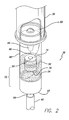
- FIG. 2 is a perspective view of certain details of the drip chamber 38 in which is located a magnetically-activated shut off valve in accordance with aspects of the invention.
- the drip chamber is mounted to the downstream end of a burette 36 for this application although this is not required.
- the drip chamber 38 may instead have a sharpened spike for directly accessing the bag 24 of medical fluid.
- Such configurations for drip chambers are common.
- the magnetic automatic shut off valve is located in a drip chamber.
- the magnetic valve could be used in other fluid containers or conduits as well.
- the drip chamber 38 includes a precise drop former 44 located at its upstream or proximal end operating to form drops 46 of a known size from the fluid in the burette 36 and permit those drops to fall into the transparent container 48 of the drip chamber 38.
- a float 50 is floating in the medical fluid 52 of the transparent container 48 due to its buoyancy. Downstream of the float 50 is a valve seat 54 in which the float will seat when the fluid 52 level lowers sufficiently.
- the float 50 and the valve seat 54 comprise a magnetic automatic shut off valve 55.
- the fluid level in the drip chamber 38 will vary depending on the amount of fluid remaining in the bag 24, in the upstream tubing 30, and in the burette 36 (see FIG. 1 ).
- the drip chamber also includes a downstream end 57 and defines an exit orifice 56 or outlet port at the downstream end to which the downstream tubing 40 is permanently attached in this embodiment. Also in this embodiment, the material used to form the transparent container 48 part of the drip chamber 38 is also used to form the exit orifice 56, although other arrangements may be used.
- fluid from the bag 24 has flowed through the upstream tubing 30 and into the burette 36 where it is accumulated to the desired level.
- the inlet to the burette is then closed and the fluid allowed to exit through the exit port 60 of the burette into the drop former 44 of the drip chamber 38.
- the drop former forms precisely-sized drops that may be counted and timed to verify that a desired flow rate has been established with a variable clamp or other means (not shown). Because the fluid level in the transparent container 48 is high, the float 50 is above the valve seat 54 and fluid flows out the drip chamber 38 through the exit orifice 56 and through the downstream tubing 40 into the patient 22 ( FIG. 1 ).
- FIG. 3 the elements of FIG. 2 are shown in cross-sectional form. More detail is also shown of the downstream end of the burette 36.
- the input end, or upstream end 58 of the drip chamber 38 is connected, in this embodiment, directly to the output, or downstream, end 60 of the burette 36.
- the hollow float 50 is shown suspended in the fluid 52 of the drip chamber above the valve seat 54 due to the relatively high level of the fluid level 52 and the buoyancy of the float.
- the float 50 as shown in cross-section, defines an internal elongate post 62 which, in a preferred embodiment, is co-axially aligned with the longitudinal axis 64 of the float and extends from one end 76 of the float to the opposing end 76.
- first magnetic attraction element 66 Positioned about the post is a first magnetic attraction element 66 adapted to slide freely along the length of the post.
- the first attraction element 66 has an annular form with the inner diameter of that annular form being larger in diameter than the outer diameter of the post and the outer diameter of that annular form having a size smaller in diameter than the inner diameter of the hollow float 50 so that the first attraction element may freely slide along the post within the float.
- the float 50 is configured to be buoyant, and to float in medical fluid with its longitudinal axis 64 oriented generally vertically.
- the float 50 is rotationally symmetrical about its longitudinal axis 64 and is symmetrical about a plane perpendicular to the longitudinal axis and passing through its transverse center line which is indicated by a line 68 in FIG. 3 . Because of this symmetry, the float may be initially assembled into the drip chamber with either end facing either direction. The internal first attraction element will simply fall to whichever end of the float is pointing down. This symmetry and freedom of the attraction element to move with gravity can lower manufacturing costs because fewer assembly errors will be made.
- a second magnetic attraction element 70 is positioned at the valve seat 54 to attract the float 50 into a seating, and fluid shut off, position in the valve seat.
- the second magnetic attraction element 70 is located adjacent the exit orifice 56 of the drip chamber 38 and in alignment with the first attraction element 66 of the float when the float is centered in the drip chamber.
- the second attraction element 70 also has an annular form.
- the sizes of the annular forms of the first 66 and second 70 magnetic attraction elements are identical or substantially identical so that the lines of magnetic flux generated by either or both magnetic attraction elements directly impinge upon the other magnetic attraction element to create the maximum attraction force.
- At least one of the first and second magnetic attraction elements 66 and 70 comprises a magnet while the other element is formed either of a magnetic material that is attracted by a magnetic field, such as ferrous metal or the like, or is also a magnet.
- the second magnetic attraction element 70 may be an annular magnet while the first magnetic attraction element 66 may be a washer-type device or flat ring, containing a ferrous metal.
- both the first and second magnetic attraction elements may be magnets.
- assembly of the float into the drip chamber during manufacture would require that it be oriented such that unlike magnetic poles of the first and second magnetic attraction elements 66 and 70 face each other so that the float is attracted, rather than repelled, by the second element 70.
- both the first and second magnetic elements 66 and 70 are physically isolated from any medical fluid that flows through the drip chamber 38. Such fluid does not come into contact with either element. This may be accomplished by coating the magnetic elements with parylene or other water resistant material, or by mounting the magnetic elements within fluid-tight container elements.
- the magnetic elements have been coated with parylene so that fluids are unable to reach the metallic surfaces of the magnetic elements.
- the first magnetic attraction element 66 is located about the post 62 within the float 50, and the float 50 is sealed so that it will remain buoyant.
- the transparent container 48 portion of the drip chamber 38 is relatively full of fluid 52 and the float 50 is buoyed to the fluid surface.
- the first attraction element 66 has fallen to the lower end of the post 62 in the float.
- the float has a length 51 and that the end of the float containing the first attraction element 66 is submerged with some volume of fluid 52 above it. Therefore when the submerged end of the float seats in the valve seat 54 shutting off flow, the fluid above its position at the valve seat will remain in the drip chamber. This is shown in FIG. 4 .
- the length 51 of the float ( FIG. 3 ) and its buoyancy have an effect on the amount of fluid remaining in the drip chamber when the magnetic automatic valve 55 shuts off and may be selected to result in a desired amount of fluid remaining.
- a similar effect is provided by the magnetic force developed by the first 66 and second 70 magnetic attraction elements.
- the stronger the force the sooner the float 50 will seat leaving more fluid remaining in the drip chamber than if the magnetic force were weaker.
- the strength of the magnetic force produced by the magnet may be selected so that the magnet will attract the float to the valve seat for shutting off flow when a selected level of fluid remains in the container.
- the strength of the magnetic force produced by the magnet may be selected so that the float will more readily align itself with the valve seat for automatic shutoff when the container is disposed at an angle other than vertical.
- the magnetic automatic shut off valve 55 will therefore be effective under a wider range of conditions of use of the drip chamber 38 than otherwise. For example, even in the case where the drip chamber is used during transport of the patient where the drip chamber may experience widely fluctuating tilt angles, the magnetic automatic shut off valve 55 will continue to function properly due to the strength of the magnetic attraction forces between the two magnetic parts 66 and 70 in the valve.
- the length 51 of the float 50 exceeds the inner diameter 53 of the transparent container 48 ( FIG. 4 ) of the drip chamber 38. Because of its length, the float is unable to rotate completely sideways in the drip chamber 38 and cannot wedge itself within the transparent container 48 thereby rendering the valve, of which it forms a part, inoperative. In more detail, the float 50 cannot rotate about the line 68 ( FIG. 3 ) through the center of the float (perpendicular to the longitudinal axis) at an angle of ninety degrees in the transparent chamber 48.
- the float 50 will move closer and closer to the second magnetic attraction element 70 until the point is reached where the force of magnetic attraction between the first and second attraction elements 66 and 70 is greater than the upward force on the float caused by its buoyancy. At this point, the float will move into the position shown in FIG. 4 to seal off the flow of the remaining fluid 52 from the drip chamber 38 through the exit orifice 56. Because the float seats and seals the drip chamber before the fluid in the chamber is depleted, it prevents the entry of air into the downstream tubing 40. A beneficial effect is that the drip chamber 38 and downstream tubing remain primed.
- the float in this embodiment includes two protruding portions 78 on opposing ends 76 that are rounded and each generally resembles a hemisphere.
- the float has rotational symmetry about a vertical axis 64 which in FIG. 5 , is coincident with the longitudinal axis 98 through the drip chamber 38.
- the float also includes a cylindrical center section 80 having a larger diameter than two cylindrical end sections 82 which are also cylindrical in this embodiment. Taper portions 84 interconnect the center section 80 with each of the end sections 82.
- a flat surface 86 surrounds each of the protruding portions and one or both form a sealing surface for interacting with the valve seat 54.
- the valve seat 54 includes a cylindrically-shaped base 88 that has an outer diameter just smaller than the inner diameter of the transparent container 48 so that it may be slid into place within the container. It may be held in place with adhesive, a snap fit, or other means, as will be discussed below in more detail. However, it should be noted that the base 88 must make enough contact with the transparent container 48 portion of the drip chamber 38 so that the fluid in the chamber cannot flow around the outside of the base between it and the drip chamber and out the exit orifice 56 to thereby compromise the valve 55.
- the base 88 is formed of a solid piece of material, such as silicone, and includes various relieved portions.
- a first relieved portion 90 is centered in the base 88 and has a diameter that is just equal to or smaller than the external diameter of the center section 80 of the float 50. It is deep enough to receive approximately one half of the length 51 of the float ( FIG. 3 ) when the float 50 and base 88 are axially aligned, and therefore forms a float-receiving first outlet conduit portion.
- a second relieved portion 92 is formed in the base at a location distal to the first relieved portion 90 and has dimensions large enough in this embodiment to receive the entire annular magnet 70, which is a second magnetically attractive element. It will be noted from FIG.
- first relieved portion 90 and second relieved portion 92 are both formed into the base 88 deeply enough so that a thin membrane 94 is left between them.
- a passage 96 is formed through the membrane 94 located between the first and second relieved portions so that fluid may flow between the first and second relieved portions and out the exit orifice 56 of the drip chamber.
- the combination of relieved portions 90 and 92 and the passage 96 through the first membrane 94 provides a fluid flow path out of the transparent container 48 portion of the drip chamber into the exit orifice 56 of the drip chamber.
- first relieved portion 90 and the second relieved portion 92 may be formed deeply enough into the base 88 so that they interconnect and no membrane is left between them. Instead, a separate membrane component is mounted within the larger first relieved portion 90 to provide a sealing surface for the float.
- This separate membrane component would be thin, as in the embodiment shown in FIG. 5 , and will function as does the membrane of FIG. 5 .
- This separate membrane component may be fixed in position by adhesive, as an example.
- the thickness of the membrane 94 is selected such that the membrane will provide an effective first sealing surface 97 that is oriented perpendicularly to the longitudinal center line 98 of the drip chamber 38 and will contact the flat surfaces 86 of the float ends 76 to form a fluid seal.
- the flat surfaces 86 of the float ends 76 are used to provide a second sealing surface to mate with the first sealing surface 97 of the valve seat and provide a first seal against fluid flowing out of the drip chamber.
- the base 88 includes a third relieved portion 100 concentric with the first relieved portion 90 and comprises a narrow cut into the wall of the base 88 at a position radially outward of the first relieved portion 90.
- the location of the third relieved portion is selected to leave a thin piece of material 102 in the form of a second membrane to provide a third sealing surface 101 that will contact the center portion 80 of the float when the float is seated in the valve seat 54.
- the enlarged cylindrical portion 80 of the float therefore provides a fourth sealing surface 103 to mate with the third sealing surface 101 of the base 88 to provide a second seal against fluid leaving the drip chamber once the float has been located in the seat 54.
- the effect of this second seal provided by the third 101 and fourth 103 sealing surfaces is shown in FIGS.
- the third sealing surface 101 is oriented in parallel with the longitudinal center line 98 of the drip chamber 38 and takes the form of a ring. It was found in one embodiment that the inner diameter of the first relieved portion 90 can be made to be slightly smaller than the outer diameter of the center section 80 of the float if the third relieved portion 100 is located such that the third sealing surface 101 is flexible enough to permit the float to properly seat. To obtain the necessary flexibility, the thickness of the second membrane 102 must be kept small and the narrow cut 100 must be deep enough so that the third sealing surface 101 will have the necessary flexibility to accommodate a slightly larger float 50. As shown in FIG. 5 , the cut 100 is deeper than the depth that the enlarged diameter center cylindrical section 80 of the float 50 extends into the valve seat 54. This configuration provides flexibility to the third sealing surface 101.
- the lower protruding portion 78 of the float extends through the opening 96 in the first membrane 94 when the float is properly situated in the valve seat 54. Because it is rounded, the protruding portion 78 assists in guiding the float into sealing contact with the first sealing surface 97 so that a fluid-tight seal is made. As shown, the first thin membrane 94 and its first sealing surface 97 overhangs the annular magnet 70 in a cantilever arrangement with the magnet providing support for this portion of the first sealing surface 96.
- the first sealing surface 97 also overhangs the opening of the annular magnet by a certain amount and it has been found that this unsupported portion of the sealing surface 97 flexes under contact with the sealing surface 86 of the end 76 of the float and provides a better seal with the second sealing surface 86.
- the ends 76 of the float 50 are formed of rigid thermoplastic polymer such as polypropylene and the first sealing membrane 94 is formed of flexible polymer such as thermoplastic elastomer or silicone. It has been found that these materials interact well to form an effective fluid seal.
- the thickness of the first sealing membrane 94 was 0.5 - 0.75 mm (0.02 - 0.03 inches).
- first and third described sealing surfaces 97 and 101 may produce a generally annular configuration, with one edge of the annulus of both connected to, or part of, respective areas of the base 88 and the other edge free to bend should the float 50 exert a force thereon while being magnetically drawn into contact with the base.
- first and third sealing surfaces By selecting appropriate thicknesses for the first and third sealing surfaces, the desired flexible contact and resulting seal between the transparent container 48 and the float 50 can be obtained.
- the first and third sealing surfaces described above may be formed of independent components introduced into the container in the form of membranes to be held by one-edge, and are not limited to forming part of a unitary component of any other portion of the stop-valve.
- the base 88 in this embodiment includes a locking ring 106 formed on the inner wall 108 of the transparent container 48.
- the locking ring is ramped towards the downstream direction but is perpendicular to the wall 108 in the upstream direction.
- the base 88 and magnet 70 combination may be slid into the transparent container 48 and over the locking ring during assembly and will be held in position as shown in FIG. 5 by the locking ring.
- FIG. 5 also shows that the second sealing membrane 102 is located at a more distal position than the more radially outward portion of the base 88, which would permit the inclusion of a taper 110 leading to the second sealing lip 102.
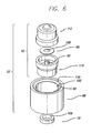
- the float 50 comprises first and second identical float portions 112 and 114 or halves, each of which has one-half the inner post 62.
- the first attractive element 66 which in this case is a washer formed of magnetically attractive material, is mounted on one of the post halves.
- the two float portions may then be permanently assembled together such as by adhesive, or ultrasonic welding, or with other means such as spin welding.
- FIG. 6 further shows an embodiment of a base 88 having a first relieved portion 90, a third relieved portion 100, and a taper 110 from the outer wall to the third relieved portion.
- the second attractive element 70 is shown, which in this case is a magnet, and although the second relieved portion of the base is not shown in this view, it is identical to that shown in FIG. 5 .
- the magnet 70 would therefore slide up and into the distal end, or downstream end, of the base into the second relieved portion (92 shown in FIG. 5 ).
- the outer diameter of the magnet 70 is identical or substantially the same as the outer diameter of the washer 66, and when the float is properly seated in the valve seat as shown in FIG.
- the washer 66 and magnet 70 will be aligned with each other. Additionally, the aperture 108 of the washer and the aperture 109 of the magnet will also be aligned with each other and in this embodiment, have approximately the same diameter. This matching of physical characteristics and alignment will result in the more efficient use of the magnetic attraction force provided by the magnet 70, so that a smaller magnet can be used with commensurate lower manufacturing costs.
- operation of the magnetic automatic shut off valve 55 may commence with the fluid container 24 being accessed and the administration set 34 primed. A selected amount of fluid is allowed to flow into the burette 36. The burette is then closed and fluid permitted to flow from the burette output port 60 into the drip chamber 38. The float is dislodged from the valve seat 54 by mechanical means, such as by squeezing the side of the transparent container 48 at the valve seat thereby overcoming the magnetic force holding it in a sealed position in the seat 54. The float will then rise with the fluid level in the drip chamber opening the exit orifice 56 so that fluid may flow to the patient 22.
- the fluid level in the drip chamber 38 will become depleted and the magnetic force between the first and second magnetic attraction elements 66 and 70 will cause the float to seal off the exit orifice 56 of the drip chamber and flow through the fluid administration set 34 will cease. Because the length 51 of the float 50 exceeds the inner diameter 53 of the drip chamber, it will not become wedged in the transparent container 48 of the drip chamber even if the drip chamber is not level or is being moved due to patient activity or transport. Additionally, the float will be strongly attracted into proper alignment with the first relieved portion 90 of the valve seat 54 due to the magnetic force developed by the centrally-located magnet 70.
- the tapered sections 86 between the cylindrical sections of the float would act as guides to re-orient the float into a correct alignment with the first relieved portion 90 of the valve seat upon meeting the taper 110 of the wall (see FIG. 5 ).
- the float has beveled or rounded edges to assist in properly locating it in the valve seat. The prime in the fluid administration set is preserved and this feature of the stop-valve 55 will allow the burette to be refilled with fluid and an infusion to begin again without having to re-prime the set 34.
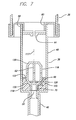
- the float 116 continues to be rotationally symmetrical about its longitudinal axis 117 to aid in manufacturing and assembling the drip chamber, and continues to comprise an internal post 62 on which the first magnetic element 66 is slidably mounted.
- the drip chamber 38 also comprises a valve seat 118 formed of a base 120; however, in this embodiment, the base 120 differs from the base shown in FIG. 5 .
- the base 120 comprises a first relieved portion 122 that is angled in this case.
- a second relieved portion 124 is provided as in the previous embodiment and once again connects with the exit orifice 56. However, the first and second relieved portions are interconnected with no membrane in between.
- the second magnetically attractive element 70 is located in the second relieved portion 124 as in the previous embodiment.
- the first relieved portion 124 at the upstream end of the base 120 has a different configuration from the base of FIG. 5 .
- the first relieved portion is tapered at an approximate angle (shown as "A" in FIG. 7 ) of 70 degrees providing a first sealing surface 126 opening into a passage 128 through the base that connects the transparent container 48 with the exit orifice 56 to allow fluid flow out of the drip chamber 38.
- the float 116 also includes a tapered sealing surface 130 forming a second sealing surface that is complementary to the taper and sealing surface 126 of the valve seat 118.
- the tapered sealing surface 130 of the float has a frusto-conical shape.
- the end tips 132 of the float 116 are shown flat but may have other shapes, such as round or pointed.
- the sealing surface shapes 124 and 130 of the embodiment of FIG. 7 have an advantage in that they provide a larger overall sealing surface area and a membrane or membranes such as that shown in FIG. 5 are not needed.
- a valve seat 154 seal and retaining arrangement comprising inward protrusions 156 from the inner wall 158 of the drip chamber with selectively located grooves 160 formed in the outer surface 162 of the valve seat 154.
- a first distal groove 164 is formed in the valve seat that coincides with a first protrusion 166 on the inner wall of the drip chamber.
- This, and a second groove 168 on the valve seat and a second protrusion 170 on the wall 158 serve to engage two protrusions from the drip chamber wall and retain the valve seat 154 in the desired position in the drip chamber.
- the protrusions from the drip chamber wall take the form of rings in this embodiment.
- the grooves of the valve seat are also formed completely around the valve seat so that ease in manufacturing results. More or fewer protrusions and grooves may be used in other embodiments.
- a third groove 172 formed at the proximal end of the valve seat leaves a raised ring 174 on the valve seat that will contact the inner wall 158 of the drip chamber and form a fluid seal 176.
- This fluid seal 176 will prevent fluid from flowing around the outside of the valve seat and out the outlet port 56.
- FIG. 9 presents an external perspective view of only the valve seat 154 of FIG. 8 showing the grooves and first relieved portion 90.
- FIG. 10 shows in an exaggerated way the taper of the drip chamber 152. The angle of taper is indicated by numeral 190. The taper not only aids in molding the drip chamber but also aids in inserting the valve seat 154.
Landscapes
- Engineering & Computer Science (AREA)
- Health & Medical Sciences (AREA)
- General Engineering & Computer Science (AREA)
- Mechanical Engineering (AREA)
- Life Sciences & Earth Sciences (AREA)
- Public Health (AREA)
- Heart & Thoracic Surgery (AREA)
- Hematology (AREA)
- Anesthesiology (AREA)
- Animal Behavior & Ethology (AREA)
- General Health & Medical Sciences (AREA)
- Biomedical Technology (AREA)
- Veterinary Medicine (AREA)
- Vascular Medicine (AREA)
- Emergency Medicine (AREA)
- Infusion, Injection, And Reservoir Apparatuses (AREA)
- Magnetically Actuated Valves (AREA)
- External Artificial Organs (AREA)
Claims (25)
- Automatisches Abschlussventil für den Gebrauch in der Regelung des Flusses eines medizinischen Fluids, umfassend:einen Behälter (48), der geeignet ist ein medizinisches Fluid zu enthalten, wobei der Behälter besitzt ein stromauf gelegenes Ende und ein stromab gelegenes Ende und eine Ausgangsöffnung (56) am stromab gelegenen Ende;einen Hohlschwimmer (50), der im Behälter (48) angeordnet ist;ein erstes anziehendes Element (66), das im Schwimmer (50) angeordnet ist; undein zweites anziehendes Element (70), das angeordnet ist bei der Ausgangsöffnung (56), wobei das erste und das zweite anziehende Element (66, 70) gebildet sind aus Materialien, die erzeugen eine magnetische Anziehung zwischen den beiden Elementen (66, 70);wobei die Materialien, welche die magnetische Anziehung erzeugen zwischen den beiden Elementen (66, 70), ausgewählt sind, sodass die Stärke der magnetischen Anziehung zwischen den beiden Elementen (66, 70) so ist, dass, wenn das Fluid im Behälter (48) auf eine Höhe nahe der Entleerung fällt, das erste und das zweite anziehende Element (66, 70) sich gegenseitig anziehen mit einer Kraft, die groß genug ist, dass der Schwimmer (50) bewegt wird in eine Position, in der das stromab gelegene Ende für den Fluidfluss verschlossen ist;
gekennzeichnet dadurch, dass der Hohlschwimmer (50) einen inneren Stab (62) begrenzt, wobei das erste anziehende Element (66) angeordnet ist um den Stab (62) und geeignet ist entlang des Stabs (62) zu gleiten. - Automatisches Abschlussventil nach Anspruch 1, weiterhin umfassend:einen Ventilsitz (54), der angeordnet ist nahe bei der Ausgangsöffnung (56) am stromab gelegenen Ende des Behälters (48), wobei der Ventilsitz (54) besitzt eine erste Dichtfläche (97);wobei der Schwimmer (50) umfasst eine zweite Dichtfläche (86), die ausgelegt ist sich mit der ersten Dichtfläche (97) zu verbinden und eine Dichtung gegen den Fluidfluss zu bilden.
- Automatisches Abschlussventil nach Anspruch 2, weiterhin umfassend:eine dritte Dichtfläche (101), die angeordnet ist in einer festen Position im Behälter (48) an einer ausgewählten Stelle entfernt von der ersten Dichtfläche (97); undeine vierte Dichtfläche (103), die angeordnet ist auf dem Schwimmer (50) und ausgelegt ist sich mit der dritten Dichtfläche (101) zu verbinden für die Bereitstellung einer besseren Dichtung gegen den Fluidfluss.
- Automatisches Abschlussventil nach Anspruch 3, wobei der Schwimmer (50) besitzt einen Bereich mit vergrößertem Durchmesser, der die vierte Dichtfläche (103) bildet.
- Automatisches Abschlussventil nach Anspruch 4, wobei der Bereich mit vergrößertem Durchmesser, der die vierte Dichtfläche (103) bildet, sich im Wesentlichen in der Mitte des Schwimmers (50) befindet.
- Automatisches Abschlussventil nach Anspruch 3, wobei die dritte Dichtfläche (101) umfasst eine Membran aus biegsamem Material, die im Wesentlichen ringförmig ist und besitzt einen Innendurchmesser, der kleiner ist als der Außendurchmesser der vierten Dichtfläche (103) des Schwimmers (50), wobei die dritte Dichtfläche (101) und die vierte Dichtfläche (103) miteinander in Berührung kommen und dadurch den Fluidfluss abdichten, wenn der Schwimmer (50) angeordnet ist, sodass die erste und die zweite Dichtfläche (97, 86) in Berührung sind.
- Automatisches Abschlussventil nach Anspruch 1, weiterhin umfassend:eine erste Dichtfläche (97), die angeordnet ist in einer festen Position im Behälter (48) nahe bei der Ausgangsöffnung (56) am stromab gelegenen Ende des Behälters (48); undeine dritte Dichtfläche (101), die angeordnet ist in einer festen Position im Behälter (48) an der Behälterwand an einer ausgewählten Stelle entfernt von der ersten Dichtfläche (97);wobei die erste und die dritte Dichtfläche (97, 101) dazu führen, dass der Schwimmer (50) eine Dichtung gegen den Fluidfluss bildet, wenn der Schwimmer (50) bewegt wird in die Position, die das stromab gelegene Ende abdichtet gegen den Fluidfluss durch die magnetische Anziehung zwischen den beiden Elementen (66, 70).
- Automatisches Abschlussventil nach Anspruch 7, wobei:der Schwimmer (50) umfasst gegenüberliegende Enden (76), wobei jedes Ende (76) enthält eine zweite Dichtfläche (86), die ausgelegt ist sich mit der ersten Dichtfläche (97) zu verbinden; undder Schwimmer (50) umfasst einen hauptsächlich zylindrischen Bereich, der bereitstellt eine vierte Dichtfläche (103), die ausgelegt ist sich mit der dritten Dichtfläche (101) zu verbinden;wobei die erste und die zweite Dichtfläche (97, 86) bilden eine Dichtung gegen den Fluss und die dritte und die vierte Dichtfläche (101, 103) bilden eine andere Dichtung gegen den Fluss, wenn der Schwimmer (50) bewegt ist in die Position, in der das stromab gelegene Ende abgedichtet ist gegen den Fluidfluss durch die magnetische Anziehung zwischen den beiden Elementen (66, 70).
- Automatisches Abschlussventil nach Anspruch 1, 7 oder 8, wobei der Schwimmer (50) umfasst zwei im Wesentlichen identische Hälften (82), die verbunden sind und den Schwimmer (50) bilden, wobei jede Hälfte (82) des Schwimmers umfasst eine Hälfte des Stabs (62), sodass, wenn die im Wesentlichen identischen Hälften (82) des Schwimmers verbunden sind, der gesamte innere Stab (62) ausgebildet ist.
- Automatisches Abschlussventil nach Anspruch 9, wobei:der Schwimmer (50) hauptsächlich zylindrisch ist mit einem zylindrischen Bereich mit größerem Durchmesser, der sich befindet in der Längsrichtung in der Mitte des Schwimmers (50);der Schwimmer (50) umfasst gegenüberliegende Enden (76); unddas erste anziehende Element (66) angeordnet ist um den Stab (62), sodass es frei gleiten kann entlang des Stabs (62);wobei man den Schwimmer (50) einsetzen kann in den Behälter (48) mit irgendeinem der beiden gegenüberliegenden Enden (76) zugewandt der Ausgangsöffnung (56) am stromab gelegenen Ende des Behälters (48) und das erste anziehende Element (66) gleitet entlang der inneren Stabs (62) in Richtung des zweiten anziehenden Elements (70) für das Aufstellen einer magnetischen Wechselwirkung mit dem zweiten anziehenden Element (70).
- Automatisches Abschlussventil nach Anspruch 10, wobei:das erste anziehende Element (66) besitzt eine innere Öffnung mit einem Durchmesser, der größer ist als der Durchmesser des Stabs (62); undder Außendurchmesser des ersten anziehenden Elements (66) kleiner ist als der Innendurchmesser des Hohlschwimmers (50);wobei das erste anziehende Element (66) frei entlang des Stabs (62) im Schwimmer (50) gleiten kann.
- Automatisches Abschlussventil nach Anspruch 1, wobei der Schwimmer (50) besitzt eine Länge, die größer ist als der Innendurchmesser des Behälters (48).
- Automatisches Abschlussventil nach Anspruch 1, wobei mindestens eines der ersten und zweiten anziehenden Elemente (66, 70) umfasst einen Magneten mit einer durch den Magneten erzeugten Magnetstärke, die gewählt ist, sodass der Magnet den Schwimmer (50) zum Ventilsitz (54) anzieht für das Sperren des Flusses, wenn eine gewählte Höhe des Fluids im Behälter (48) übrig ist.
- Automatisches Abschlussventil nach Anspruch 13, wobei die durch den Magneten erzeugte Magnetstärke gewählt ist, sodass der Schwimmer (50) sich mit dem Ventilsitz (54) ausrichtet, wenn der Behälter (48) angeordnet ist in einem anderen Winkel als senkrecht.
- Automatisches Abschlussventil nach Anspruch 1 oder 10, wobei mindestens eines der ersten und zweiten anziehenden Elemente (66, 70) umfasst einen Magneten mit einer durch den Magneten erzeugten Magnetstärke, die gewählt ist, sodass der Schwimmer (50) sich mit dem Ventilsitz (54) ausrichtet, wenn der Behälter (48) angeordnet ist in einem anderen Winkel als senkrecht.
- Automatisches Abschlussventil nach Anspruch 1 oder 10, wobei der Schwimmer (50) eine Längsachse besitzt und rotationssymmetrisch um die Längsachse ist.
- Automatisches Abschlussventil nach Anspruch 1 oder 10, wobei der Schwimmer (50) symmetrisch ist bezüglich einer Ebene senkrecht auf der Längsachse des Schwimmers, wobei die Ebene den Schwimmer (50) in der Mitte schneidet.
- Verfahren für das automatische Sperren des Flusses eines medizinischen Fluids aus einem Behälter (48), der besitzt ein stromauf gelegenes Ende und ein stromab gelegenes Ende und eine Ausgangsöffnung (56) am stromab gelegenen Ende, wobei das Verfahren umfasst:Anordnen eines ersten anziehenden Elements (66) in einem Hohlschwimmer (50);Anordnen eines zweiten anziehenden Elements (70) bei der Ausgangsöffnung (56), wobei das erste anziehende Element (66) und das zweite anziehende Element (70) gebildet sind aus Materialien, die erzeugen eine magnetische Anziehung zwischen den beiden Elementen (66, 70); undEinsetzen des Schwimmers (50) in den Behälter (48), sodass, wenn das Fluid im Behälter (48) auf eine Höhe nahe der Entleerung fällt, das erste und das zweite anziehende Element (66, 70) sich gegenseitig anziehen mit einer Kraft, die groß genug ist, dass der Schwimmer (50) bewegt wird in eine Position, in der das stromab gelegene Ende für den Fluidfluss verschlossen ist;gekennzeichnet durch das Anordnen des ersten anziehenden Elements (66) um einen Stab (62), der angeordnet ist im Schwimmer (50), sodass das erste anziehende Element (66) frei entlang des Stabs (62) gleiten kann.
- Verfahren für das automatische Sperren des Flusses eines medizinischen Fluids nach Anspruch 18, weiterhin umfassend:Bilden des Schwimmers (50) aus zwei verbundenen, im Wesentlichen identischen Hälften (82), wobei jede der Schwimmerhälften (82) umfasst eine Hälfte des Stabs (62), sodass, wenn die im Wesentlichen identischen Schwimmerhälften (82) verbunden werden, der gesamte Stab (62) ausgebildet ist.
- Verfahren für das automatische Sperren des Flusses eines medizinischen Fluids nach Anspruch 18, weiterhin umfassend:Bilden des Schwimmers (50), sodass er hauptsächlich zylindrisch ist mit einem zylindrischen Bereich mit großem Durchmesser in Längsrichtung in der Mitte und sodass der Schwimmer (50) gegenüberliegende Enden (76) besitzt; undAnordnen des ersten anziehenden Elements (66) um den Stab (62), sodass das erste anziehende Element (66) frei entlang des Stabs (62) gleiten kann;wobei man den Schwimmer (50) einsetzen kann in den Behälter (48) mit irgendeinem der beiden gegenüberliegenden Enden (76) zugewandt der Ausgangsöffnung (56) am stromab gelegenen Ende des Behälters (48) und das erste anziehende Element (66) gleitet entlang der inneren Stabs (62) in Richtung des zweiten anziehenden Elements (70) für das Aufstellen einer magnetischen Wechselwirkung mit dem zweiten anziehenden Element (70).
- Verfahren für das automatische Sperren des Flusses eines medizinischen Fluids nach Anspruch 18, weiterhin umfassend:Bilden des Schwimmers (50) mit einer Länge, die größer ist als der Innendurchmesser des Behälters (48).
- Verfahren für das automatische Sperren des Flusses eines medizinischen Fluids nach Anspruch 18, weiterhin umfassend:Bilden des ersten und des zweiten anziehenden Elements (66, 70), sodass mindestens eines einen Magneten umfasst; undWählen der durch den Magneten erzeugten Magnetstärke, sodass der Magnet den Schwimmer (50) zum Ventilsitz (54) anzieht für das Sperren des Flusses, wenn eine gewählte Höhe des Fluids im Behälter (48) übrig ist.
- Verfahren für das automatische Sperren des Flusses eines medizinischen Fluids nach Anspruch 22, weiterhin umfassend:Wählen der durch den Magneten erzeugten Magnetstärke, sodass der Schwimmer (50) sich mit dem Ventilsitz (54) ausrichtet, wenn der Behälter (48) angeordnet ist in einem anderen Winkel als senkrecht.
- Verfahren für das automatische Sperren des Flusses eines medizinischen Fluids nach Anspruch 18, weiterhin umfassend:Bilden des Schwimmers (50), sodass er rotationssymmetrisch um die Längsachse ist.
- Verfahren für das automatische Sperren des Flusses eines medizinischen Fluids nach Anspruch 18, weiterhin umfassend:Bilden des Schwimmers (50), sodass er symmetrisch ist bezüglich einer Ebene senkrecht auf der Längsachse des Schwimmers, wobei die Ebene den Schwimmer (50) in der Mitte schneidet
Applications Claiming Priority (3)
| Application Number | Priority Date | Filing Date | Title |
|---|---|---|---|
| US321249 | 1989-03-09 | ||
| US10/321,249 US6695004B1 (en) | 2002-12-16 | 2002-12-16 | Magnetic automatic stop valve |
| PCT/US2003/038639 WO2004060457A1 (en) | 2002-12-16 | 2003-12-03 | Magnetic automatic stop valve |
Publications (2)
| Publication Number | Publication Date |
|---|---|
| EP1575647A1 EP1575647A1 (de) | 2005-09-21 |
| EP1575647B1 true EP1575647B1 (de) | 2008-08-20 |
Family
ID=31495572
Family Applications (1)
| Application Number | Title | Priority Date | Filing Date |
|---|---|---|---|
| EP03787268A Expired - Lifetime EP1575647B1 (de) | 2002-12-16 | 2003-12-03 | Magnetisches automatisches absperrventil |
Country Status (12)
| Country | Link |
|---|---|
| US (1) | US6695004B1 (de) |
| EP (1) | EP1575647B1 (de) |
| JP (1) | JP2006509599A (de) |
| AT (1) | ATE405311T1 (de) |
| AU (1) | AU2003294580B2 (de) |
| CA (1) | CA2510065C (de) |
| DE (1) | DE60323146D1 (de) |
| DK (1) | DK1575647T3 (de) |
| ES (1) | ES2312840T3 (de) |
| NZ (1) | NZ540914A (de) |
| PT (1) | PT1575647E (de) |
| WO (1) | WO2004060457A1 (de) |
Cited By (1)
| Publication number | Priority date | Publication date | Assignee | Title |
|---|---|---|---|---|
| EP3813900A4 (de) * | 2018-06-29 | 2022-05-04 | 410 Medical, Inc. | Systeme, vorrichtung und verfahren zum filtern von luft aus einer fluidleitung |
Families Citing this family (48)
| Publication number | Priority date | Publication date | Assignee | Title |
|---|---|---|---|---|
| US7722577B2 (en) * | 2005-02-18 | 2010-05-25 | Becton, Dickinson And Company | Bubble free—self primed IV set |
| US20060206049A1 (en) * | 2005-03-14 | 2006-09-14 | Rodgers M S | MEMS flow module with piston-type pressure regulating structure |
| US7879014B2 (en) * | 2004-12-09 | 2011-02-01 | Merit Medical Systems, Inc. | Valve assembly with chamber vent and fluid deflector |
| US7731699B2 (en) * | 2004-12-09 | 2010-06-08 | Merit Medical Systems, Inc. | Burette float and drainage aperture |
| US7338475B2 (en) * | 2004-12-17 | 2008-03-04 | Cardinal Health 303, Inc. | Electret enhanced automatic IV drip chamber shutoff |
| WO2007108646A1 (en) * | 2006-05-24 | 2007-09-27 | Seung-Hwan Heo | Device for protecting backward flowing in infusion solution delivering set |
| US8221366B2 (en) | 2007-09-05 | 2012-07-17 | Integra Lifesciences Corporation | Volume limiting bodily fluid drainage system |
| CA2749771C (en) * | 2008-01-28 | 2018-05-01 | Milux Holding S.A. | A drainage device comprising an active filter |
| US8568368B2 (en) * | 2008-04-14 | 2013-10-29 | Merit Medical Systems, Inc. | Contrast media diffusion system |
| US8353864B2 (en) * | 2009-02-18 | 2013-01-15 | Davis David L | Low cost disposable infusion pump |
| US20100211002A1 (en) * | 2009-02-18 | 2010-08-19 | Davis David L | Electromagnetic infusion pump with integral flow monitor |
| US8197235B2 (en) * | 2009-02-18 | 2012-06-12 | Davis David L | Infusion pump with integrated permanent magnet |
| BRPI1013332B8 (pt) * | 2009-04-29 | 2021-06-22 | Poly Medicure Ltd | conjunto intravenoso com um mecanismo de obtenção automática na câmara de gotejamento |
| KR101182419B1 (ko) | 2009-10-27 | 2012-09-12 | 박우철 | 무동력 정량투입 장치 |
| BR112012010287A2 (pt) * | 2009-11-25 | 2016-03-29 | Baxter Healthcare Sa | sistema de controle de fluxo, e, método para regular o fluxo de fluido através de uma câmera de gotejamento |
| MY164744A (en) * | 2010-10-29 | 2018-01-30 | Hian Khim Francis Then | Intravenous fluid delivery system |
| FR2967955B1 (fr) * | 2010-11-29 | 2012-12-14 | Peugeot Citroen Automobiles Sa | Circuit de distribution de liquide lave-glace pour vehicule automobile. |
| US8460253B2 (en) * | 2011-01-03 | 2013-06-11 | Manuel Dugrot | Magnetically sealed intravenous access valve |
| JP2014515694A (ja) | 2011-03-11 | 2014-07-03 | ギーシェン ヤン、 | 磁性粒子スカベンジング装置および方法 |
| US8858513B2 (en) * | 2011-05-16 | 2014-10-14 | Dragon Heart Medical Devices Co., Ltd. | Disposable intravenous flow control device |
| WO2013041916A1 (en) * | 2011-09-20 | 2013-03-28 | Wickramasinghe Nileththi Janaka | A drip set |
| US8535241B2 (en) | 2011-10-13 | 2013-09-17 | Magnolia Medical Technologies, Inc. | Fluid diversion mechanism for bodily-fluid sampling |
| ES2656637T3 (es) * | 2012-02-28 | 2018-02-27 | Ge Healthcare As | Vial con válvula de flotador libre para productos farmacéuticos estériles |
| US9060724B2 (en) | 2012-05-30 | 2015-06-23 | Magnolia Medical Technologies, Inc. | Fluid diversion mechanism for bodily-fluid sampling |
| US9022951B2 (en) | 2012-05-30 | 2015-05-05 | Magnolia Medical Technologies, Inc. | Fluid diversion mechanism for bodily-fluid sampling |
| WO2014022275A1 (en) | 2012-08-01 | 2014-02-06 | Magnolia Medical Technologies, Inc. | Fluid diversion mechanism for bodily-fluid sampling |
| EP3906952A1 (de) | 2012-10-11 | 2021-11-10 | Magnolia Medical Technologies, Inc. | Systeme und verfahren zur abgabe einer flüssigkeit an einen patienten mit reduzierter kontamination |
| CA2931983C (en) | 2012-11-30 | 2021-12-07 | Magnolia Medical Technologies, Inc. | Syringe based fluid diversion mechanism for bodily-fluid sampling |
| IL303591B2 (en) | 2012-12-04 | 2025-11-01 | Magnolia Medical Technologies Inc | Sterile bodily-fluid collection device and methods |
| US10772548B2 (en) | 2012-12-04 | 2020-09-15 | Magnolia Medical Technologies, Inc. | Sterile bodily-fluid collection device and methods |
| CN104707222A (zh) * | 2013-12-14 | 2015-06-17 | 广东龙心医疗器械有限公司 | 一次性使用止液输液器 |
| EP3769681B1 (de) | 2015-06-12 | 2022-03-02 | Magnolia Medical Technologies, Inc. | Vorrichtung zur probenahme und fluidtransfer von körperflüssigkeiten |
| US10010282B2 (en) | 2015-07-24 | 2018-07-03 | Kurin, Inc. | Blood sample optimization system and blood contaminant sequestration device and method |
| EP3344213B1 (de) | 2015-09-03 | 2020-04-22 | Magnolia Medical Technologies, Inc. | System zum aufrechterhalten der sterilität eines probenbehälters |
| ITUB20160113A1 (it) * | 2016-02-05 | 2017-08-05 | Borla Ind | Valvola di fondo per camere di gocciolamento di apparecchiature medicali di infusione o trasfusione |
| US10827964B2 (en) | 2017-02-10 | 2020-11-10 | Kurin, Inc. | Blood contaminant sequestration device with one-way air valve and air-permeable blood barrier with closure mechanism |
| US20180353117A1 (en) | 2017-06-09 | 2018-12-13 | Magnolia Medical Technologies, Inc. | Fluid control devices and methods of using the same |
| CN116250868A (zh) | 2017-09-12 | 2023-06-13 | 木兰医药技术股份有限公司 | 流体控制装置及其使用方法 |
| CN107596492A (zh) * | 2017-09-29 | 2018-01-19 | 陈芳 | 一种输液器防回流装置 |
| CN115553822A (zh) | 2017-12-07 | 2023-01-03 | 木兰医药技术股份有限公司 | 流体控制装置及其使用方法 |
| RU183869U1 (ru) * | 2017-12-28 | 2018-10-05 | Дмитрий Петрович Миногин | Устройство для вливания инфузионных растворов с ручным нагнетателем |
| US11278915B1 (en) | 2018-07-20 | 2022-03-22 | NeoGeneStar LLC | Device for capturing and releasing magnetic particles |
| US11786155B2 (en) | 2019-02-08 | 2023-10-17 | Magnolia Medical Technologies, Inc. | Devices and methods for bodily fluid collection and distribution |
| CN113784793B (zh) | 2019-03-11 | 2023-09-19 | 木兰医药技术股份有限公司 | 流体控制装置及其使用方法 |
| IL322058A (en) | 2019-04-01 | 2025-09-01 | Kurin Inc | Device and system for optimizing sampling of non-aerated liquids |
| US20220226569A1 (en) * | 2021-01-19 | 2022-07-21 | Chs Healthcare Ventures, Inc. | Method and Manufacture of a dual lumen fiber optic medical infusion line |
| US20240410479A1 (en) * | 2023-06-06 | 2024-12-12 | Jordan Travis Ortiz | Self-Closing Device |
| US12466595B2 (en) * | 2024-02-06 | 2025-11-11 | Universal Trim Supply Co., Ltd. | Vacuum kit adapted for a container and related vacuum product |
Family Cites Families (28)
| Publication number | Priority date | Publication date | Assignee | Title |
|---|---|---|---|---|
| USRE26124E (en) | 1966-12-13 | Injection set and flow meter for parenteral fluids | ||
| US2538662A (en) | 1950-01-24 | 1951-01-16 | Charles C Abbott | Expendable valve unit for surgical appliances |
| US2691386A (en) | 1951-04-06 | 1954-10-12 | June L Madison | Fluid level safety control valve |
| US2879784A (en) | 1954-03-08 | 1959-03-31 | Cutter Lab | Check valve for the administration of parenteral solutions |
| US2784733A (en) * | 1954-10-08 | 1957-03-12 | Baxter Don Inc | Check valve for parenteral solutions |
| FR1215750A (fr) * | 1958-11-13 | 1960-04-20 | Ampoule de contrôle pour injection hypodermique et intraveineuse du type goutte à goutte | |
| US3105511A (en) | 1961-08-10 | 1963-10-01 | Cordis Corp | Infusion safety valve |
| US3207372A (en) * | 1962-09-21 | 1965-09-21 | Sterilon Corp | Intravenous feeding apparatus |
| US3233625A (en) | 1963-11-22 | 1966-02-08 | Houston Company | Magnetically operated valve |
| US3467135A (en) | 1965-07-23 | 1969-09-16 | Ulrich Gunther Muskalla | Magnetic float valve |
| SE358556B (de) * | 1969-04-07 | 1973-08-06 | Medizin Labortechnik Veb K | |
| US3989043A (en) | 1974-12-23 | 1976-11-02 | John Dimeff | Automatic flow control and automatic shut off for intravenous feeders |
| US3980457A (en) * | 1975-02-18 | 1976-09-14 | International Basic Economy Corporation | Pneumatic filter/separator with magnetically controlled fluid valve |
| DE2720522C3 (de) * | 1977-05-06 | 1980-02-07 | Yarden Medical Engineering Ltd., Haifa (Israel) | Vorrichtung zur Einstellung des Durchflusses einer Flüssigkeit |
| US4175558A (en) * | 1977-07-15 | 1979-11-27 | Baxter Travenol Laboratories, Inc. | Apparatus for administering parenteral liquid in sequential units provided with a ball valve float |
| DE2839774A1 (de) * | 1978-09-13 | 1980-03-27 | Yoram Prof Dr Med Palti | Vorrichtung zur einstellung des durchflussquerschnitts eines ventils |
| US4562855A (en) * | 1981-09-08 | 1986-01-07 | Cummings Ernie W | Automatic drain valve |
| US4769007A (en) * | 1987-03-25 | 1988-09-06 | Hsu Shun Fa | Automatic shutting-off sealing and alarming device for dripping injection use |
| IL89272A (en) * | 1988-02-29 | 1991-09-16 | Dedalos Costa Kypris | Automatic irrigation regulator controlled by water evaporation |
| US5014735A (en) * | 1990-05-02 | 1991-05-14 | Drain-All, Inc. | Automatic drain valve |
| US5176167A (en) * | 1992-05-08 | 1993-01-05 | Tiao Su Hua | Control valve |
| US5527295A (en) | 1995-02-22 | 1996-06-18 | Wing; Michael L. | Gravitational, magnetic, floating ball valve |
| US5655568A (en) * | 1995-08-08 | 1997-08-12 | Bhargava; Raj | Passive flow regulating device |
| US5730730A (en) * | 1995-09-29 | 1998-03-24 | Darling, Jr.; Phillip H. | Liquid flow rate control device |
| US6213986B1 (en) | 1995-09-29 | 2001-04-10 | Appro Healthcare, Inc. | Liquid flow rate control device |
| US6019114A (en) * | 1997-02-12 | 2000-02-01 | Icon Dynaamics, Llc | Self-metering reservoir |
| US5983919A (en) * | 1998-09-24 | 1999-11-16 | Drain-All, Inc. | Automatic drain valve |
| US6619341B2 (en) * | 2002-02-08 | 2003-09-16 | George Cushing | Pouring spout with automatic shut-off for portable fuel containers |
-
2002
- 2002-12-16 US US10/321,249 patent/US6695004B1/en not_active Expired - Lifetime
-
2003
- 2003-12-03 EP EP03787268A patent/EP1575647B1/de not_active Expired - Lifetime
- 2003-12-03 CA CA 2510065 patent/CA2510065C/en not_active Expired - Fee Related
- 2003-12-03 DE DE60323146T patent/DE60323146D1/de not_active Expired - Lifetime
- 2003-12-03 NZ NZ540914A patent/NZ540914A/en not_active IP Right Cessation
- 2003-12-03 AU AU2003294580A patent/AU2003294580B2/en not_active Ceased
- 2003-12-03 ES ES03787268T patent/ES2312840T3/es not_active Expired - Lifetime
- 2003-12-03 DK DK03787268T patent/DK1575647T3/da active
- 2003-12-03 PT PT03787268T patent/PT1575647E/pt unknown
- 2003-12-03 WO PCT/US2003/038639 patent/WO2004060457A1/en not_active Ceased
- 2003-12-03 JP JP2004565212A patent/JP2006509599A/ja active Pending
- 2003-12-03 AT AT03787268T patent/ATE405311T1/de not_active IP Right Cessation
Cited By (2)
| Publication number | Priority date | Publication date | Assignee | Title |
|---|---|---|---|---|
| EP3813900A4 (de) * | 2018-06-29 | 2022-05-04 | 410 Medical, Inc. | Systeme, vorrichtung und verfahren zum filtern von luft aus einer fluidleitung |
| US12440629B2 (en) | 2018-06-29 | 2025-10-14 | 410 Medical, Inc. | Systems, apparatus, and methods for filtering air from a fluid line |
Also Published As
| Publication number | Publication date |
|---|---|
| EP1575647A1 (de) | 2005-09-21 |
| PT1575647E (pt) | 2008-11-24 |
| US6695004B1 (en) | 2004-02-24 |
| NZ540914A (en) | 2008-02-29 |
| CA2510065A1 (en) | 2004-07-22 |
| CA2510065C (en) | 2011-05-24 |
| ES2312840T3 (es) | 2009-03-01 |
| ATE405311T1 (de) | 2008-09-15 |
| AU2003294580B2 (en) | 2008-07-17 |
| JP2006509599A (ja) | 2006-03-23 |
| DE60323146D1 (de) | 2008-10-02 |
| DK1575647T3 (da) | 2009-01-05 |
| AU2003294580A1 (en) | 2004-07-29 |
| WO2004060457A1 (en) | 2004-07-22 |
Similar Documents
| Publication | Publication Date | Title |
|---|---|---|
| US6695004B1 (en) | Magnetic automatic stop valve | |
| US7338475B2 (en) | Electret enhanced automatic IV drip chamber shutoff | |
| US5423346A (en) | Fluid container shut off valve | |
| US5660205A (en) | One-way valve | |
| EP1693077B1 (de) | Druckaktiviertes IV Set mit Tropfenkammer mit seitlichem Zugang und mit Druckventil | |
| US4784646A (en) | Subcutaneous delivery device | |
| AU654796B2 (en) | Self priming tubing set for an infusion device | |
| US4324238A (en) | Equipment sets having a combined air barrier and liquid sequencing device for the sequential administration of medical liquids at dual flow rates | |
| JPH0663588B2 (ja) | 弁を備えた接続装置 | |
| US20120138165A1 (en) | Gas Vent Valve Assembly | |
| WO1997047339A1 (en) | Gravity infusion set for medical infusions | |
| KR200492869Y1 (ko) | 에어 차단기능을 갖는 드립챔버 | |
| AU7525594A (en) | Gas-separating filter | |
| US5634905A (en) | Apparatus for the prevention of retrograde movement of fluids during the use of air eliminating filters in intravenous therapy | |
| CA1130161A (en) | Drip chamber with backflow ball valve | |
| WO1997003712A2 (en) | Safety device for infusion apparatus | |
| CN108601888A (zh) | 用于医疗注入或灌输设备的滴注室的底阀 | |
| EP4237035B1 (de) | Konvergent-divergente tropfkammer mit integriertem schwimmenden ventilkörper | |
| US20240238513A1 (en) | Infusion filter, and infusion set with infusion filter | |
| GB2147087A (en) | Parenteral fluid administration set | |
| CN219398464U (zh) | 防回流的静脉输液器 | |
| WO2025202381A1 (en) | A gas trap device |
Legal Events
| Date | Code | Title | Description |
|---|---|---|---|
| PUAI | Public reference made under article 153(3) epc to a published international application that has entered the european phase |
Free format text: ORIGINAL CODE: 0009012 |
|
| 17P | Request for examination filed |
Effective date: 20050711 |
|
| AK | Designated contracting states |
Kind code of ref document: A1 Designated state(s): AT BE BG CH CY CZ DE DK EE ES FI FR GB GR HU IE IT LI LU MC NL PT RO SE SI SK TR |
|
| AX | Request for extension of the european patent |
Extension state: AL LT LV MK |
|
| RAP1 | Party data changed (applicant data changed or rights of an application transferred) |
Owner name: CARDINAL HEALTH 303, INC. |
|
| DAX | Request for extension of the european patent (deleted) | ||
| 17Q | First examination report despatched |
Effective date: 20070416 |
|
| GRAP | Despatch of communication of intention to grant a patent |
Free format text: ORIGINAL CODE: EPIDOSNIGR1 |
|
| RIN1 | Information on inventor provided before grant (corrected) |
Inventor name: RAYBUCK, JOHN, L. |
|
| GRAS | Grant fee paid |
Free format text: ORIGINAL CODE: EPIDOSNIGR3 |
|
| GRAA | (expected) grant |
Free format text: ORIGINAL CODE: 0009210 |
|
| AK | Designated contracting states |
Kind code of ref document: B1 Designated state(s): AT BE BG CH CY CZ DE DK EE ES FI FR GB GR HU IE IT LI LU MC NL PT RO SE SI SK TR |
|
| REG | Reference to a national code |
Ref country code: GB Ref legal event code: FG4D |
|
| REG | Reference to a national code |
Ref country code: CH Ref legal event code: EP |
|
| REG | Reference to a national code |
Ref country code: IE Ref legal event code: FG4D |
|
| REF | Corresponds to: |
Ref document number: 60323146 Country of ref document: DE Date of ref document: 20081002 Kind code of ref document: P |
|
| REG | Reference to a national code |
Ref country code: CH Ref legal event code: NV Representative=s name: SERVOPATENT GMBH |
|
| REG | Reference to a national code |
Ref country code: PT Ref legal event code: SC4A Free format text: AVAILABILITY OF NATIONAL TRANSLATION Effective date: 20081112 |
|
| REG | Reference to a national code |
Ref country code: SE Ref legal event code: TRGR |
|
| REG | Reference to a national code |
Ref country code: DK Ref legal event code: T3 |
|
| PG25 | Lapsed in a contracting state [announced via postgrant information from national office to epo] |
Ref country code: SI Free format text: LAPSE BECAUSE OF FAILURE TO SUBMIT A TRANSLATION OF THE DESCRIPTION OR TO PAY THE FEE WITHIN THE PRESCRIBED TIME-LIMIT Effective date: 20080820 Ref country code: AT Free format text: LAPSE BECAUSE OF FAILURE TO SUBMIT A TRANSLATION OF THE DESCRIPTION OR TO PAY THE FEE WITHIN THE PRESCRIBED TIME-LIMIT Effective date: 20080820 |
|
| REG | Reference to a national code |
Ref country code: ES Ref legal event code: FG2A Ref document number: 2312840 Country of ref document: ES Kind code of ref document: T3 |
|
| PG25 | Lapsed in a contracting state [announced via postgrant information from national office to epo] |
Ref country code: BE Free format text: LAPSE BECAUSE OF FAILURE TO SUBMIT A TRANSLATION OF THE DESCRIPTION OR TO PAY THE FEE WITHIN THE PRESCRIBED TIME-LIMIT Effective date: 20080820 |
|
| PG25 | Lapsed in a contracting state [announced via postgrant information from national office to epo] |
Ref country code: BG Free format text: LAPSE BECAUSE OF FAILURE TO SUBMIT A TRANSLATION OF THE DESCRIPTION OR TO PAY THE FEE WITHIN THE PRESCRIBED TIME-LIMIT Effective date: 20081120 |
|
| PG25 | Lapsed in a contracting state [announced via postgrant information from national office to epo] |
Ref country code: SK Free format text: LAPSE BECAUSE OF FAILURE TO SUBMIT A TRANSLATION OF THE DESCRIPTION OR TO PAY THE FEE WITHIN THE PRESCRIBED TIME-LIMIT Effective date: 20080820 Ref country code: RO Free format text: LAPSE BECAUSE OF FAILURE TO SUBMIT A TRANSLATION OF THE DESCRIPTION OR TO PAY THE FEE WITHIN THE PRESCRIBED TIME-LIMIT Effective date: 20080820 |
|
| PLBE | No opposition filed within time limit |
Free format text: ORIGINAL CODE: 0009261 |
|
| STAA | Information on the status of an ep patent application or granted ep patent |
Free format text: STATUS: NO OPPOSITION FILED WITHIN TIME LIMIT |
|
| 26N | No opposition filed |
Effective date: 20090525 |
|
| PG25 | Lapsed in a contracting state [announced via postgrant information from national office to epo] |
Ref country code: EE Free format text: LAPSE BECAUSE OF FAILURE TO SUBMIT A TRANSLATION OF THE DESCRIPTION OR TO PAY THE FEE WITHIN THE PRESCRIBED TIME-LIMIT Effective date: 20080820 Ref country code: MC Free format text: LAPSE BECAUSE OF NON-PAYMENT OF DUE FEES Effective date: 20081231 |
|
| REG | Reference to a national code |
Ref country code: CH Ref legal event code: PFA Owner name: CAREFUSION 303, INC. Free format text: CARDINAL HEALTH 303, INC.#10221 WATERIDGE CIRCLE, BUILDING A#SAN DIEGO, CA 92121 (US) -TRANSFER TO- CAREFUSION 303, INC.#3750 TORREY VIEW COURT#SAN DIEGO, CA 92130 (US) |
|
| REG | Reference to a national code |
Ref country code: FR Ref legal event code: CD Ref country code: FR Ref legal event code: CA |
|
| REG | Reference to a national code |
Ref country code: NL Ref legal event code: TD Effective date: 20100610 |
|
| PG25 | Lapsed in a contracting state [announced via postgrant information from national office to epo] |
Ref country code: LU Free format text: LAPSE BECAUSE OF NON-PAYMENT OF DUE FEES Effective date: 20081203 Ref country code: CY Free format text: LAPSE BECAUSE OF FAILURE TO SUBMIT A TRANSLATION OF THE DESCRIPTION OR TO PAY THE FEE WITHIN THE PRESCRIBED TIME-LIMIT Effective date: 20080820 Ref country code: HU Free format text: LAPSE BECAUSE OF FAILURE TO SUBMIT A TRANSLATION OF THE DESCRIPTION OR TO PAY THE FEE WITHIN THE PRESCRIBED TIME-LIMIT Effective date: 20090221 |
|
| PG25 | Lapsed in a contracting state [announced via postgrant information from national office to epo] |
Ref country code: GR Free format text: LAPSE BECAUSE OF FAILURE TO SUBMIT A TRANSLATION OF THE DESCRIPTION OR TO PAY THE FEE WITHIN THE PRESCRIBED TIME-LIMIT Effective date: 20081121 |
|
| PGFP | Annual fee paid to national office [announced via postgrant information from national office to epo] |
Ref country code: DK Payment date: 20101210 Year of fee payment: 8 |
|
| PGFP | Annual fee paid to national office [announced via postgrant information from national office to epo] |
Ref country code: TR Payment date: 20101110 Year of fee payment: 8 |
|
| PGFP | Annual fee paid to national office [announced via postgrant information from national office to epo] |
Ref country code: IE Payment date: 20111212 Year of fee payment: 9 Ref country code: CZ Payment date: 20111125 Year of fee payment: 9 Ref country code: FI Payment date: 20111212 Year of fee payment: 9 Ref country code: SE Payment date: 20111213 Year of fee payment: 9 Ref country code: PT Payment date: 20111205 Year of fee payment: 9 |
|
| REG | Reference to a national code |
Ref country code: PT Ref legal event code: MM4A Free format text: LAPSE DUE TO NON-PAYMENT OF FEES Effective date: 20130603 |
|
| PG25 | Lapsed in a contracting state [announced via postgrant information from national office to epo] |
Ref country code: SE Free format text: LAPSE BECAUSE OF NON-PAYMENT OF DUE FEES Effective date: 20121204 Ref country code: CZ Free format text: LAPSE BECAUSE OF NON-PAYMENT OF DUE FEES Effective date: 20121203 |
|
| REG | Reference to a national code |
Ref country code: DK Ref legal event code: EBP |
|
| PG25 | Lapsed in a contracting state [announced via postgrant information from national office to epo] |
Ref country code: PT Free format text: LAPSE BECAUSE OF NON-PAYMENT OF DUE FEES Effective date: 20130603 Ref country code: FI Free format text: LAPSE BECAUSE OF NON-PAYMENT OF DUE FEES Effective date: 20121203 |
|
| REG | Reference to a national code |
Ref country code: IE Ref legal event code: MM4A |
|
| PG25 | Lapsed in a contracting state [announced via postgrant information from national office to epo] |
Ref country code: IE Free format text: LAPSE BECAUSE OF NON-PAYMENT OF DUE FEES Effective date: 20121203 |
|
| PG25 | Lapsed in a contracting state [announced via postgrant information from national office to epo] |
Ref country code: DK Free format text: LAPSE BECAUSE OF NON-PAYMENT OF DUE FEES Effective date: 20130102 |
|
| PGFP | Annual fee paid to national office [announced via postgrant information from national office to epo] |
Ref country code: IT Payment date: 20131210 Year of fee payment: 11 Ref country code: NL Payment date: 20131210 Year of fee payment: 11 |
|
| PG25 | Lapsed in a contracting state [announced via postgrant information from national office to epo] |
Ref country code: TR Free format text: LAPSE BECAUSE OF NON-PAYMENT OF DUE FEES Effective date: 20121203 |
|
| REG | Reference to a national code |
Ref country code: NL Ref legal event code: V1 Effective date: 20150701 |
|
| REG | Reference to a national code |
Ref country code: NL Ref legal event code: V1 Effective date: 20150701 |
|
| PG25 | Lapsed in a contracting state [announced via postgrant information from national office to epo] |
Ref country code: NL Free format text: LAPSE BECAUSE OF NON-PAYMENT OF DUE FEES Effective date: 20150701 |
|
| REG | Reference to a national code |
Ref country code: FR Ref legal event code: PLFP Year of fee payment: 13 |
|
| PG25 | Lapsed in a contracting state [announced via postgrant information from national office to epo] |
Ref country code: IT Free format text: LAPSE BECAUSE OF NON-PAYMENT OF DUE FEES Effective date: 20141203 |
|
| REG | Reference to a national code |
Ref country code: FR Ref legal event code: PLFP Year of fee payment: 14 |
|
| REG | Reference to a national code |
Ref country code: FR Ref legal event code: PLFP Year of fee payment: 15 |
|
| PGFP | Annual fee paid to national office [announced via postgrant information from national office to epo] |
Ref country code: DE Payment date: 20191119 Year of fee payment: 17 |
|
| PGFP | Annual fee paid to national office [announced via postgrant information from national office to epo] |
Ref country code: FR Payment date: 20191120 Year of fee payment: 17 |
|
| PGFP | Annual fee paid to national office [announced via postgrant information from national office to epo] |
Ref country code: CH Payment date: 20191121 Year of fee payment: 17 |
|
| PGFP | Annual fee paid to national office [announced via postgrant information from national office to epo] |
Ref country code: GB Payment date: 20191122 Year of fee payment: 17 Ref country code: ES Payment date: 20200102 Year of fee payment: 17 |
|
| REG | Reference to a national code |
Ref country code: CH Ref legal event code: PCAR Free format text: NEW ADDRESS: WANNERSTRASSE 9/1, 8045 ZUERICH (CH) |
|
| REG | Reference to a national code |
Ref country code: DE Ref legal event code: R119 Ref document number: 60323146 Country of ref document: DE |
|
| REG | Reference to a national code |
Ref country code: CH Ref legal event code: PL |
|
| GBPC | Gb: european patent ceased through non-payment of renewal fee |
Effective date: 20201203 |
|
| PG25 | Lapsed in a contracting state [announced via postgrant information from national office to epo] |
Ref country code: FR Free format text: LAPSE BECAUSE OF NON-PAYMENT OF DUE FEES Effective date: 20201231 |
|
| PG25 | Lapsed in a contracting state [announced via postgrant information from national office to epo] |
Ref country code: LI Free format text: LAPSE BECAUSE OF NON-PAYMENT OF DUE FEES Effective date: 20201231 Ref country code: DE Free format text: LAPSE BECAUSE OF NON-PAYMENT OF DUE FEES Effective date: 20210701 Ref country code: GB Free format text: LAPSE BECAUSE OF NON-PAYMENT OF DUE FEES Effective date: 20201203 Ref country code: CH Free format text: LAPSE BECAUSE OF NON-PAYMENT OF DUE FEES Effective date: 20201231 |
|
| REG | Reference to a national code |
Ref country code: ES Ref legal event code: FD2A Effective date: 20220207 |
|
| PG25 | Lapsed in a contracting state [announced via postgrant information from national office to epo] |
Ref country code: ES Free format text: LAPSE BECAUSE OF NON-PAYMENT OF DUE FEES Effective date: 20201204 |