EP1575280A2 - Vorrichtung und Verfahren zur Anzeige von durch ein Sensorfeld aufgenommenes Bild - Google Patents
Vorrichtung und Verfahren zur Anzeige von durch ein Sensorfeld aufgenommenes Bild Download PDFInfo
- Publication number
- EP1575280A2 EP1575280A2 EP05251468A EP05251468A EP1575280A2 EP 1575280 A2 EP1575280 A2 EP 1575280A2 EP 05251468 A EP05251468 A EP 05251468A EP 05251468 A EP05251468 A EP 05251468A EP 1575280 A2 EP1575280 A2 EP 1575280A2
- Authority
- EP
- European Patent Office
- Prior art keywords
- image
- sensor array
- area
- displaying
- sensors
- Prior art date
- Legal status (The legal status is an assumption and is not a legal conclusion. Google has not performed a legal analysis and makes no representation as to the accuracy of the status listed.)
- Granted
Links
Images


Classifications
-
- H—ELECTRICITY
- H04—ELECTRIC COMMUNICATION TECHNIQUE
- H04N—PICTORIAL COMMUNICATION, e.g. TELEVISION
- H04N23/00—Cameras or camera modules comprising electronic image sensors; Control thereof
- H04N23/60—Control of cameras or camera modules
- H04N23/66—Remote control of cameras or camera parts, e.g. by remote control devices
- H04N23/661—Transmitting camera control signals through networks, e.g. control via the Internet
-
- H—ELECTRICITY
- H04—ELECTRIC COMMUNICATION TECHNIQUE
- H04N—PICTORIAL COMMUNICATION, e.g. TELEVISION
- H04N23/00—Cameras or camera modules comprising electronic image sensors; Control thereof
- H04N23/58—Means for changing the camera field of view without moving the camera body, e.g. nutating or panning of optics or image sensors
-
- H—ELECTRICITY
- H04—ELECTRIC COMMUNICATION TECHNIQUE
- H04N—PICTORIAL COMMUNICATION, e.g. TELEVISION
- H04N23/00—Cameras or camera modules comprising electronic image sensors; Control thereof
- H04N23/60—Control of cameras or camera modules
- H04N23/63—Control of cameras or camera modules by using electronic viewfinders
- H04N23/631—Graphical user interfaces [GUI] specially adapted for controlling image capture or setting capture parameters
- H04N23/632—Graphical user interfaces [GUI] specially adapted for controlling image capture or setting capture parameters for displaying or modifying preview images prior to image capturing, e.g. variety of image resolutions or capturing parameters
-
- H—ELECTRICITY
- H04—ELECTRIC COMMUNICATION TECHNIQUE
- H04N—PICTORIAL COMMUNICATION, e.g. TELEVISION
- H04N23/00—Cameras or camera modules comprising electronic image sensors; Control thereof
- H04N23/60—Control of cameras or camera modules
- H04N23/63—Control of cameras or camera modules by using electronic viewfinders
- H04N23/633—Control of cameras or camera modules by using electronic viewfinders for displaying additional information relating to control or operation of the camera
- H04N23/634—Warning indications
-
- H—ELECTRICITY
- H04—ELECTRIC COMMUNICATION TECHNIQUE
- H04N—PICTORIAL COMMUNICATION, e.g. TELEVISION
- H04N23/00—Cameras or camera modules comprising electronic image sensors; Control thereof
- H04N23/60—Control of cameras or camera modules
- H04N23/695—Control of camera direction for changing a field of view, e.g. pan, tilt or based on tracking of objects
Definitions
- Embodiments of the present invention relate to a system and a method for displaying an image captured by a sensor array.
- they relate to a system and a method for displaying an image captured by a sensor array in a digital camera.
- Digital cameras are used to capture and store images for viewing in a display.
- the image is usually viewed on a display while the image is being captured or viewed at a later time when the image is read from a memory.
- To capture a different image it is necessary to physically move the camera to alter its inclination or bearing. This may be achieved by physically handling the camera or by controlling the cameras inclination and / or bearing using a motorised tripod.
- One problem associated with physically handling a camera is that the operator's hands may be unsteady, resulting in a blurred image. If the images are combined to form a video, the video may be shaky and unpleasant to watch.
- One problem associated with controlling a camera using a motorised tripod is that it consumes electrical power.
- a system for displaying an image captured by a sensor array comprising: means for displaying an image corresponding to an output from a plurality of sensors within a first area of a sensor array; means for changing the image displayed by translating the first area within the sensor array, thereby changing the plurality of sensors.
- One advantage provided by embodiments of the present invention is that it may reduce the physical movement of a camera. This is because the user may translate the first area within the sensor array to produce a different image. This corresponds to changing the cameras inclination or bearing to produce a different image.
- the means for displaying an image may control the sensor array to provide an output from only the plurality of sensors within the first area of the sensor array.
- One advantage provided by this embodiment is that the system does not have to store a large image corresponding to the output from the whole of the sensor array. This may help to reduce the memory needed in the system to store the images.
- the system may comprise a buffer for storing an output from all the sensors of the sensor array.
- the means for displaying an image may receive the stored output from the buffer and process the stored output to create an image corresponding to an output from the plurality of sensors within the first area of the sensor array.
- the system may comprise a memory for receiving and storing an image for receiving and storing the output of the plurality of sensors within the first area of the sensor array.
- the memory provides an advantage in that it allows a user to view the image at a later time.
- the system may comprise a user input device for controlling the translation of the first area within the sensor array.
- the user input device may control translation in a first direction and independent translation in a second direction, substantially perpendicular to the first direction.
- the user input device may be arranged to resize the first area.
- the user input device may be arranged to simultaneously resize and translate the first area.
- the user input device may be an integral component of the system or may be remote from the system.
- the user input device may be connected to the system via a wireless link such as a low power radio frequency link.
- the user input device may be keypad, a joystick or a touch sensitive screen.
- One benefit provided by the resizing and translation of the first area of the sensor array is that it provides the user with a greater level of control and further reduces the need to move the digital camera or the motorised tripod.
- the means for displaying an image may comprise a processor.
- a method for controlling a display comprising: displaying an image corresponding to an output from sensors within a first area of a sensor array; displaying a different image in response to a user input that is equivalent to translating the first area within the sensor array.
- a system for controlling a display comprising an input for receiving an image from a sensor comprising an N x M array of light sensors; a processor for controlling a display to display an image comprising an n x m array of pixels corresponding to a n x m subset of the N x M array of light sensors, wherein the corresponding n x m subset is changeable in response to a user input to vary the image for display.
- the figures illustrate a system 10 for displaying an image captured by a sensor array 14, the system 10 comprising: means for displaying an image 16 corresponding to an output from a plurality of sensors within a first area of a sensor array 14; means for changing the image displayed 16 by translating the first area within the sensor array 14, thereby changing the plurality of sensors.
- a processor 16 may provide the means for displaying an image 16 and the means for changing the image displayed.
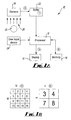
- Fig. 1A illustrates a system 10 for displaying an image captured by a sensor array 14 according to a first embodiment of the present invention.
- the system 10 comprises a plurality of sensors arranged as a sensor array 14, a buffer memory 22, a processor 16, a user input device 24, a display 12 and a memory 18.
- the system 10 may be a component of a digital camera, or an electronic device that displays images captured by a digital camera or has a digital camera integrated into it.
- the system 10 may, for example, be comprised wholly or partly in a portable handheld device, such as a mobile phone or a personal digital assistant (PDA) or may be a personal computer.
- a portable handheld device such as a mobile phone or a personal digital assistant (PDA)
- PDA personal digital assistant
- the sensor array 14 may comprise any suitable light sensors and may, for example comprise charge coupled devices (CCD's) or complementary metal oxide semiconductor (CMOS) sensors.
- CCD's charge coupled devices
- CMOS complementary metal oxide semiconductor
- the sensor array captures an image as image data.
- This data typically comprises a data element (word) for each sensor of the sensor array 14.
- Each data element represents the intensity of the light sensed by the respective sensor.
- the image data is output from the sensor array 14 to the buffer memory 22, which temporarily stores the image data before it is processed by the processor 16. This enables the system 10 to capture data at a rate that is greater than the processing rate of the processor 16 until the buffer memory 22 overflows.
- the processor 16 is connected to the user input device 24 from which it receives command signals.
- the user input device 24 may be any suitable user input device and may, for example be a keypad, a joystick or a touch sensitive screen.
- the user input device 24 is an integral component of the system 10. However, in other implementations it may be separate and remote, and connectable to the processor 16 via a wireless link such as a low power radio frequency link.
- the processor 16 is connected to control the operation of the display 12.
- the display 12 may be any suitable display and may for example be a liquid crystal display (LCD) or a thin film transistor (TFT) display.
- the content of the display 12 is determined by display data provided by the processor 16.
- the display data is a sub-set of the image data.
- the processor 16 is connected to write to and read from the memory 18.
- the processor 16 is operable to store the image data and/or display data in the memory for future use.
- the memory 18 may be any suitable memory and may, for example be built-in permanent memory such as flash memory or it may be a removable memory such as a secure digital (SD) card or a micro-drive.
- SD secure digital
- the system 10 is arranged so that light, incident on the plurality of sensors 14, is converted into image data and then processed by a processor 16 in response to a user input from the user input device 24 to produce display data that determines the image displayed on the display 12.
- Fig. 1A illustrates that the sensor array 14 receives light (represented by arrows 20) from at least one source 21 and produces image data (a).
- the sensor array is an N x M array of sensors and the image data may be represented as a N x M array of data elements as illustrated in Fig 1B, where each data element corresponds to a respective sensor output.
- the sensor array is illustratively a 4x4 array of sensors and the image data (a) is represented as a 4x4 array of data elements which are numbered 1 to 16.
- the image data is stored in the buffer memory 22.
- the processor 16 reads the image data from the buffer 22 and operates on it to produce the display data (b) illustrated in Fig 1B.
- the operation involves selecting a sub-set from the data elements of the image data. This sub-set corresponds to a first area of the sensor array 14.
- the first area is an n x m area of contiguous sensors in the sensor array 14 and the sub-set is the nm data elements corresponding to the output of the sensors within the first area.
- the image data (b) is then sent to the display 12 for display.
- the size of the first area (n x m) corresponds to the size of the display and each data element of the display data is used to control the intensity of a pixel in the display.
- the display is a 2x2 array of pixels, and the first area is a 2x2 array of sensors within the top right corner of the sensor array 14.
- the image data displayed therefore corresponds to the image data elements 3, 4, 7, 8.
- the 2x2 display is merely illustrative, typically displays will be much larger e.g. an array of 1600 x 1200 pixels (1,920,000 pixels in total).
- the user input device 24 allows a user to change display data (b) without changing the image data (a).
- a user may translate the first area within the sensor array 14 to display a different area of the sensor array.
- the user may use the user input device 24 to select, as the display data, a different sub-set from the data elements of the image data.
- This different subset corresponds to a translation of the first area within the sensory array 14. For example, if the user provides a 'left' command, the first area is translated one to the left so that the display data comprises the image data elements 2, 3, 6 and 7. If the user instead provides a 'down' command, the first area is translated one down so that the display data comprises the image data elements 7, 8, 11 and 12. Therefore, a user may selectively choose which 2 x 2 area of the 4 x 4 sensor array 14 provides input to the 2x2 display. This may help to reduce the physical movement of the camera when the user wants to change the final image.
- Fig. 2A illustrates a system 10 for controlling a display 12 according to a second embodiment of the present invention.
- the system 10 is substantially similar to the system 10 illustrated in Fig. 1A and operates in a similar manner. Where the features of Fig. 2A correspond to the features of Fig. 1A, the same reference numerals are used.
- the system 10 illustrated in Fig. 2A differs from that illustrated in Fig. 1A in that it does not comprise a buffer memory for storing image data from all the sensors of the sensor array 14.
- the processor 16 selectively reads image data from the sensor array 14 which is then used as display data.
- the display data may be stored in memory 18 or displayed in the display 12. It is not necessary for the system 10 to comprise a buffer memory 22 because the processor controls the output of the sensor array 14.
- the processor 16 obtains an output from only a sub-set of the sensors within the sensor array.
- the sub-set corresponds to a first area of the sensor array 14.
- the first area is an n x m area of contiguous sensors in the sensor array 14 and the image data (display data) is the nm data elements corresponding to the output of the sensors within the first area.
- the user input device 24 allow a user to change display data by changing the image data.
- a user may translate the first area within the sensor array 14 to obtain different image data from different areas of the sensor array 14. For example, if the display data is originally 3, 4, 7, 8 as illustrated in Fig. 2B, and a user provides a 'left' command, the first area is translated one to the left so that the image data (display data) comprises the data elements 2, 3, 6 and 7. If the user instead provides a 'down' command, the first area is translated one down so that the image data (display data) comprises the data elements 7, 8, 11 and 12. Therefore, a user may selectively choose which 2 x 2 area of the 4 x 4 sensor array 14 provides input to the 2x2 display.
- Fig. 3A illustrates a system 10 for controlling a display 12 according to a third embodiment of the present invention.
- the system 10 is similar to the system 10 illustrated in Fig. 1A. Where the features of Fig. 3A correspond to the features of Fig. 1A, the same reference numerals are used.
- the sensor array 14 captures image data (a) which is read by the processor 16.
- the image data (a) comprises MN data elements and corresponds to the output of the whole of the sensor array 14.
- the image data (a) is then stored in the memory 18 by the processor 16.
- a user may provide a request to the processor 16 stating that they only wish to view n x m pixels of the stored image.
- the processor 16 then processes the image data (a) stored in the memory 18 to create display data (b) which is used to control the content of the display 12.
- the processor 16 reads the image data from the memory 18 and operates on it to produce the display data (b).
- the operation involves selecting a sub-set from the data elements of the image data. This sub-set corresponds to a first area of the sensor array 14.
- the first area is an n x m area of contiguous sensors in the sensor array 14 and the sub-set is the nm data elements corresponding to the output of the sensors within the first area.
- the display data (b) may be stored in the memory 18 as a separate entity from the image data (a).
- the user chooses to view a 2x2 image
- the first area is a 2x2 array of sensors within the top right corner of the sensor array 14.
- the image data displayed therefore corresponds to the image data elements 3, 4, 7, 8.
- the 2x2 display is merely illustrative, typically displays will be much larger e.g. an array of 1600 x 1200 pixels (1,920,000 pixels in total).
- the user input device 24 allows a user to change display data (b) without changing the image data (a).
- the user may use the user input device 24 to select, as the display data, a different sub-set from the data elements of the stored image data.
- This different sub-set corresponds to a translation of the first area within the sensor array 14. For example, if the user provides a 'left' command, the first area is translated one to the left so that the display data comprises the image data elements 2, 3, 6 and 7. If the user instead provides a 'down' command, the first area is translated one down so that the display data comprises the image data elements 7, 8, 11 and 12. Therefore, a user may selectively choose which 2 x 2 area of the 4 x 4 sensor array 14 provides input to the 2x2 display.
- the system 10 illustrated in Fig. 3A allows the user to capture the output from the whole of the sensor array as image data (a) and store it in a memory 18. It then allows a user to request the processor 16 to process the stored image (a) to produce display data (b) which corresponds to a first area of a sensor array.
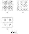
- Fig. 4 illustrates the output from the display 12 when embodiments of the present invention are used in combination with digital zoom.
- Image data (c) comprises thirty six pixels numbered 1 to 36 and corresponds to an entire area of a sensor array.
- display data (d) is produced.
- Display data (d) comprises sixteen data elements from the top right of the image data (c).
- Image (d) corresponds to the first area of the sensor array and may be translated within the sensor array to produce a different image.
- Image (d) may be changed by using digital zoom.
- Digital zoom allows a user to resize the first area of the sensor array to create a resized image.
- the centre of the resized image coincides with the centre of the original image and may be larger or smaller than the original image.
- display data (e) is created which comprises data elements 10, 11, 16 and 17.
- the user may first use digital zoom and then translate the first area within the sensor array to produce a new image. Additionally, it should be appreciated that digital zoom may be used simultaneously with embodiments of the present invention.
- the sensor array should not be limited to the number of sensors defined by the examples above and should be regarded as a plurality of sensors.
- the display should not be limited to the number of pixels described in the examples above and should be regarded as a plurality of pixels.
Landscapes
- Engineering & Computer Science (AREA)
- Multimedia (AREA)
- Signal Processing (AREA)
- Human Computer Interaction (AREA)
- Studio Devices (AREA)
- Controls And Circuits For Display Device (AREA)
- Control Of Indicators Other Than Cathode Ray Tubes (AREA)
- Transforming Light Signals Into Electric Signals (AREA)
- Closed-Circuit Television Systems (AREA)
Applications Claiming Priority (2)
| Application Number | Priority Date | Filing Date | Title |
|---|---|---|---|
| US798815 | 2004-03-10 | ||
| US10/798,815 US7232981B2 (en) | 2004-03-10 | 2004-03-10 | System and a method for displaying an image captured by a sensor array |
Publications (3)
| Publication Number | Publication Date |
|---|---|
| EP1575280A2 true EP1575280A2 (de) | 2005-09-14 |
| EP1575280A3 EP1575280A3 (de) | 2010-09-15 |
| EP1575280B1 EP1575280B1 (de) | 2017-08-16 |
Family
ID=34827669
Family Applications (1)
| Application Number | Title | Priority Date | Filing Date |
|---|---|---|---|
| EP05251468.4A Expired - Lifetime EP1575280B1 (de) | 2004-03-10 | 2005-03-10 | Vorrichtung und Verfahren zur Anzeige von durch ein Sensorfeld aufgenommenes Bild |
Country Status (3)
| Country | Link |
|---|---|
| US (1) | US7232981B2 (de) |
| EP (1) | EP1575280B1 (de) |
| JP (1) | JP4906262B2 (de) |
Families Citing this family (2)
| Publication number | Priority date | Publication date | Assignee | Title |
|---|---|---|---|---|
| US20060005083A1 (en) * | 2004-06-30 | 2006-01-05 | International Business Machines Corporation | Performance count tracing |
| US9219857B2 (en) | 2011-12-21 | 2015-12-22 | Nokia Technologies Oy | Image capture |
Family Cites Families (6)
| Publication number | Priority date | Publication date | Assignee | Title |
|---|---|---|---|---|
| US5428390A (en) * | 1994-01-21 | 1995-06-27 | Texas Instruments Incorporated | Apparatus and method for focal plane zoom and pan |
| US6512858B2 (en) * | 1998-07-21 | 2003-01-28 | Foveon, Inc. | Image scanning circuitry with row and column addressing for use in electronic cameras |
| ES2286875T3 (es) * | 1999-04-22 | 2007-12-01 | Leo Vision | Procedimiento y dispositivo de tratamiento y de restitucion de imagenes, con nuevo muestreo. |
| JP4443735B2 (ja) * | 2000-07-11 | 2010-03-31 | 富士フイルム株式会社 | 撮像装置およびその動作制御方法 |
| US7742073B1 (en) * | 2000-11-01 | 2010-06-22 | Koninklijke Philips Electronics N.V. | Method and apparatus for tracking an object of interest using a camera associated with a hand-held processing device |
| JP3480446B2 (ja) * | 2001-01-11 | 2003-12-22 | ミノルタ株式会社 | デジタルカメラ |
-
2004
- 2004-03-10 US US10/798,815 patent/US7232981B2/en not_active Expired - Lifetime
-
2005
- 2005-03-10 JP JP2005067375A patent/JP4906262B2/ja not_active Expired - Fee Related
- 2005-03-10 EP EP05251468.4A patent/EP1575280B1/de not_active Expired - Lifetime
Also Published As
| Publication number | Publication date |
|---|---|
| EP1575280B1 (de) | 2017-08-16 |
| EP1575280A3 (de) | 2010-09-15 |
| US20050200735A1 (en) | 2005-09-15 |
| US7232981B2 (en) | 2007-06-19 |
| JP2005295531A (ja) | 2005-10-20 |
| JP4906262B2 (ja) | 2012-03-28 |
Similar Documents
| Publication | Publication Date | Title |
|---|---|---|
| JP4395808B2 (ja) | 画面表示部を有する機器の操作装置、デジタルカメラおよびタッチパネル操作方法 | |
| EP2820515B1 (de) | Vorrichtungskamerawinkel | |
| JP4250543B2 (ja) | 撮像装置及び情報処理装置及びそれらの制御方法 | |
| JP5690974B2 (ja) | 撮像装置及び合焦制御方法 | |
| US10484602B2 (en) | Camera arrangements for wide-angle imaging | |
| US8451365B2 (en) | Image control apparatus, image control method, and recording medium | |
| US20110074671A1 (en) | Image display apparatus and control method thereof, and computer program | |
| JP4288134B2 (ja) | 撮像装置 | |
| US20120162459A1 (en) | Image capturing apparatus and image patchwork method thereof | |
| JP2000341644A (ja) | 画像処理装置及び方法並びに記憶媒体 | |
| JP5482327B2 (ja) | 撮像装置、撮像方法および撮像プログラム | |
| CN115428434B (zh) | 摄像装置的处理器、摄像装置、摄像装置的控制方法及存储介质 | |
| KR20050109190A (ko) | 듀얼 카메라를 이용한 와이드 이미지 생성 장치 및 방법 | |
| US7232981B2 (en) | System and a method for displaying an image captured by a sensor array | |
| JP2007052795A (ja) | 画面表示部を有する機器の操作装置およびデジタルカメラ | |
| TWI309800B (en) | Electronic device having a fuction for magnifying/reducing images in-situ adn the method of the same | |
| WO2011141930A1 (en) | Portable electronic device having rotatable | |
| US10863110B2 (en) | Imaging control device, imaging apparatus, imaging control method, and imaging control program | |
| JP2011151515A (ja) | 撮像機能付き電子機器、カメラ機能付き携帯電話機、画像データの表示方法、及び画像データの表示プログラム | |
| JP5324980B2 (ja) | 携帯端末及び画像方向補正方法 | |
| JP2005333340A (ja) | 撮像装置 | |
| JP2006148821A (ja) | ヒストグラム表示装置 | |
| US20050212926A1 (en) | Method and device for processing pixel array data of mobile terminal equipped with digital camera function | |
| US20060203015A1 (en) | Image transformation method and device | |
| WO2025182269A1 (ja) | 撮像装置、制御方法及び制御プログラム |
Legal Events
| Date | Code | Title | Description |
|---|---|---|---|
| PUAI | Public reference made under article 153(3) epc to a published international application that has entered the european phase |
Free format text: ORIGINAL CODE: 0009012 |
|
| AK | Designated contracting states |
Kind code of ref document: A2 Designated state(s): AT BE BG CH CY CZ DE DK EE ES FI FR GB GR HU IE IS IT LI LT LU MC NL PL PT RO SE SI SK TR |
|
| AX | Request for extension of the european patent |
Extension state: AL BA HR LV MK YU |
|
| PUAL | Search report despatched |
Free format text: ORIGINAL CODE: 0009013 |
|
| AK | Designated contracting states |
Kind code of ref document: A3 Designated state(s): AT BE BG CH CY CZ DE DK EE ES FI FR GB GR HU IE IS IT LI LT LU MC NL PL PT RO SE SI SK TR |
|
| AX | Request for extension of the european patent |
Extension state: AL BA HR LV MK YU |
|
| 17P | Request for examination filed |
Effective date: 20110301 |
|
| AKX | Designation fees paid |
Designated state(s): AT BE BG CH CY CZ DE DK EE ES FI FR GB GR HU IE IS IT LI LT LU MC NL PL PT RO SE SI SK TR |
|
| 17Q | First examination report despatched |
Effective date: 20110427 |
|
| RAP1 | Party data changed (applicant data changed or rights of an application transferred) |
Owner name: NOKIA CORPORATION |
|
| RAP1 | Party data changed (applicant data changed or rights of an application transferred) |
Owner name: NOKIA TECHNOLOGIES OY |
|
| GRAP | Despatch of communication of intention to grant a patent |
Free format text: ORIGINAL CODE: EPIDOSNIGR1 |
|
| RIC1 | Information provided on ipc code assigned before grant |
Ipc: H04N 5/225 20060101ALN20170221BHEP Ipc: H04N 5/232 20060101AFI20170221BHEP |
|
| INTG | Intention to grant announced |
Effective date: 20170308 |
|
| RIN1 | Information on inventor provided before grant (corrected) |
Inventor name: YOSHIFUMI, SHIBA |
|
| GRAS | Grant fee paid |
Free format text: ORIGINAL CODE: EPIDOSNIGR3 |
|
| GRAA | (expected) grant |
Free format text: ORIGINAL CODE: 0009210 |
|
| AK | Designated contracting states |
Kind code of ref document: B1 Designated state(s): AT BE BG CH CY CZ DE DK EE ES FI FR GB GR HU IE IS IT LI LT LU MC NL PL PT RO SE SI SK TR |
|
| REG | Reference to a national code |
Ref country code: GB Ref legal event code: FG4D |
|
| REG | Reference to a national code |
Ref country code: CH Ref legal event code: EP |
|
| REG | Reference to a national code |
Ref country code: IE Ref legal event code: FG4D |
|
| REG | Reference to a national code |
Ref country code: AT Ref legal event code: REF Ref document number: 920130 Country of ref document: AT Kind code of ref document: T Effective date: 20170915 |
|
| REG | Reference to a national code |
Ref country code: DE Ref legal event code: R096 Ref document number: 602005052534 Country of ref document: DE |
|
| REG | Reference to a national code |
Ref country code: NL Ref legal event code: MP Effective date: 20170816 |
|
| REG | Reference to a national code |
Ref country code: LT Ref legal event code: MG4D |
|
| REG | Reference to a national code |
Ref country code: AT Ref legal event code: MK05 Ref document number: 920130 Country of ref document: AT Kind code of ref document: T Effective date: 20170816 |
|
| PG25 | Lapsed in a contracting state [announced via postgrant information from national office to epo] |
Ref country code: AT Free format text: LAPSE BECAUSE OF FAILURE TO SUBMIT A TRANSLATION OF THE DESCRIPTION OR TO PAY THE FEE WITHIN THE PRESCRIBED TIME-LIMIT Effective date: 20170816 Ref country code: FI Free format text: LAPSE BECAUSE OF FAILURE TO SUBMIT A TRANSLATION OF THE DESCRIPTION OR TO PAY THE FEE WITHIN THE PRESCRIBED TIME-LIMIT Effective date: 20170816 Ref country code: NL Free format text: LAPSE BECAUSE OF FAILURE TO SUBMIT A TRANSLATION OF THE DESCRIPTION OR TO PAY THE FEE WITHIN THE PRESCRIBED TIME-LIMIT Effective date: 20170816 Ref country code: LT Free format text: LAPSE BECAUSE OF FAILURE TO SUBMIT A TRANSLATION OF THE DESCRIPTION OR TO PAY THE FEE WITHIN THE PRESCRIBED TIME-LIMIT Effective date: 20170816 Ref country code: SE Free format text: LAPSE BECAUSE OF FAILURE TO SUBMIT A TRANSLATION OF THE DESCRIPTION OR TO PAY THE FEE WITHIN THE PRESCRIBED TIME-LIMIT Effective date: 20170816 |
|
| PG25 | Lapsed in a contracting state [announced via postgrant information from national office to epo] |
Ref country code: ES Free format text: LAPSE BECAUSE OF FAILURE TO SUBMIT A TRANSLATION OF THE DESCRIPTION OR TO PAY THE FEE WITHIN THE PRESCRIBED TIME-LIMIT Effective date: 20170816 Ref country code: BG Free format text: LAPSE BECAUSE OF FAILURE TO SUBMIT A TRANSLATION OF THE DESCRIPTION OR TO PAY THE FEE WITHIN THE PRESCRIBED TIME-LIMIT Effective date: 20171116 Ref country code: GR Free format text: LAPSE BECAUSE OF FAILURE TO SUBMIT A TRANSLATION OF THE DESCRIPTION OR TO PAY THE FEE WITHIN THE PRESCRIBED TIME-LIMIT Effective date: 20171117 Ref country code: IS Free format text: LAPSE BECAUSE OF FAILURE TO SUBMIT A TRANSLATION OF THE DESCRIPTION OR TO PAY THE FEE WITHIN THE PRESCRIBED TIME-LIMIT Effective date: 20171216 Ref country code: PL Free format text: LAPSE BECAUSE OF FAILURE TO SUBMIT A TRANSLATION OF THE DESCRIPTION OR TO PAY THE FEE WITHIN THE PRESCRIBED TIME-LIMIT Effective date: 20170816 |
|
| PG25 | Lapsed in a contracting state [announced via postgrant information from national office to epo] |
Ref country code: RO Free format text: LAPSE BECAUSE OF FAILURE TO SUBMIT A TRANSLATION OF THE DESCRIPTION OR TO PAY THE FEE WITHIN THE PRESCRIBED TIME-LIMIT Effective date: 20170816 Ref country code: DK Free format text: LAPSE BECAUSE OF FAILURE TO SUBMIT A TRANSLATION OF THE DESCRIPTION OR TO PAY THE FEE WITHIN THE PRESCRIBED TIME-LIMIT Effective date: 20170816 Ref country code: CZ Free format text: LAPSE BECAUSE OF FAILURE TO SUBMIT A TRANSLATION OF THE DESCRIPTION OR TO PAY THE FEE WITHIN THE PRESCRIBED TIME-LIMIT Effective date: 20170816 |
|
| REG | Reference to a national code |
Ref country code: DE Ref legal event code: R097 Ref document number: 602005052534 Country of ref document: DE |
|
| PG25 | Lapsed in a contracting state [announced via postgrant information from national office to epo] |
Ref country code: IT Free format text: LAPSE BECAUSE OF FAILURE TO SUBMIT A TRANSLATION OF THE DESCRIPTION OR TO PAY THE FEE WITHIN THE PRESCRIBED TIME-LIMIT Effective date: 20170816 Ref country code: SK Free format text: LAPSE BECAUSE OF FAILURE TO SUBMIT A TRANSLATION OF THE DESCRIPTION OR TO PAY THE FEE WITHIN THE PRESCRIBED TIME-LIMIT Effective date: 20170816 Ref country code: EE Free format text: LAPSE BECAUSE OF FAILURE TO SUBMIT A TRANSLATION OF THE DESCRIPTION OR TO PAY THE FEE WITHIN THE PRESCRIBED TIME-LIMIT Effective date: 20170816 |
|
| PLBE | No opposition filed within time limit |
Free format text: ORIGINAL CODE: 0009261 |
|
| STAA | Information on the status of an ep patent application or granted ep patent |
Free format text: STATUS: NO OPPOSITION FILED WITHIN TIME LIMIT |
|
| 26N | No opposition filed |
Effective date: 20180517 |
|
| PG25 | Lapsed in a contracting state [announced via postgrant information from national office to epo] |
Ref country code: SI Free format text: LAPSE BECAUSE OF FAILURE TO SUBMIT A TRANSLATION OF THE DESCRIPTION OR TO PAY THE FEE WITHIN THE PRESCRIBED TIME-LIMIT Effective date: 20170816 |
|
| REG | Reference to a national code |
Ref country code: CH Ref legal event code: PL |
|
| GBPC | Gb: european patent ceased through non-payment of renewal fee |
Effective date: 20180310 |
|
| PG25 | Lapsed in a contracting state [announced via postgrant information from national office to epo] |
Ref country code: MC Free format text: LAPSE BECAUSE OF FAILURE TO SUBMIT A TRANSLATION OF THE DESCRIPTION OR TO PAY THE FEE WITHIN THE PRESCRIBED TIME-LIMIT Effective date: 20170816 |
|
| REG | Reference to a national code |
Ref country code: BE Ref legal event code: MM Effective date: 20180331 |
|
| REG | Reference to a national code |
Ref country code: IE Ref legal event code: MM4A |
|
| PG25 | Lapsed in a contracting state [announced via postgrant information from national office to epo] |
Ref country code: LU Free format text: LAPSE BECAUSE OF NON-PAYMENT OF DUE FEES Effective date: 20180310 |
|
| PG25 | Lapsed in a contracting state [announced via postgrant information from national office to epo] |
Ref country code: IE Free format text: LAPSE BECAUSE OF NON-PAYMENT OF DUE FEES Effective date: 20180310 |
|
| PG25 | Lapsed in a contracting state [announced via postgrant information from national office to epo] |
Ref country code: CH Free format text: LAPSE BECAUSE OF NON-PAYMENT OF DUE FEES Effective date: 20180331 Ref country code: LI Free format text: LAPSE BECAUSE OF NON-PAYMENT OF DUE FEES Effective date: 20180331 Ref country code: BE Free format text: LAPSE BECAUSE OF NON-PAYMENT OF DUE FEES Effective date: 20180331 Ref country code: GB Free format text: LAPSE BECAUSE OF NON-PAYMENT OF DUE FEES Effective date: 20180310 |
|
| PG25 | Lapsed in a contracting state [announced via postgrant information from national office to epo] |
Ref country code: FR Free format text: LAPSE BECAUSE OF NON-PAYMENT OF DUE FEES Effective date: 20180331 |
|
| PG25 | Lapsed in a contracting state [announced via postgrant information from national office to epo] |
Ref country code: TR Free format text: LAPSE BECAUSE OF FAILURE TO SUBMIT A TRANSLATION OF THE DESCRIPTION OR TO PAY THE FEE WITHIN THE PRESCRIBED TIME-LIMIT Effective date: 20170816 |
|
| PG25 | Lapsed in a contracting state [announced via postgrant information from national office to epo] |
Ref country code: HU Free format text: LAPSE BECAUSE OF FAILURE TO SUBMIT A TRANSLATION OF THE DESCRIPTION OR TO PAY THE FEE WITHIN THE PRESCRIBED TIME-LIMIT; INVALID AB INITIO Effective date: 20050310 Ref country code: PT Free format text: LAPSE BECAUSE OF FAILURE TO SUBMIT A TRANSLATION OF THE DESCRIPTION OR TO PAY THE FEE WITHIN THE PRESCRIBED TIME-LIMIT Effective date: 20170816 |
|
| PG25 | Lapsed in a contracting state [announced via postgrant information from national office to epo] |
Ref country code: CY Free format text: LAPSE BECAUSE OF FAILURE TO SUBMIT A TRANSLATION OF THE DESCRIPTION OR TO PAY THE FEE WITHIN THE PRESCRIBED TIME-LIMIT Effective date: 20170816 |
|
| REG | Reference to a national code |
Ref country code: DE Ref legal event code: R079 Ref document number: 602005052534 Country of ref document: DE Free format text: PREVIOUS MAIN CLASS: H04N0005232000 Ipc: H04N0023600000 |
|
| P01 | Opt-out of the competence of the unified patent court (upc) registered |
Effective date: 20230527 |
|
| PGFP | Annual fee paid to national office [announced via postgrant information from national office to epo] |
Ref country code: DE Payment date: 20240130 Year of fee payment: 20 |
|
| REG | Reference to a national code |
Ref country code: DE Ref legal event code: R071 Ref document number: 602005052534 Country of ref document: DE |