EP1575159B1 - Procédé et dispositif pour la génération d'une tension reglée - Google Patents
Procédé et dispositif pour la génération d'une tension reglée Download PDFInfo
- Publication number
- EP1575159B1 EP1575159B1 EP05103944A EP05103944A EP1575159B1 EP 1575159 B1 EP1575159 B1 EP 1575159B1 EP 05103944 A EP05103944 A EP 05103944A EP 05103944 A EP05103944 A EP 05103944A EP 1575159 B1 EP1575159 B1 EP 1575159B1
- Authority
- EP
- European Patent Office
- Prior art keywords
- voltage
- generator
- terminal
- voltage regulator
- field winding
- Prior art date
- Legal status (The legal status is an assumption and is not a legal conclusion. Google has not performed a legal analysis and makes no representation as to the accuracy of the status listed.)
- Expired - Lifetime
Links
Images
Classifications
-
- H—ELECTRICITY
- H02—GENERATION; CONVERSION OR DISTRIBUTION OF ELECTRIC POWER
- H02P—CONTROL OR REGULATION OF ELECTRIC MOTORS, ELECTRIC GENERATORS OR DYNAMO-ELECTRIC CONVERTERS; CONTROLLING TRANSFORMERS, REACTORS OR CHOKE COILS
- H02P9/00—Arrangements for controlling electric generators for the purpose of obtaining a desired output
- H02P9/14—Arrangements for controlling electric generators for the purpose of obtaining a desired output by variation of field
- H02P9/26—Arrangements for controlling electric generators for the purpose of obtaining a desired output by variation of field using discharge tubes or semiconductor devices
- H02P9/30—Arrangements for controlling electric generators for the purpose of obtaining a desired output by variation of field using discharge tubes or semiconductor devices using semiconductor devices
- H02P9/305—Arrangements for controlling electric generators for the purpose of obtaining a desired output by variation of field using discharge tubes or semiconductor devices using semiconductor devices controlling voltage
-
- H—ELECTRICITY
- H02—GENERATION; CONVERSION OR DISTRIBUTION OF ELECTRIC POWER
- H02J—CIRCUIT ARRANGEMENTS OR SYSTEMS FOR SUPPLYING OR DISTRIBUTING ELECTRIC POWER; SYSTEMS FOR STORING ELECTRIC ENERGY
- H02J7/00—Circuit arrangements for charging or depolarising batteries or for supplying loads from batteries
- H02J7/14—Circuit arrangements for charging or depolarising batteries or for supplying loads from batteries for charging batteries from dynamo-electric generators driven at varying speed, e.g. on vehicle
- H02J7/16—Regulation of the charging current or voltage by variation of field
-
- H—ELECTRICITY
- H02—GENERATION; CONVERSION OR DISTRIBUTION OF ELECTRIC POWER
- H02J—CIRCUIT ARRANGEMENTS OR SYSTEMS FOR SUPPLYING OR DISTRIBUTING ELECTRIC POWER; SYSTEMS FOR STORING ELECTRIC ENERGY
- H02J7/00—Circuit arrangements for charging or depolarising batteries or for supplying loads from batteries
- H02J7/14—Circuit arrangements for charging or depolarising batteries or for supplying loads from batteries for charging batteries from dynamo-electric generators driven at varying speed, e.g. on vehicle
- H02J7/1446—Circuit arrangements for charging or depolarising batteries or for supplying loads from batteries for charging batteries from dynamo-electric generators driven at varying speed, e.g. on vehicle in response to parameters of a vehicle
-
- Y—GENERAL TAGGING OF NEW TECHNOLOGICAL DEVELOPMENTS; GENERAL TAGGING OF CROSS-SECTIONAL TECHNOLOGIES SPANNING OVER SEVERAL SECTIONS OF THE IPC; TECHNICAL SUBJECTS COVERED BY FORMER USPC CROSS-REFERENCE ART COLLECTIONS [XRACs] AND DIGESTS
- Y02—TECHNOLOGIES OR APPLICATIONS FOR MITIGATION OR ADAPTATION AGAINST CLIMATE CHANGE
- Y02T—CLIMATE CHANGE MITIGATION TECHNOLOGIES RELATED TO TRANSPORTATION
- Y02T10/00—Road transport of goods or passengers
- Y02T10/80—Technologies aiming to reduce greenhouse gasses emissions common to all road transportation technologies
- Y02T10/92—Energy efficient charging or discharging systems for batteries, ultracapacitors, supercapacitors or double-layer capacitors specially adapted for vehicles
Definitions
- the invention relates to a device and a method for generating a regulated voltage according to the preamble of the main claim.
- a device is used for example in motor vehicles, in which case the generator is driven by the engine or the internal combustion engine of the vehicle.
- a regulated voltage for example, for power supply in a motor vehicle generators are usually used, which are driven by the vehicle engine via a V-belt.
- These generators are usually three-phase generators having a field winding through which the field current flows, a voltage regulator being connected to the generator and regulating the field current so that the output voltage of the generator is substantially constant and slightly higher than the nominal line voltage of the generator charging battery.
- the excitation current is coupled out via the excitation diodes and generated by the generator itself.
- the supply of excitation current via a terminal D +, which is available on both the generator and the voltage regulator.
- the device according to the invention with the features of claim 1 has the advantage that generators including the associated voltage regulator can be used, which are connected to each other only via two terminals and have no D +, L or KL15 connection and that is still ensured in that immediately after starting the generator, ie immediately after the start of the internal combustion engine, a rapid excitation of the generator takes place.
- This advantage is achieved by the voltage regulator information be fed, which indicate that a start is made. It is then immediately established a connection from the positive terminal of the generator via the field winding to ground, over which flows a pre-excitation current, which ensures a rapid start-up of the excitation of the generator.
- the known course of the vehicle electrical system voltage is evaluated during the startup process and from this characteristic curve, a signal is formed, which indicates the start and turns on the exciter current.
- the starter identifier can also be realized using various solutions.
- a starter detection can take place in that the accelerations occurring during the starting process during operation of an internal combustion engine are determined with the aid of an acceleration sensor and serve as start detection signals.
- the amplitude of the phase voltage induced via the residual magnetism of the generator is evaluated for starting detection, and the excitation is started after reaching a limit value.
- the frequency of the phase voltage induced via the residual magnetism is evaluated for the start detection. It can then be started from a predetermined speed, the excitation.
- the transition from the pre-excitation into the normal control mode can take place when at least one predeterminable criterion is reached.
- a criterion may be that the phase voltage is evaluated, wherein from the phase signal, a speed signal can be obtained and this with a Predetermined speed threshold is compared and when reaching this threshold, the transition to normal control operation is done more parameters needed for control such as battery voltage or battery temperature simulated in the controller, even with advanced voltage regulators no additional terminals needed
- a simulation can be done, for example, vehicle type dependent. It is preferably in conjunction with a so-called "tape end programming" and thus does not take place in the regulator production, but only at the end of the overall system production and is then adjusted if necessary for the application.
- a measure of the height of the excitation current can be obtained and thus the generator utilization can be estimated. This information is advantageously available in the controller and does not need to be supplied via additional input terminals.
- the evaluation of the DF signal allows detection of a voltage reserve and additionally offers the possibility of linking the connection of additional consumers to the presence of a voltage reserve.
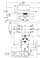
- the most essential components of a power supply system are shown in a motor vehicle.
- the individual components are an alternator 10, which is driven by an internal combustion engine, not shown, and the phase windings U, V, W, which are connected to each other in a common point MP.
- the phase voltage UP arises when the generator is rotating.
- the phase windings are connected to the rectifier bridge 11, which comprises the Zener diodes Z1 to Z6.
- the rectifier bridge 11 is on the one hand to ground and on the other hand leads to the terminal B +, at which the output of the generator, rectified output voltage UG arises.
- the excitation winding E of the generator 10 is connected via the brush holder 12 to the terminals B + and DF of the voltage regulator 13. Between the terminal DF and the terminal D- of the voltage regulator 13, which is guided via the brush holder to ground, is the switching transistor T1, via which the excitation current IE can be controlled by the excitation winding E.
- the basis of Switching transistor T is connected to a circuit block 14, are evaluated in the sensor signals that indicate whether the generator is rotating or whether a start of the internal combustion engine is present.
- the evaluation block in which these signals are evaluated or provided is denoted by 15.
- Another circuit block 16 is used to output the sensor signals, which are designated by US.
- the circuit block 16 is also the phase voltage UP is supplied, which is tapped, for example, at the phase winding V and forwarded via corresponding terminals on the brush holder 12 and voltage regulator 13.
- the circuit block 14 assumes a total of the control of the transistor T.
- the terminal B + of the regulator 13 and the associated terminal of the field winding E are connected together to the generator terminal B +, wherein the connection can be made within the generator 10 via the brush holder 12.
- Between the terminal B + of the voltage regulator and the terminal DF is still a diode D1.
- the circuit blocks 14, 15, 16 may be configured as a microprocessor and be part of the control part of the voltage regulator 13.
- a capacitor C1 is connected between the cathodes of the Zener diodes Z1, Z2, Z3 and ground.
- An additional terminal W may be present, it then communicates with the phase winding W and provides the phase voltage UP.
- the battery 17 is shown, whose positive pole is connected to the generator terminal B + and whose negative terminal is grounded.
- the positive pole of the battery 17 is further connected to terminal KL30, this leads via the ignition switch 18 to the terminal KL15 and thus to Starter 19.
- the consumers are denoted by 20, they can be connected via switching means 21 to the positive pole of the battery 17.
- the lamp / relay controller 23 is also connected to the terminal KL15 and has a control input SE, via the control signals can be fed.
- Parallel to the lamp / relay control 23 is a relay 24th
- the device shown in the figure for generating a regulated output voltage for a vehicle electrical system has between the generator 10 and the electrical system only two connections, namely the terminal B +, at which the regulated and rectified output voltage UG of the generator 10 is tapped to supply the electrical system and the common ground connection D-.
- the existing D + existing in conventional wiring systems deleted.
- the voltage supply for the excitation winding E or the voltage for generating the excitation current IE is tapped generator-internally via terminal B +.
- the connection between the exciter winding and ground is produced with the aid of the transistor T, provided that the base of the transistor T is supplied with a corresponding drive signal. When the generator is stationary, the transistor T blocks and no excitation current flows.
- the accelerations occurring during the starting process can be registered with the aid of an acceleration sensor S for the starting detection.
- This acceleration sensor is mounted at a location of the internal combustion engine in which particularly high acceleration values occur.
- the output signal of the acceleration sensor is supplied to the block 15 of the voltage regulator. It is, for example, a voltage or is conditioned to a voltage, which is referred to as sensor voltage US and is guided to the base of the transistor T of the voltage regulator and this turns on.
- the acceleration sensor can also be integrated in the voltage regulator
- the amplitude of the phase voltage UP induced via the residual magnetism is evaluated. This phase voltage is tapped at the phase V, for example, and fed to the circuit 14. If the amplitude of the phase voltage reaches a limit value, the transistor T of the voltage regulator 13 is activated and the excitation current is switched on. Since the phase voltage or the phase signal already exists in the controller, no additional lines / connections are required.
- the frequency of the phase voltage is dependent on the rotational speed of the generator. By evaluating this frequency, the speed can thus be determined and compared with a predefinable threshold value. If the frequency of the phase voltage exceeds this limit value, a voltage is generated in the circuit 14 which is supplied to the base of the transistor T and puts it in a conductive state.
- the voltage curve at terminal B + is evaluated.
- the course of this voltage during the starting process has some characteristic maxima and minima. If the expected voltage curve is detected, a startup process must have taken place. The recognition of the expected voltage curve is also performed in the circuit 14. If a start is detected, in turn, a control of the transistor T and the excitation current IE is turned on.
- the controller 13 If the speed determined from the phase signal reaches a further threshold value which is higher than the threshold value used for the activation of the excitation current, this is registered by the controller 13 and the controller 13 changes to the normal control state in which the transistor T sets the excitation current IE controls that a constant output voltage UG at the generator terminal B + arises.
- phase voltage UP ⁇ 1V in accordance with a speed against zero or acceleration sensor is evaluated inactive. If the phase voltage UP ⁇ 1V or the acceleration sensor is inactive, motor stall is detected and the excitation current is switched off by switching the transistor T into its blocking state.
- the rotor of the generator can be additionally provided with magnets, as they are already common for example for leakage flux compensation.
- the generator current is switched on erroneously when the motor is stopped as a result of faults or other faults, it is possible, for example, by a timer, e.g. is integrated into the voltage regulator, after a few seconds the excitation current can be switched off again.
- the detection of the stationary motor is possible because the phase signal is missing or no phase voltage is generated.
- the missing phase signal is registered in the circuit arrangement 14. It is then turned on the timer, which switches the transistor T in a blocking state after a certain time. This avoids that the excitation current discharges the battery.
- the generator output voltage UG is regulated as a function of the battery voltage or the battery temperature in an extended controller version, the corresponding information about the battery voltage and / or battery temperature must be present, with conventional voltage regulators this information will be additional Supplied terminals. However, these additional terminals can be dispensed with if the battery voltage and / or battery temperature in the controller is calculated or simulated from already existing data.
- This simulation can be carried out in an evaluation device of the controller 13, which is designed for example as a microprocessor. It can be done taking into account the sensor information which is present anyway in the voltage regulator.
- the simulation may be vehicle-type dependent and, for example, performed as end-of-tape programming.
- the controller is not programmed or calibrated during production, but only after assembly with the generator or after installation in the vehicle.
- connection DF between the voltage regulator 13 and the brush holder 12 does not have to be routed as a separate connection to the outside, since consumers are present in the electrical system, which are to be switched only with power reserve in the electrical system, an evaluation of the supply voltage UG can be performed to detect whether there is still an energy reserve or not. A high supply voltage indicates that this reserve is still present and the consumers can be switched on, a low supply voltage means that there is no reserve and the consumers should be switched off.
- the controller Since the power supply system described requires no control lines, fewer connections are available, which must be provided with a protective circuit. Overall, the controller is insensitive to electromagnetic interference. The EMC is thus improved compared to conventional systems.
- the described device for generating a regulated voltage enables voltage regulation methods, which can be optimally adapted to the requirements in a vehicle electrical system.
Landscapes
- Engineering & Computer Science (AREA)
- Power Engineering (AREA)
- Control Of Eletrric Generators (AREA)
Claims (4)
- Dispositif pour générer une tension régulée comprenant un générateur entraîné par un moteur à combustion interne, et ayant un enroulement d'excitation et un système redresseur et relié à un régulateur de tension (13) par une première borne (B+) fournissant la tension de générateur, régulée, redressée (UG), cette tension de générateur (UG) alimentant le réseau embarqué et la première borne (B+) du générateur (10) est reliée à l'enroulement d'excitation (E) et le passage du courant (IE) est influencé par l'enroulement d'excitation (E) à l'aide d'un moyen de commutation (T),
le moyen de commutation (T) recevant un signal (US) dépendant de la vitesse de rotation du générateur et le signal (US) est généré par un dispositif de commutation (14) faisant partie d'un régulateur de tension (13), en fonction de l'évolution de la tension du réseau embarqué sur la borne (B+),
le démarrage du moteur à combustion interne et ainsi le début de la rotation du générateur (10) étant détectés par l'exploitation du signal (US) et lorsque le démarrage est détecté, l'enroulement d'excitation (E) est relié à la borne (B+) par une commande correspondante du moyen de commutation (T),
le passage du courant à travers l'enroulement d'excitation (E) étant déclenché par le branchement du moyen de commutation (T),
caractérisé en ce que
le générateur (10) est relié par une seconde borne qui est la borne de masse commune (D-), au régulateur de tension (13) et l'opération de démarrage se détecte en comparant la courbe de tension sur la borne (B+) et une courbe de tension prévisible, en détectant les maxima et minima caractéristiques. - Dispositif selon la revendication 1,
caractérisé en ce que
le moyen de commutation (T) est un transistor notamment le transistor de régulation du régulateur de tension (13). - Dispositif selon les revendications précédentes,
caractérisé en ce que
le régulateur de tension comporte des moyens notamment un microprocesseur simulant la grandeur nécessaire à la régulation telle que la tension de batterie ou la température de batterie, la simulation se faisant en fonction des grandeurs mesurées dans le régulateur et/ou en fonction du type de véhicule. - Dispositif selon les revendications précédentes,
caractérisé en ce que
la sollicitation du générateur se détermine par l'exploitation du rapport de travail (marche/arrêt) du régulateur de tension.
Applications Claiming Priority (3)
| Application Number | Priority Date | Filing Date | Title |
|---|---|---|---|
| DE19611908 | 1996-03-26 | ||
| DE19611908A DE19611908A1 (de) | 1996-03-26 | 1996-03-26 | Vorrichtung und Verfahren zur Erzeugung einer geregelten Spannung |
| EP96946191A EP0829124B1 (fr) | 1996-03-26 | 1996-12-12 | Dispositif pour la generation d'une tension regulee |
Related Parent Applications (1)
| Application Number | Title | Priority Date | Filing Date |
|---|---|---|---|
| EP96946191A Division EP0829124B1 (fr) | 1996-03-26 | 1996-12-12 | Dispositif pour la generation d'une tension regulee |
Publications (3)
| Publication Number | Publication Date |
|---|---|
| EP1575159A2 EP1575159A2 (fr) | 2005-09-14 |
| EP1575159A3 EP1575159A3 (fr) | 2007-01-24 |
| EP1575159B1 true EP1575159B1 (fr) | 2008-11-26 |
Family
ID=7789461
Family Applications (2)
| Application Number | Title | Priority Date | Filing Date |
|---|---|---|---|
| EP96946191A Expired - Lifetime EP0829124B1 (fr) | 1996-03-26 | 1996-12-12 | Dispositif pour la generation d'une tension regulee |
| EP05103944A Expired - Lifetime EP1575159B1 (fr) | 1996-03-26 | 1996-12-12 | Procédé et dispositif pour la génération d'une tension reglée |
Family Applications Before (1)
| Application Number | Title | Priority Date | Filing Date |
|---|---|---|---|
| EP96946191A Expired - Lifetime EP0829124B1 (fr) | 1996-03-26 | 1996-12-12 | Dispositif pour la generation d'une tension regulee |
Country Status (6)
| Country | Link |
|---|---|
| EP (2) | EP0829124B1 (fr) |
| JP (1) | JP3863187B2 (fr) |
| KR (1) | KR19990022002A (fr) |
| DE (3) | DE19611908A1 (fr) |
| PL (1) | PL323353A1 (fr) |
| WO (1) | WO1997036360A1 (fr) |
Families Citing this family (7)
| Publication number | Priority date | Publication date | Assignee | Title |
|---|---|---|---|---|
| JP4232071B2 (ja) * | 2000-07-12 | 2009-03-04 | 株式会社デンソー | 車両用交流発電機の制御装置 |
| JP3519048B2 (ja) * | 2000-10-18 | 2004-04-12 | 三菱電機株式会社 | 車両用交流発電機の電圧制御装置 |
| DE10144158B4 (de) * | 2001-09-07 | 2005-02-10 | Webasto Thermosysteme International Gmbh | Kraftfahrzeugzusatzheizgerät |
| DE102004015126A1 (de) | 2004-03-27 | 2005-10-13 | Robert Bosch Gmbh | Verfahren und Vorrichtung zur Übertragung einer Kennung für den Typ eines Generators an ein Steuergerät eines Kraftfahrzeugs |
| DE102004037259A1 (de) * | 2004-07-31 | 2006-02-16 | Robert Bosch Gmbh | Verfahren zur Einstellung vorgebbarer Parameter |
| DE102011007331A1 (de) * | 2011-04-13 | 2012-10-18 | Robert Bosch Gmbh | Verfahren zur Erfassung einer Drehung eines Rotors eines Generators |
| CN109104049A (zh) * | 2018-09-14 | 2018-12-28 | 珠海格力电器股份有限公司 | 电机系统和空调 |
Family Cites Families (6)
| Publication number | Priority date | Publication date | Assignee | Title |
|---|---|---|---|---|
| US4079306A (en) * | 1975-07-22 | 1978-03-14 | Nippondenso Co., Ltd. | Current generating system for motor vehicle |
| DE2806597A1 (de) * | 1978-02-16 | 1979-08-30 | Bosch Gmbh Robert | Schaltungsanordnung zur verbesserung der selbsterregung von generatoren |
| JPS5537881A (en) * | 1978-09-08 | 1980-03-17 | Nippon Denso Co | Automotive generator voltage controller |
| FR2497016B1 (fr) * | 1980-12-24 | 1986-11-14 | Ducellier & Cie | Dispositif de charge de batterie, notamment pour vehicule automobile |
| DE68905509T2 (de) * | 1988-02-23 | 1993-07-01 | Valeo Equip Electr Moteur | Mehrfunktionsregeleinrichtung mit taktsynchronwechselstromerzeuger. |
| FR2649797B1 (fr) * | 1989-07-11 | 1991-10-31 | Valeo Equip Electr Moteur | Circuit de detection du signal phase alternateur polyphase de controle d'un regulateur de charge de batterie de vehicule automobile et son utilisation |
-
1996
- 1996-03-26 DE DE19611908A patent/DE19611908A1/de not_active Ceased
- 1996-12-12 DE DE59611260T patent/DE59611260D1/de not_active Expired - Lifetime
- 1996-12-12 EP EP96946191A patent/EP0829124B1/fr not_active Expired - Lifetime
- 1996-12-12 KR KR1019970708477A patent/KR19990022002A/ko not_active Application Discontinuation
- 1996-12-12 JP JP53391497A patent/JP3863187B2/ja not_active Expired - Lifetime
- 1996-12-12 PL PL96323353A patent/PL323353A1/xx unknown
- 1996-12-12 DE DE59611490T patent/DE59611490D1/de not_active Expired - Lifetime
- 1996-12-12 EP EP05103944A patent/EP1575159B1/fr not_active Expired - Lifetime
- 1996-12-12 WO PCT/DE1996/002401 patent/WO1997036360A1/fr active IP Right Grant
Also Published As
| Publication number | Publication date |
|---|---|
| EP1575159A2 (fr) | 2005-09-14 |
| JPH11506300A (ja) | 1999-06-02 |
| WO1997036360A1 (fr) | 1997-10-02 |
| DE59611490D1 (de) | 2009-01-08 |
| KR19990022002A (ko) | 1999-03-25 |
| JP3863187B2 (ja) | 2006-12-27 |
| EP1575159A3 (fr) | 2007-01-24 |
| EP0829124A1 (fr) | 1998-03-18 |
| DE19611908A1 (de) | 1997-10-02 |
| PL323353A1 (en) | 1998-03-30 |
| EP0829124B1 (fr) | 2005-08-17 |
| DE59611260D1 (de) | 2005-09-22 |
Similar Documents
| Publication | Publication Date | Title |
|---|---|---|
| DE102005056069B4 (de) | System und Verfahren zur Bestimmung eines Bruches in einem Ladedraht | |
| EP0487927B1 (fr) | Procédé et appareil pour régler la tension en fonction de l'état de charge de la batterie | |
| DE10118177B4 (de) | Energieversorgungsvorrichtung für Fahrzeuge | |
| EP0577987B1 (fr) | Dispositif pour le contrÔle de la tension de sortie d'une générateur entraîné par un moteur à combustion interne | |
| DE102007048996B4 (de) | Steuersystem zum Steuern eines Leistungsgenerators mit Bestimmungsvorrichtung zur Erkennung, ob ein empfangener Befehlswert länger als eine zulässige Dauer unverändert geblieben ist | |
| EP1012961B1 (fr) | Dispositif de reglage de la tension de sortie d'un alternateur triphase | |
| DE19639974A1 (de) | Kontroller zum Umsetzen von manuellem auf automatischen Betrieb einer Fahrzeugtür, die zwischen einer geöffneten und geschlossenen Position beweglich ist | |
| EP1152249A1 (fr) | Dispositif et procedé pour detecter une interruption dans la ligne de charge entre un générateur et une batterie d'un véhicule | |
| EP0927449B1 (fr) | Dispositif de regulation de tension | |
| EP1575159B1 (fr) | Procédé et dispositif pour la génération d'une tension reglée | |
| DE102012103271A1 (de) | Fahrzeug-gestützter Generator, der mit einem Überspannungserfassungsschaltkreis vorgesehen ist | |
| DE19939861B4 (de) | Motor-Laststeuersystem | |
| DE3722762C2 (fr) | ||
| EP1301986B1 (fr) | Dispositif de regulation du courant d'excitation pour un generateur triphase | |
| DE102007023946B4 (de) | Drehstromgenerator-Steuervorrichtung für ein Kraftfahrzeug mit einer Umschalteinrichtung für einen Lastreaktionskoeffizienten | |
| EP1469587B1 (fr) | Appareil pour améliorer le fonctionnement d'arrêt et de redémarrage d' un véhicule | |
| DE19608992B4 (de) | Generatoranlage für eine Brennkraftmaschine | |
| DE3308415C2 (fr) | ||
| EP1733472B1 (fr) | Procede et dispositif pour transmettre une identification du type d'un generateur a un appareil de commande d'une automobile | |
| EP1363017B1 (fr) | Circuit pour une machine électrique (démarreur-générateur) avec une pompe de charge passive | |
| DE19634096A1 (de) | Spannungsversorgungssystem mit erhöhter Ausgangsleistung | |
| DE10144158B4 (de) | Kraftfahrzeugzusatzheizgerät | |
| EP1386789A2 (fr) | Dispositif et méthode de régulation d'un réseau de distribution automobile | |
| DE102018215898A1 (de) | Laderegler für eine Drehstromlichtmaschine | |
| DE102008049804A1 (de) | Fahrzeugenergiebordnetz |
Legal Events
| Date | Code | Title | Description |
|---|---|---|---|
| PUAI | Public reference made under article 153(3) epc to a published international application that has entered the european phase |
Free format text: ORIGINAL CODE: 0009012 |
|
| AC | Divisional application: reference to earlier application |
Ref document number: 0829124 Country of ref document: EP Kind code of ref document: P |
|
| AK | Designated contracting states |
Kind code of ref document: A2 Designated state(s): DE FR GB IT |
|
| PUAL | Search report despatched |
Free format text: ORIGINAL CODE: 0009013 |
|
| AK | Designated contracting states |
Kind code of ref document: A3 Designated state(s): DE FR GB IT |
|
| 17P | Request for examination filed |
Effective date: 20070724 |
|
| AKX | Designation fees paid |
Designated state(s): DE FR GB IT |
|
| 17Q | First examination report despatched |
Effective date: 20070926 |
|
| GRAP | Despatch of communication of intention to grant a patent |
Free format text: ORIGINAL CODE: EPIDOSNIGR1 |
|
| GRAS | Grant fee paid |
Free format text: ORIGINAL CODE: EPIDOSNIGR3 |
|
| GRAA | (expected) grant |
Free format text: ORIGINAL CODE: 0009210 |
|
| AC | Divisional application: reference to earlier application |
Ref document number: 0829124 Country of ref document: EP Kind code of ref document: P |
|
| AK | Designated contracting states |
Kind code of ref document: B1 Designated state(s): DE FR GB IT |
|
| REG | Reference to a national code |
Ref country code: GB Ref legal event code: FG4D Free format text: NOT ENGLISH |
|
| REF | Corresponds to: |
Ref document number: 59611490 Country of ref document: DE Date of ref document: 20090108 Kind code of ref document: P |
|
| PLBE | No opposition filed within time limit |
Free format text: ORIGINAL CODE: 0009261 |
|
| STAA | Information on the status of an ep patent application or granted ep patent |
Free format text: STATUS: NO OPPOSITION FILED WITHIN TIME LIMIT |
|
| 26N | No opposition filed |
Effective date: 20090827 |
|
| PGFP | Annual fee paid to national office [announced via postgrant information from national office to epo] |
Ref country code: GB Payment date: 20101221 Year of fee payment: 15 |
|
| PGFP | Annual fee paid to national office [announced via postgrant information from national office to epo] |
Ref country code: IT Payment date: 20101228 Year of fee payment: 15 |
|
| PGFP | Annual fee paid to national office [announced via postgrant information from national office to epo] |
Ref country code: FR Payment date: 20120103 Year of fee payment: 16 |
|
| PGFP | Annual fee paid to national office [announced via postgrant information from national office to epo] |
Ref country code: DE Payment date: 20120221 Year of fee payment: 16 |
|
| GBPC | Gb: european patent ceased through non-payment of renewal fee |
Effective date: 20121212 |
|
| REG | Reference to a national code |
Ref country code: FR Ref legal event code: ST Effective date: 20130830 |
|
| REG | Reference to a national code |
Ref country code: DE Ref legal event code: R119 Ref document number: 59611490 Country of ref document: DE Effective date: 20130702 |
|
| PG25 | Lapsed in a contracting state [announced via postgrant information from national office to epo] |
Ref country code: DE Free format text: LAPSE BECAUSE OF NON-PAYMENT OF DUE FEES Effective date: 20130702 |
|
| PG25 | Lapsed in a contracting state [announced via postgrant information from national office to epo] |
Ref country code: GB Free format text: LAPSE BECAUSE OF NON-PAYMENT OF DUE FEES Effective date: 20121212 Ref country code: FR Free format text: LAPSE BECAUSE OF NON-PAYMENT OF DUE FEES Effective date: 20130102 |
|
| PG25 | Lapsed in a contracting state [announced via postgrant information from national office to epo] |
Ref country code: IT Free format text: LAPSE BECAUSE OF NON-PAYMENT OF DUE FEES Effective date: 20121212 |