EP1575159B1 - Method and device for generating a regulated voltage - Google Patents
Method and device for generating a regulated voltage Download PDFInfo
- Publication number
- EP1575159B1 EP1575159B1 EP05103944A EP05103944A EP1575159B1 EP 1575159 B1 EP1575159 B1 EP 1575159B1 EP 05103944 A EP05103944 A EP 05103944A EP 05103944 A EP05103944 A EP 05103944A EP 1575159 B1 EP1575159 B1 EP 1575159B1
- Authority
- EP
- European Patent Office
- Prior art keywords
- voltage
- generator
- terminal
- voltage regulator
- field winding
- Prior art date
- Legal status (The legal status is an assumption and is not a legal conclusion. Google has not performed a legal analysis and makes no representation as to the accuracy of the status listed.)
- Expired - Lifetime
Links
Images
Classifications
-
- H—ELECTRICITY
- H02—GENERATION; CONVERSION OR DISTRIBUTION OF ELECTRIC POWER
- H02P—CONTROL OR REGULATION OF ELECTRIC MOTORS, ELECTRIC GENERATORS OR DYNAMO-ELECTRIC CONVERTERS; CONTROLLING TRANSFORMERS, REACTORS OR CHOKE COILS
- H02P9/00—Arrangements for controlling electric generators for the purpose of obtaining a desired output
- H02P9/14—Arrangements for controlling electric generators for the purpose of obtaining a desired output by variation of field
- H02P9/26—Arrangements for controlling electric generators for the purpose of obtaining a desired output by variation of field using discharge tubes or semiconductor devices
- H02P9/30—Arrangements for controlling electric generators for the purpose of obtaining a desired output by variation of field using discharge tubes or semiconductor devices using semiconductor devices
- H02P9/305—Arrangements for controlling electric generators for the purpose of obtaining a desired output by variation of field using discharge tubes or semiconductor devices using semiconductor devices controlling voltage
-
- H—ELECTRICITY
- H02—GENERATION; CONVERSION OR DISTRIBUTION OF ELECTRIC POWER
- H02J—CIRCUIT ARRANGEMENTS OR SYSTEMS FOR SUPPLYING OR DISTRIBUTING ELECTRIC POWER; SYSTEMS FOR STORING ELECTRIC ENERGY
- H02J7/00—Circuit arrangements for charging or depolarising batteries or for supplying loads from batteries
- H02J7/14—Circuit arrangements for charging or depolarising batteries or for supplying loads from batteries for charging batteries from dynamo-electric generators driven at varying speed, e.g. on vehicle
- H02J7/16—Regulation of the charging current or voltage by variation of field
-
- H—ELECTRICITY
- H02—GENERATION; CONVERSION OR DISTRIBUTION OF ELECTRIC POWER
- H02J—CIRCUIT ARRANGEMENTS OR SYSTEMS FOR SUPPLYING OR DISTRIBUTING ELECTRIC POWER; SYSTEMS FOR STORING ELECTRIC ENERGY
- H02J7/00—Circuit arrangements for charging or depolarising batteries or for supplying loads from batteries
- H02J7/14—Circuit arrangements for charging or depolarising batteries or for supplying loads from batteries for charging batteries from dynamo-electric generators driven at varying speed, e.g. on vehicle
- H02J7/1446—Circuit arrangements for charging or depolarising batteries or for supplying loads from batteries for charging batteries from dynamo-electric generators driven at varying speed, e.g. on vehicle in response to parameters of a vehicle
-
- Y—GENERAL TAGGING OF NEW TECHNOLOGICAL DEVELOPMENTS; GENERAL TAGGING OF CROSS-SECTIONAL TECHNOLOGIES SPANNING OVER SEVERAL SECTIONS OF THE IPC; TECHNICAL SUBJECTS COVERED BY FORMER USPC CROSS-REFERENCE ART COLLECTIONS [XRACs] AND DIGESTS
- Y02—TECHNOLOGIES OR APPLICATIONS FOR MITIGATION OR ADAPTATION AGAINST CLIMATE CHANGE
- Y02T—CLIMATE CHANGE MITIGATION TECHNOLOGIES RELATED TO TRANSPORTATION
- Y02T10/00—Road transport of goods or passengers
- Y02T10/80—Technologies aiming to reduce greenhouse gasses emissions common to all road transportation technologies
- Y02T10/92—Energy efficient charging or discharging systems for batteries, ultracapacitors, supercapacitors or double-layer capacitors specially adapted for vehicles
Definitions
- the invention relates to a device and a method for generating a regulated voltage according to the preamble of the main claim.
- a device is used for example in motor vehicles, in which case the generator is driven by the engine or the internal combustion engine of the vehicle.
- a regulated voltage for example, for power supply in a motor vehicle generators are usually used, which are driven by the vehicle engine via a V-belt.
- These generators are usually three-phase generators having a field winding through which the field current flows, a voltage regulator being connected to the generator and regulating the field current so that the output voltage of the generator is substantially constant and slightly higher than the nominal line voltage of the generator charging battery.
- the excitation current is coupled out via the excitation diodes and generated by the generator itself.
- the supply of excitation current via a terminal D +, which is available on both the generator and the voltage regulator.
- the device according to the invention with the features of claim 1 has the advantage that generators including the associated voltage regulator can be used, which are connected to each other only via two terminals and have no D +, L or KL15 connection and that is still ensured in that immediately after starting the generator, ie immediately after the start of the internal combustion engine, a rapid excitation of the generator takes place.
- This advantage is achieved by the voltage regulator information be fed, which indicate that a start is made. It is then immediately established a connection from the positive terminal of the generator via the field winding to ground, over which flows a pre-excitation current, which ensures a rapid start-up of the excitation of the generator.
- the known course of the vehicle electrical system voltage is evaluated during the startup process and from this characteristic curve, a signal is formed, which indicates the start and turns on the exciter current.
- the starter identifier can also be realized using various solutions.
- a starter detection can take place in that the accelerations occurring during the starting process during operation of an internal combustion engine are determined with the aid of an acceleration sensor and serve as start detection signals.
- the amplitude of the phase voltage induced via the residual magnetism of the generator is evaluated for starting detection, and the excitation is started after reaching a limit value.
- the frequency of the phase voltage induced via the residual magnetism is evaluated for the start detection. It can then be started from a predetermined speed, the excitation.
- the transition from the pre-excitation into the normal control mode can take place when at least one predeterminable criterion is reached.
- a criterion may be that the phase voltage is evaluated, wherein from the phase signal, a speed signal can be obtained and this with a Predetermined speed threshold is compared and when reaching this threshold, the transition to normal control operation is done more parameters needed for control such as battery voltage or battery temperature simulated in the controller, even with advanced voltage regulators no additional terminals needed
- a simulation can be done, for example, vehicle type dependent. It is preferably in conjunction with a so-called "tape end programming" and thus does not take place in the regulator production, but only at the end of the overall system production and is then adjusted if necessary for the application.
- a measure of the height of the excitation current can be obtained and thus the generator utilization can be estimated. This information is advantageously available in the controller and does not need to be supplied via additional input terminals.
- the evaluation of the DF signal allows detection of a voltage reserve and additionally offers the possibility of linking the connection of additional consumers to the presence of a voltage reserve.
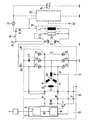
- the most essential components of a power supply system are shown in a motor vehicle.
- the individual components are an alternator 10, which is driven by an internal combustion engine, not shown, and the phase windings U, V, W, which are connected to each other in a common point MP.
- the phase voltage UP arises when the generator is rotating.
- the phase windings are connected to the rectifier bridge 11, which comprises the Zener diodes Z1 to Z6.
- the rectifier bridge 11 is on the one hand to ground and on the other hand leads to the terminal B +, at which the output of the generator, rectified output voltage UG arises.
- the excitation winding E of the generator 10 is connected via the brush holder 12 to the terminals B + and DF of the voltage regulator 13. Between the terminal DF and the terminal D- of the voltage regulator 13, which is guided via the brush holder to ground, is the switching transistor T1, via which the excitation current IE can be controlled by the excitation winding E.
- the basis of Switching transistor T is connected to a circuit block 14, are evaluated in the sensor signals that indicate whether the generator is rotating or whether a start of the internal combustion engine is present.
- the evaluation block in which these signals are evaluated or provided is denoted by 15.
- Another circuit block 16 is used to output the sensor signals, which are designated by US.
- the circuit block 16 is also the phase voltage UP is supplied, which is tapped, for example, at the phase winding V and forwarded via corresponding terminals on the brush holder 12 and voltage regulator 13.
- the circuit block 14 assumes a total of the control of the transistor T.
- the terminal B + of the regulator 13 and the associated terminal of the field winding E are connected together to the generator terminal B +, wherein the connection can be made within the generator 10 via the brush holder 12.
- Between the terminal B + of the voltage regulator and the terminal DF is still a diode D1.
- the circuit blocks 14, 15, 16 may be configured as a microprocessor and be part of the control part of the voltage regulator 13.
- a capacitor C1 is connected between the cathodes of the Zener diodes Z1, Z2, Z3 and ground.
- An additional terminal W may be present, it then communicates with the phase winding W and provides the phase voltage UP.
- the battery 17 is shown, whose positive pole is connected to the generator terminal B + and whose negative terminal is grounded.
- the positive pole of the battery 17 is further connected to terminal KL30, this leads via the ignition switch 18 to the terminal KL15 and thus to Starter 19.
- the consumers are denoted by 20, they can be connected via switching means 21 to the positive pole of the battery 17.
- the lamp / relay controller 23 is also connected to the terminal KL15 and has a control input SE, via the control signals can be fed.
- Parallel to the lamp / relay control 23 is a relay 24th
- the device shown in the figure for generating a regulated output voltage for a vehicle electrical system has between the generator 10 and the electrical system only two connections, namely the terminal B +, at which the regulated and rectified output voltage UG of the generator 10 is tapped to supply the electrical system and the common ground connection D-.
- the existing D + existing in conventional wiring systems deleted.
- the voltage supply for the excitation winding E or the voltage for generating the excitation current IE is tapped generator-internally via terminal B +.
- the connection between the exciter winding and ground is produced with the aid of the transistor T, provided that the base of the transistor T is supplied with a corresponding drive signal. When the generator is stationary, the transistor T blocks and no excitation current flows.
- the accelerations occurring during the starting process can be registered with the aid of an acceleration sensor S for the starting detection.
- This acceleration sensor is mounted at a location of the internal combustion engine in which particularly high acceleration values occur.
- the output signal of the acceleration sensor is supplied to the block 15 of the voltage regulator. It is, for example, a voltage or is conditioned to a voltage, which is referred to as sensor voltage US and is guided to the base of the transistor T of the voltage regulator and this turns on.
- the acceleration sensor can also be integrated in the voltage regulator
- the amplitude of the phase voltage UP induced via the residual magnetism is evaluated. This phase voltage is tapped at the phase V, for example, and fed to the circuit 14. If the amplitude of the phase voltage reaches a limit value, the transistor T of the voltage regulator 13 is activated and the excitation current is switched on. Since the phase voltage or the phase signal already exists in the controller, no additional lines / connections are required.
- the frequency of the phase voltage is dependent on the rotational speed of the generator. By evaluating this frequency, the speed can thus be determined and compared with a predefinable threshold value. If the frequency of the phase voltage exceeds this limit value, a voltage is generated in the circuit 14 which is supplied to the base of the transistor T and puts it in a conductive state.
- the voltage curve at terminal B + is evaluated.
- the course of this voltage during the starting process has some characteristic maxima and minima. If the expected voltage curve is detected, a startup process must have taken place. The recognition of the expected voltage curve is also performed in the circuit 14. If a start is detected, in turn, a control of the transistor T and the excitation current IE is turned on.
- the controller 13 If the speed determined from the phase signal reaches a further threshold value which is higher than the threshold value used for the activation of the excitation current, this is registered by the controller 13 and the controller 13 changes to the normal control state in which the transistor T sets the excitation current IE controls that a constant output voltage UG at the generator terminal B + arises.
- phase voltage UP ⁇ 1V in accordance with a speed against zero or acceleration sensor is evaluated inactive. If the phase voltage UP ⁇ 1V or the acceleration sensor is inactive, motor stall is detected and the excitation current is switched off by switching the transistor T into its blocking state.
- the rotor of the generator can be additionally provided with magnets, as they are already common for example for leakage flux compensation.
- the generator current is switched on erroneously when the motor is stopped as a result of faults or other faults, it is possible, for example, by a timer, e.g. is integrated into the voltage regulator, after a few seconds the excitation current can be switched off again.
- the detection of the stationary motor is possible because the phase signal is missing or no phase voltage is generated.
- the missing phase signal is registered in the circuit arrangement 14. It is then turned on the timer, which switches the transistor T in a blocking state after a certain time. This avoids that the excitation current discharges the battery.
- the generator output voltage UG is regulated as a function of the battery voltage or the battery temperature in an extended controller version, the corresponding information about the battery voltage and / or battery temperature must be present, with conventional voltage regulators this information will be additional Supplied terminals. However, these additional terminals can be dispensed with if the battery voltage and / or battery temperature in the controller is calculated or simulated from already existing data.
- This simulation can be carried out in an evaluation device of the controller 13, which is designed for example as a microprocessor. It can be done taking into account the sensor information which is present anyway in the voltage regulator.
- the simulation may be vehicle-type dependent and, for example, performed as end-of-tape programming.
- the controller is not programmed or calibrated during production, but only after assembly with the generator or after installation in the vehicle.
- connection DF between the voltage regulator 13 and the brush holder 12 does not have to be routed as a separate connection to the outside, since consumers are present in the electrical system, which are to be switched only with power reserve in the electrical system, an evaluation of the supply voltage UG can be performed to detect whether there is still an energy reserve or not. A high supply voltage indicates that this reserve is still present and the consumers can be switched on, a low supply voltage means that there is no reserve and the consumers should be switched off.
- the controller Since the power supply system described requires no control lines, fewer connections are available, which must be provided with a protective circuit. Overall, the controller is insensitive to electromagnetic interference. The EMC is thus improved compared to conventional systems.
- the described device for generating a regulated voltage enables voltage regulation methods, which can be optimally adapted to the requirements in a vehicle electrical system.
Description
Die Erfindung betrifft eine Vorrichtung und ein Verfahren zur Erzeugung einer geregelten Spannung nach der Gattung des Hauptanspruchs. Eine solche Vorrichtung wird beispielsweise in Kraftfahrzeugen eingesetzt, wobei dann der Generator vom Motor beziehungsweise der Brennkraftmaschine des Fahrzeuges angetrieben wird.The invention relates to a device and a method for generating a regulated voltage according to the preamble of the main claim. Such a device is used for example in motor vehicles, in which case the generator is driven by the engine or the internal combustion engine of the vehicle.
Zur Erzeugung einer geregelten Spannung, beispielsweise zur Energieversorgung in einem Kraftfahrzeug werden üblicherweise Generatoren eingesetzt, die vom Fahrzeugmotor über einen Keilriemen angetrieben werden. Diese Generatoren sind üblicherweise Drehstromgeneratoren mit einer Erregerwicklung, die vom Erregerstrom durchflossen wird, wobei ein Spannungsregler mit dem Generator in Verbindung steht und den Erregerstrom so regelt, daß die Ausgangsspannung des Generators im wesentlichen konstant ist und etwas höher ist als die Nennspannung einer vom Generator zu ladenden Batterie. Bei herkömmlichen Generatoren wird der Erregerstrom über die Erregerdioden ausgekoppelt und vom Generator selbst erzeugt. Die Zuführung des Erregerstroms erfolgt über eine Klemme D+, die sowohl am Generator als auch am Spannungsregler vorhanden ist.To generate a regulated voltage, for example, for power supply in a motor vehicle generators are usually used, which are driven by the vehicle engine via a V-belt. These generators are usually three-phase generators having a field winding through which the field current flows, a voltage regulator being connected to the generator and regulating the field current so that the output voltage of the generator is substantially constant and slightly higher than the nominal line voltage of the generator charging battery. In conventional generators, the excitation current is coupled out via the excitation diodes and generated by the generator itself. The supply of excitation current via a terminal D +, which is available on both the generator and the voltage regulator.
Es sind jedoch auch Generator-Spannungsregler-Systeme bekannt, bei denen keine Erregerdioden benötigt werden, da die Erregerwicklung direkt an die Batterie angeschlossen wird. Ein solcher Generator ohne D+- Anschluss ist beispielsweise aus der
Aus der
Die erfindungsgemäße Vorrichtung mit den Merkmalen des Anspruchs 1 hat demgegenüber den Vorteil, dass Generatoren einschließlich der zugehörigen Spannungsregler, eingesetzt werden können, die lediglich über zwei Anschlüsse miteinander verbunden sind und keinen D+-, L- oder KL15-Anschluß aufweisen und dass dennoch sichergestellt wird, dass unmittelbar nach der Inbetriebnahme des Generators, also unmittelbar nach dem Start der Brennkraftmaschine, eine schnelle Erregung des Generators erfolgt. Erzielt wird dieser Vorteil, indem dem Spannungsregler Informationen zugeführt werden, die erkennen lassen, dass ein Start erfolgt. Es wird dann sofort eine Verbindung vom Plus-Anschluss des Generators über die Erregerwicklung nach Masse hergestellt, über die ein Vorerregungsstrom fließt, der ein schnelles Anlaufen der Erregung des Generators sicherstellt.The device according to the invention with the features of
In vorteilhaften Weise wird der an sich bekannte Verlauf der Bordnetzspannung während des Startvorgangs ausgewertet und aus diesem charakteristischen Verlauf ein Signal gebildet, das den Start anzeigt und den Erregerstrom einschaltet.Advantageously, the known course of the vehicle electrical system voltage is evaluated during the startup process and from this characteristic curve, a signal is formed, which indicates the start and turns on the exciter current.
Die Starterkennung kann auch anhand verschiedener Lösungen realisierbar sein. So kann beispielsweise eine Starterkennung erfolgen, indem die während des Startvorgangs beim Betrieb eines Verbrennungsmotors auftretenden Beschleunigungen mit Hilfe eines Beschleunigungssensors ermittelt werden und als Starterkennungssignale dienen. Bei einer anderen vorteilhaften Lösung wird die Amplitude der über den Restmagnetismus des Generators induzierten Phasenspannung zur Starterkennung ausgewertet und die Erregung nach Erreichen eines Grenzwertes gestartet. Bei einer weiteren vorteilhaften Lösung wird die Frequenz der über den Restmagnetismus induzierten Phasenspannung zur Starterkennung ausgewertet. Es kann dann ab einer vorgegebenen Drehzahl die Erregung gestartet werden.The starter identifier can also be realized using various solutions. Thus, for example, a starter detection can take place in that the accelerations occurring during the starting process during operation of an internal combustion engine are determined with the aid of an acceleration sensor and serve as start detection signals. In another advantageous solution, the amplitude of the phase voltage induced via the residual magnetism of the generator is evaluated for starting detection, and the excitation is started after reaching a limit value. In a further advantageous solution, the frequency of the phase voltage induced via the residual magnetism is evaluated for the start detection. It can then be started from a predetermined speed, the excitation.
Bei allen Beispielen der Starterkennung kann der Übergang von der Vorerregung in den normalen Regelbetrieb bei Erreichen wenigstens eines vorgebbaren Kriteriums erfolgen. Ein solches Kriterium kann darin bestehen, dass die Phasenspannung ausgewertet wird, wobei aus dem Phasensignal ein Drehzahlsignal gewonnen werden kann und dieses mit einem vorgebbaren Drehzahl-Schwellwert verglichen wird und bei Erreichen dieses Schwellwertes der Übergang in den normalen Regelbetrieb erfolgt Werden weitere zur Regelung benötigte Größen wie Batteriespannung oder Batterietemperatur im Regler simuliert, werden auch bei erweiterte Spannungsreglern keine zusätzlichen Klemmen benötigt Eine solche Simulation kann beispielsweise fahrzeugtypabhängig erfolgen. Sie eignet sich vorzugsweise in Verbindung mit einer sogenannten "Bandende-Programmierung" und erfolgt also nicht bei der Reglerherstellung, sondern erst am Ende der Gesamtsystemfertigung und wird dann gegebenenfalls für den Anwendungszweck abgeglichen.In all examples of the starter identifier, the transition from the pre-excitation into the normal control mode can take place when at least one predeterminable criterion is reached. Such a criterion may be that the phase voltage is evaluated, wherein from the phase signal, a speed signal can be obtained and this with a Predetermined speed threshold is compared and when reaching this threshold, the transition to normal control operation is done more parameters needed for control such as battery voltage or battery temperature simulated in the controller, even with advanced voltage regulators no additional terminals needed Such a simulation can be done, for example, vehicle type dependent. It is preferably in conjunction with a so-called "tape end programming" and thus does not take place in the regulator production, but only at the end of the overall system production and is then adjusted if necessary for the application.
Durch Auswertung des im Regler vorhanden DF-Signales, das das Tastverhältnis EIN/AUS des Spannungsreglers anzeigt, kann ein Maß für die Höhe des Erregerstromes gewonnen werden und damit die Generatorauslastung abgeschätzt werden. Diese Information steht in vorteilhafter Weise im Regler bereit und muss nicht über zusätzliche Eingangsklemmen zugeführt werden. Die Auswertung des DF-Signales erlaubt eine Erkennung einer Spannungsreserve und bietet zusätzlich die Möglichkeit, die Zuschaltung von weiteren Verbrauchern an das Vorhandensein einer Spannungsreserve zu knüpfen.By evaluating the DF signal present in the controller, which indicates the duty cycle ON / OFF of the voltage regulator, a measure of the height of the excitation current can be obtained and thus the generator utilization can be estimated. This information is advantageously available in the controller and does not need to be supplied via additional input terminals. The evaluation of the DF signal allows detection of a voltage reserve and additionally offers the possibility of linking the connection of additional consumers to the presence of a voltage reserve.
Falls durch Störungseinfluss eine irrtümliche Erregerstromeinschaltung bei stehendem Motor ausgelöst wird, kann dies durch Auswertung des Phasensignales erkannt werden und es kann in vorteilhafter Weise ein Zeitglied nach einer gewissen Zeitspanne von einigen Sekunden aktiviert werden, das seinerseits den Erregerstrom abschaltet. Damit kann eine ungewollte Batterieentladung vermieden werden.If an erroneous exciter current activation is triggered by the influence of interference when the engine is stopped, this can be detected by evaluating the phase signal and it can be activated in a beneficial manner, a timer after a certain period of a few seconds, which in turn shuts off the excitation current. Thus, an unwanted battery discharge can be avoided.
Da gegenüber herkömmlichen Generatoren weniger Anschlüsse und damit auch weniger Verbindungsleitungen erforderlich sind und überhaupt keine Steuerleitungen vorhanden sind, ist eine Erhöhung der Störsicherheit gewährleistet und das System wird gegenüber elektromagnetischen Störungen unempfindlicher.Since compared to conventional generators fewer connections and thus fewer interconnections are required and no control lines are present, an increase in noise immunity is guaranteed and the system is less susceptible to electromagnetic interference.
Ein Ausführungsbeispiel der Erfindung ist in der Zeichnung dargestellt und wird in der nachfolgenden Beschreibung näher erläutert.An embodiment of the invention is illustrated in the drawing and will be explained in more detail in the following description.
In der Figur sind die wesentlichsten Bestandteile eines Spannungsversorgungssystems in einem Kraftfahrzeug dargestellt. Die einzelnen Bestandteile sind ein Drehstromgenerator 10, der von einer nicht dargestellten Brennkraftmaschine angetrieben wird und die Phasenwicklungen U, V, W umfaßt, die in einem gemeinsamen Punkt MP miteinander verbunden sind. Am Ausgang der Phasenwicklungen entsteht bei sich drehendem Generator die Phasenspannung UP. Die Phasenwicklungen sind mit der Gleichrichterbrücke 11 verbunden, die die Zenerdioden Z1 bis Z6 umfaßt. Die Gleichrichterbrücke 11 liegt einerseits auf Masse und führt andererseits zum Anschluß B+, an der die vom Generator abgegebene, gleichgerichtete Ausgangsspannung UG entsteht.In the figure, the most essential components of a power supply system are shown in a motor vehicle. The individual components are an
Die Erregerwicklung E des Generators 10 ist über den Bürstenhalter 12 mit den Anschlüssen B+ und DF des Spannungsreglers 13 verbunden. Zwischen dem Anschluß DF und dem Anschluß D- des Spannungsreglers 13, der über den Bürstenhalter auf Masse geführt ist, liegt der Schalttransistor T1, über den der Erregerstrom IE durch die Erregerwicklung E geregelt werden kann. Die Basis des Schalttransistors T ist mit einem Schaltungsblock 14 verbunden, in dem Sensorsignale ausgewertet werden, die erkennen lassen, ob sich der Generator dreht beziehungsweise ob ein Start der Brennkraftmaschine vorliegt. Der Auswerteblock, in dem diese Signale ausgewertet beziehungsweise bereitgestellt werden, ist mit 15 bezeichnet. Ein weiterer Schaltungsblock 16 dient zur Ausgabe der Sensorsignale, die mit US bezeichnet sind. Dem Schaltungsblock 16 wird auch noch die Phasenspannung UP zugeführt, die beispielsweise an der Phasenwicklung V abgegriffen wird und über entsprechende Anschlüsse am Bürstenhalter 12 beziehungsweise Spannungsregler 13 weitergeleitet werden. Der Schaltungsblock 14 übernimmt insgesamt die Ansteuerung des Transistors T. Der Anschluß B+ des Reglers 13 beziehungsweise der zugehörige Anschluß der Erregerwicklung E sind gemeinsam an die Generatorklemme B+ angeschlossen, wobei der Anschluß innerhalb des Generators 10 über den Bürstenhalter 12 erfolgen kann. Zwischen dem Anschluß B+ des Spannungsreglers und dem Anschluß DF liegt noch eine Diode D1. Die Schaltungsblöcke 14, 15, 16 können als Mikroprozessor ausgestaltet sein und Bestandteil des Steuerteils des Spannungsreglers 13 sein.The excitation winding E of the
Als weiterer Bestandteil des Drehstromgenerators 10 liegt ein Kondensator C1 zwischen den Kathoden der Zenerdioden Z1, Z2, Z3 und Masse. Ein zusätzlicher Anschluß W kann vorhanden sein, er steht dann mit der Phasenwicklung W in Verbindung und liefert die Phasenspannung UP.As a further component of the three-
Vom Fahrzeugbordnetz ist die Batterie 17 dargestellt, deren Pluspol mit der Generatorklemme B+ in Verbindung steht und deren Minuspol auf Masse liegt. Der Pluspol der Batterie 17 ist weiterhin mit Klemme KL30 verbunden, diese führt über den Zündschalter 18 zur Klemme KL15 und damit zum Starter 19. Die Verbraucher sind mit 20 bezeichnet, sie können über Schaltmittel 21 mit dem Pluspol der Batterie 17 verbunden werden.From the vehicle electrical system, the
Als Ergänzung zum Bordnetz kann von Klemme KL15 eine Verbindung zur Ladekontrollampe 22 geführt sein, die über eine Lampen-/Relais-Steuerung 23 auf Masse geführt wird. Die Lampen-/Relais-Steuerung 23 steht ferner mit der Klemme KL15 in Verbindung und weist einen Steuereingang SE auf, über den Steuersignale zuführbar sind. Parallel zur Lampen-/Relais-Steuerung 23 liegt ein Relais 24.As a supplement to the vehicle electrical system can be guided by terminal KL15 a connection to the
Die in der Figur dargestellte Vorrichtung zur Erzeugung einer geregelten Ausgangsspannung für ein Fahrzeugbordnetz hat zwischen dem Generator 10 und dem Bordnetz nur zwei Verbindungen, nämlich den Anschluß B+, an dem die geregelte und gleichgerichtete Ausgangsspannung UG des Generators 10 zur Versorgung des Bordnetzes abgegriffen wird sowie der gemeinsame Masseanschluß D-. Der bei herkömmlichen Bordnetzen vorhandene Anschluß D+ entfällt. Die Spannungsversorgung für die Erregerwicklung E beziehungsweise die Spannung zur Erzeugung des Erregerstromes IE wird generatorintern über Klemme B+ abgegriffen. Die Verbindung zwischen der Erregerwicklung und Masse wird mit Hilfe des Transistors T hergestellt, sofern der Basis des Transistors T ein entsprechendes Ansteuersignal zugeführt wird. Bei stehendem Generator sperrt der Transistor T und es fließt kein Erregerstrom. Erfolgt ein Start der Brennkraftmaschine, beginnt der Generator sich zu drehen und es wird ein Erregerstrom benötigt. Dieser Strom für die Vorerregung wird direkt vom Anschluß B+ geliefert, sobald der Spannungsregler den Start der Brennkraftmaschine erkennt. Für die Starterkennung sind verschiedene Varianten möglich, die im folgenden beschrieben werden:The device shown in the figure for generating a regulated output voltage for a vehicle electrical system has between the
Für die Starterkennung kann beispielsweise die während des Startvorganges auftretenden Beschleunigungen mit Hilfe eines Beschleunigungssensors S registriert. Dieser Beschleunigungssensor wird an einer Stelle der Brennkraftmaschine angebracht, bei der besonders hohe Beschleunigungswerte auftreten. Das Ausgangssignal des Beschleunigungssensors wird dem Block 15 des Spannungsreglers zugeführt. Es ist beispielsweise eine Spannung oder wird zu einer Spannung aufbereitet, die als Sensorspannung US bezeichnet ist und auf die Basis des Transistors T des Spannungsreglers geführt wird und diesen einschaltet. Der Beschleunigungssensor kann auch im Spannungsregler integriert seinFor example, the accelerations occurring during the starting process can be registered with the aid of an acceleration sensor S for the starting detection. This acceleration sensor is mounted at a location of the internal combustion engine in which particularly high acceleration values occur. The output signal of the acceleration sensor is supplied to the
in einem weiteren Beispiel wird die Amplitude der über den Restmagnetismus induzierten Phasenspannung UP ausgewertet Diese Phasenspannung wird beispielsweise an der Phase V abgegriffen und der Schaltung 14 zugeführt. Erreicht die Amplitude der Phasenspannung einen Grenzwert, wird der Transistor T des Spannungsreglers 13 angesteuert und der Erregerstrom eingeschaltet. Da die Phasenspannung bzw. das Phasensignal im Regler bereits vorhanden ist, werden keine zusätzlichen Leitungen/Anschlüsse benötigt.In a further example, the amplitude of the phase voltage UP induced via the residual magnetism is evaluated. This phase voltage is tapped at the phase V, for example, and fed to the circuit 14. If the amplitude of the phase voltage reaches a limit value, the transistor T of the
Es ist auch möglich, die Frequenz der Phasenspannung auszuwerten. Die Frequenz der über den Restmagnetismus induzierten Phasenspannung ist von der Drehzahl des Generators abhängig. Durch Auswertung dieser Frequenz kann somit die Drehzahl ermittelt werden und mit einem vorgebbaren Schwellwert verglichen werden. Überschreitet die Frequenz der Phasenspannung diesen Grenzwert, wird in der Schaltung 14 eine Spannung erzeugt, die Basis des Transistors T zugeführt wird und diesen in leitenden Zustand versetzt.It is also possible to evaluate the frequency of the phase voltage. The frequency of the phase voltage induced via the residual magnetism is dependent on the rotational speed of the generator. By evaluating this frequency, the speed can thus be determined and compared with a predefinable threshold value. If the frequency of the phase voltage exceeds this limit value, a voltage is generated in the circuit 14 which is supplied to the base of the transistor T and puts it in a conductive state.
Erfindungsgemäß wird der Spannungsverlauf an der Klemme B+ ausgewertet. Der Verlauf dieser Spannung während des Startvorgangs weist einige charakteristische Maxima und Minima auf. Wird der erwartete Spannungsverlauf erkannt, muß ein Startvorgang erfolgt sein. Die Erkennung des zu erwartenden Spannungsverlaufs wird ebenfalls in der Schaltungsanordnung 14 durchgeführt. Ist ein Start erkannt, erfolgt wiederum eine Ansteuerung des Transistors T und der Erregerstrom IE wird eingeschaltet.According to the voltage curve at terminal B + is evaluated. The course of this voltage during the starting process has some characteristic maxima and minima. If the expected voltage curve is detected, a startup process must have taken place. The recognition of the expected voltage curve is also performed in the circuit 14. If a start is detected, in turn, a control of the transistor T and the excitation current IE is turned on.
Die bisher beschriebenen verschiedenen Beispiele zur Starterkennung dienen alle dazu, daß unmittelbar nach dem Start der Brennkraftmaschine ein ausreichender Erregerstrom IE durch den Erreger E fließt Nachdem der Generator 10 den vollen Erregungszustand erreicht hat, muß eine Begrenzung des Erregerstromes erfolgen, damit die Ausgangsspannung UG des Generators den gewünschten Wert nicht überschreitet Der Spannungsregler geht dann vom Vorerregungs-Bitriebszustand in den normalen Regelbetrieb über. Die Umschaltung von der Vorerregung auf den normalen Regelbetrieb erfolgt beispielsweise über die Auswertung des Phasensignales. Wie bereits in der Beschreibung des Beispiels 2 oder 3 ausgeführt wird, ist sowohl die Amplitude der Phasenspannung als auch die Frequenz der Phasenspannung von der Drehzahl des Generators abhängig. Die Auswertung des Phasensignals ermöglicht daher eine Drehzahlbestimmung. Erreicht die aus dem Phasensignal ermittelte Drehzahl einen weiteren Schwellwert, der höher liegt als der für die Einschaltung des Erregerstromes verwendete Schwellwert, wird dies vom Regler 13 registriert und der Regler 13 geht in den normalen Regelzustand über, bei dem der Transistor T den Erregerstrom IE so regelt, daß eine konstante Ausgangsspannung UG an der Generatorklemme B+ entsteht.The various examples of starter detection described so far all serve to ensure that a sufficient excitation current IE flows through the exciter E immediately after the start of the internal combustion engine. After the
Beim Abschalten der Brennkraftmaschine wird der Antrieb des Generators beendet und die Generatordrehzahl fällt ab. Es erfolgt dann ein Übergang in den Ruhezustand mit minimaler Erregerstromaufnahme. Dazu wird eines der beiden Kriterien Phasenspannung UP <1V, entsprechend einer Drehzahl gegen Null oder Beschleunigungssensor inaktiv ausgewertet. Ist die Phasenspannung UP <1V oder der Beschleunigungssensor inaktiv, wird auf Motorstillstand erkannt und der Erregerstrom abgeschaltet, indem der Transistor T in seinen sperrenden Zustand geschaltet wird.When switching off the internal combustion engine, the drive of the generator is stopped and the generator speed drops. There then takes place a transition to the idle state with minimal excitation current consumption. For this purpose, one of the two criteria phase voltage UP <1V, in accordance with a speed against zero or acceleration sensor is evaluated inactive. If the phase voltage UP <1V or the acceleration sensor is inactive, motor stall is detected and the excitation current is switched off by switching the transistor T into its blocking state.
Damit das Phasensignal insbesondere während der Startphase verstärkt wird, kann der Läufer des Generators zusätzlich mit Magneten versehen werden, wie sie beispielsweise zur Streuflußkompensation bereits üblich sind.So that the phase signal is amplified in particular during the starting phase, the rotor of the generator can be additionally provided with magnets, as they are already common for example for leakage flux compensation.
Wird der Generatorstrom infolge von Störungen oder sonstigen Fehlern irrtümlich bei stehendem Motor eingeschaltet, kann durch ein Zeitglied, das z.B. in den Spannungsregler integriert ist, nach einigen Sekunden der Erregerstrom wieder abgeschaltet werden. Die Erkennung des stehenden Motors ist möglich, da das Phasensignal ausbleibt beziehungsweise keine Phasenspannung erzeugt wird. Das ausbleibende Phasensignal wird in der Schaltungsanordnung 14 registriert. Es wird dann das Zeitglied eingeschaltet, das nach einer gewissen Zeit den Transistor T in sperrenden Zustand schaltet. Damit wird vermieden, daß der Erregerstrom die Batterie entlädt.If the generator current is switched on erroneously when the motor is stopped as a result of faults or other faults, it is possible, for example, by a timer, e.g. is integrated into the voltage regulator, after a few seconds the excitation current can be switched off again. The detection of the stationary motor is possible because the phase signal is missing or no phase voltage is generated. The missing phase signal is registered in the circuit arrangement 14. It is then turned on the timer, which switches the transistor T in a blocking state after a certain time. This avoids that the excitation current discharges the battery.
Wird in einer erweiterten Reglerversion die Generatorausgangsspannung UG in Abhängigkeit von der Batteriespannung oder der Batterietemperatur geregelt, muß die entsprechende Information über Batteriespannung und/oder Batterietemperatur vorhanden sein, bei herkömmlichen Spannungsreglern wird diese Information über zusätzliche Klemmen zugeführt. Auf diese zusätzlichen Klemmen kann jedoch verzichtet werden, wenn die Batteriespannung und/oder Batterietemperatur im Regler aus ohnehin vorhandenen Daten berechnet beziehungsweise simuliert wird. Diese Simulation kann in einer Auswerteeinrichtung des Reglers 13 durchgeführt werden, die beispielsweise als Mikroprozessor ausgestaltet ist. Sie kann unter Berücksichtigung der im Spannungsregler ohnehin vorhandenen Sensorinformationen erfolgen. Die Simulation kann im übrigen fahrzeugtypabhängig erfolgen und beispielsweise als Bandende-Programmierung durchgeführt werden. Dabei wird der Regler nicht während der Fertigung, sondern erst nach Zusammenbau mit dem Generator oder erst nach Einbau ins Fahrzeug programmiert oder abgeglichen werden.If the generator output voltage UG is regulated as a function of the battery voltage or the battery temperature in an extended controller version, the corresponding information about the battery voltage and / or battery temperature must be present, with conventional voltage regulators this information will be additional Supplied terminals. However, these additional terminals can be dispensed with if the battery voltage and / or battery temperature in the controller is calculated or simulated from already existing data. This simulation can be carried out in an evaluation device of the
Durch Auswertung des an der Klemme DF anstehenden DF-Signales, das das Tastverhältnis EIN/AUS des Reglers anzeigt, kann ein Maß für die Höhe des Erregerstromes IE gewonnen werden. Damit kann die Generatorauslastung erkannt werden, wobei zu berücksichtigen ist, daß zwischen der Höhe des Erregerstromes und des Generatorstromes kein linearer Zusammenhang besteht.By evaluating the present at the terminal DF DF signal indicating the duty cycle ON / OFF of the controller, a measure of the height of the excitation current IE can be obtained. Thus, the generator utilization can be detected, it should be noted that there is no linear relationship between the height of the excitation current and the generator current.
Der Anschluß DF zwischen dem Spannungsregler 13 und dem Bürstenhalter 12 muß nicht als eigener Anschluß nach außen geführt werden, da im Bordnetz Verbraucher vorhanden sind, die nur bei Leistungsreserve im Bordnetz zugeschaltet werden sollen, kann eine Auswertung der Versorgungsspannung UG durchgeführt werden zur Erkennung, ob noch eine Energiereserve vorhanden ist oder nicht. Eine hohe Versorgungsspannung deutet darauf hin, daß diese Reserve noch vorhanden ist und die Verbraucher zugeschaltet werden können, eine niedrige Versorgungsspannung bedeutet, daß keine Reserve mehr vorhanden ist und die Verbraucher abgeschaltet werden sollten.The connection DF between the
Da das beschriebene Spannungsversorgungssystem keinerlei Steuerleitungen benötigt, sind weniger Anschlüsse vorhanden, die mit einer Schutzbeschaltung versehen werden müssen. Insgesamt wird der Regler unempfindlich gegen elektromagnetische Einstreuungen. Die EMV ist also gegenüber herkömmlichen Systemen verbessert.Since the power supply system described requires no control lines, fewer connections are available, which must be provided with a protective circuit. Overall, the controller is insensitive to electromagnetic interference. The EMC is thus improved compared to conventional systems.
Die beschriebene Vorrichtung zur Erzeugung einer geregelten Spannung ermöglicht Verfahren zur Spannungsregelung, die den Erfordernissen in einem Fahrzeugbordnetz optimal angepaßt werden können.The described device for generating a regulated voltage enables voltage regulation methods, which can be optimally adapted to the requirements in a vehicle electrical system.
Claims (4)
- Apparatus for generating a regulated voltage, having a generator, which is driven by an internal combustion engine, comprises a field winding and a rectifier system and is connected to a voltage regulator (13) via a first terminal (B+) at which the rectified, regulated generator voltage (UG) is produced, the generator voltage (UG) serving the purpose of supplying power to a vehicle power supply system, and the first terminal (B+) of the generator (10) being connected to the field winding (E), and it being possible for the flow of current (IE) through the field winding (E) to be influenced by means of a switching means (T), it being possible for a signal (US), which depends on the rotational speed of the generator, to be fed to the switching means (T), and the signal (US) in a circuit arrangement (14), which is part of a voltage regulator (13), being generated as a function of the profile of the vehicle power supply voltage at the terminal (B+), the starting of the internal combustion engine and thus the point at which rotation of the generator (10) begins being identified by evaluating the signal (US), and when starting has been identified, the connection between the field winding (E) and the first terminal (B+) being produced by correspondingly driving the switching means (T), as a result of which the flow of current through the field winding (E) is triggered by the switching means (T) being closed, characterized in that the generator (10) is connected via a second terminal, which is the common earth terminal (D-), to a voltage regulator (13), and the starting operation is identified by a comparison between the voltage profile at terminal (B+) and an expected voltage profile, by identification of characteristic maxima and minima.
- Apparatus according to Claim 1, characterized in that the switching means (T) is a transistor, in particular the regulating transistor provided in the voltage regulator (13).
- Apparatus according to one of the preceding claims, characterized in that means, in particular a microprocessor, are provided in the voltage regulator and simulate variables required for the regulation, such as battery voltage or battery temperature, the simulation being carried out as a function of variables measured in the regulator and/or as a function of the type of vehicle.
- Apparatus according to one of the preceding claims, characterized in that the load on the generator is determined by evaluating the duty ratio (ON/OFF) of the voltage regulator.
Applications Claiming Priority (3)
| Application Number | Priority Date | Filing Date | Title |
|---|---|---|---|
| DE19611908A DE19611908A1 (en) | 1996-03-26 | 1996-03-26 | Device and method for generating a regulated voltage |
| DE19611908 | 1996-03-26 | ||
| EP96946191A EP0829124B1 (en) | 1996-03-26 | 1996-12-12 | Device for generating a regulated voltage |
Related Parent Applications (1)
| Application Number | Title | Priority Date | Filing Date |
|---|---|---|---|
| EP96946191A Division EP0829124B1 (en) | 1996-03-26 | 1996-12-12 | Device for generating a regulated voltage |
Publications (3)
| Publication Number | Publication Date |
|---|---|
| EP1575159A2 EP1575159A2 (en) | 2005-09-14 |
| EP1575159A3 EP1575159A3 (en) | 2007-01-24 |
| EP1575159B1 true EP1575159B1 (en) | 2008-11-26 |
Family
ID=7789461
Family Applications (2)
| Application Number | Title | Priority Date | Filing Date |
|---|---|---|---|
| EP05103944A Expired - Lifetime EP1575159B1 (en) | 1996-03-26 | 1996-12-12 | Method and device for generating a regulated voltage |
| EP96946191A Expired - Lifetime EP0829124B1 (en) | 1996-03-26 | 1996-12-12 | Device for generating a regulated voltage |
Family Applications After (1)
| Application Number | Title | Priority Date | Filing Date |
|---|---|---|---|
| EP96946191A Expired - Lifetime EP0829124B1 (en) | 1996-03-26 | 1996-12-12 | Device for generating a regulated voltage |
Country Status (6)
| Country | Link |
|---|---|
| EP (2) | EP1575159B1 (en) |
| JP (1) | JP3863187B2 (en) |
| KR (1) | KR19990022002A (en) |
| DE (3) | DE19611908A1 (en) |
| PL (1) | PL323353A1 (en) |
| WO (1) | WO1997036360A1 (en) |
Families Citing this family (6)
| Publication number | Priority date | Publication date | Assignee | Title |
|---|---|---|---|---|
| JP4232071B2 (en) * | 2000-07-12 | 2009-03-04 | 株式会社デンソー | Control device for vehicle alternator |
| JP3519048B2 (en) * | 2000-10-18 | 2004-04-12 | 三菱電機株式会社 | Voltage control device for vehicle alternator |
| DE10144158B4 (en) * | 2001-09-07 | 2005-02-10 | Webasto Thermosysteme International Gmbh | Motor vehicle auxiliary heater |
| DE102004015126A1 (en) | 2004-03-27 | 2005-10-13 | Robert Bosch Gmbh | Method and device for transmitting an identifier for the type of generator to a control unit of a motor vehicle |
| DE102004037259A1 (en) * | 2004-07-31 | 2006-02-16 | Robert Bosch Gmbh | Method for setting predeterminable parameters |
| DE102011007331A1 (en) * | 2011-04-13 | 2012-10-18 | Robert Bosch Gmbh | Method for detecting a rotation of a rotor of a generator |
Family Cites Families (6)
| Publication number | Priority date | Publication date | Assignee | Title |
|---|---|---|---|---|
| US4079306A (en) * | 1975-07-22 | 1978-03-14 | Nippondenso Co., Ltd. | Current generating system for motor vehicle |
| DE2806597A1 (en) * | 1978-02-16 | 1979-08-30 | Bosch Gmbh Robert | CIRCUIT ARRANGEMENT TO IMPROVE THE SELF-EXCITATION OF GENERATORS |
| JPS5537881A (en) * | 1978-09-08 | 1980-03-17 | Nippon Denso Co | Automotive generator voltage controller |
| FR2497016B1 (en) * | 1980-12-24 | 1986-11-14 | Ducellier & Cie | BATTERY CHARGING DEVICE, ESPECIALLY FOR A MOTOR VEHICLE |
| EP0330561B1 (en) * | 1988-02-23 | 1993-03-24 | Valeo Equipements Electriques Moteur | Multiple function controller using synchronous rhythms of the alternator |
| FR2649797B1 (en) * | 1989-07-11 | 1991-10-31 | Valeo Equip Electr Moteur | CIRCUIT FOR DETECTING THE ALTERNATOR-PHASE POLYPHASE CONTROL SIGNAL OF A MOTOR VEHICLE BATTERY CHARGE REGULATOR AND THE USE THEREOF |
-
1996
- 1996-03-26 DE DE19611908A patent/DE19611908A1/en not_active Ceased
- 1996-12-12 WO PCT/DE1996/002401 patent/WO1997036360A1/en active IP Right Grant
- 1996-12-12 PL PL96323353A patent/PL323353A1/en unknown
- 1996-12-12 EP EP05103944A patent/EP1575159B1/en not_active Expired - Lifetime
- 1996-12-12 KR KR1019970708477A patent/KR19990022002A/en not_active Application Discontinuation
- 1996-12-12 DE DE59611490T patent/DE59611490D1/en not_active Expired - Lifetime
- 1996-12-12 DE DE59611260T patent/DE59611260D1/en not_active Expired - Lifetime
- 1996-12-12 JP JP53391497A patent/JP3863187B2/en not_active Expired - Lifetime
- 1996-12-12 EP EP96946191A patent/EP0829124B1/en not_active Expired - Lifetime
Also Published As
| Publication number | Publication date |
|---|---|
| JP3863187B2 (en) | 2006-12-27 |
| JPH11506300A (en) | 1999-06-02 |
| DE59611490D1 (en) | 2009-01-08 |
| DE19611908A1 (en) | 1997-10-02 |
| EP0829124B1 (en) | 2005-08-17 |
| PL323353A1 (en) | 1998-03-30 |
| DE59611260D1 (en) | 2005-09-22 |
| EP1575159A3 (en) | 2007-01-24 |
| EP1575159A2 (en) | 2005-09-14 |
| WO1997036360A1 (en) | 1997-10-02 |
| EP0829124A1 (en) | 1998-03-18 |
| KR19990022002A (en) | 1999-03-25 |
Similar Documents
| Publication | Publication Date | Title |
|---|---|---|
| DE102005056069B4 (en) | System and method for determining a break in a charging wire | |
| EP0487927B1 (en) | Method and apparatus for controlling the tension in dependence of the state of charge of the battery | |
| EP0577987B1 (en) | Device for controlling the output voltage of an engine-driven generator | |
| DE102007048996B4 (en) | A control system for controlling a power generator with determining means for detecting whether a received command value has remained unchanged for longer than an allowable duration | |
| DE602004007417T2 (en) | Power generation system for a motor vehicle | |
| DE69737581T2 (en) | Control device for a generator connected to an external control unit signal terminal | |
| EP1012961B1 (en) | Device for setting the output voltage in a three-phase alternator | |
| DE19639974A1 (en) | Drive control appts for electrically driven door of motor vehicle | |
| EP1152249A1 (en) | Device and method for detecting an interruption in the charging line between a generator and a battery of a vehicle | |
| EP0927449B1 (en) | Voltage control device | |
| EP1575159B1 (en) | Method and device for generating a regulated voltage | |
| DE102012103271A1 (en) | A vehicle-mounted generator provided with an overvoltage detection circuit | |
| DE19939861B4 (en) | Engine load control system | |
| DE3722762C2 (en) | ||
| DE102007023946B4 (en) | An alternator control device for a motor vehicle with a switching means for a load reaction coefficient | |
| EP1469587B1 (en) | Apparatus for improving a vehicle start-stop operation | |
| DE10028135A1 (en) | Unit controlling excitation current of alternator, determines phase voltages to detect failures in diodes or stator and avert further damage | |
| DE19608992B4 (en) | Generator system for an internal combustion engine | |
| DE3308415C2 (en) | ||
| EP0825700B1 (en) | Voltage supply system with increased power output | |
| EP1733472B1 (en) | Method and device for transmitting a generator identification to a motor vehicle control device | |
| EP1363017B1 (en) | Circuit layout for electric motor (starter-generator) with passive charge pump | |
| DE10144158B4 (en) | Motor vehicle auxiliary heater | |
| DE102018215898A1 (en) | Charge controller for an alternator | |
| DE102008049804A1 (en) | Vehicle electrical energy system has electrical machine, particularly synchronous machine or starter-generator, where energizing circuit and stator circuit are independently connected with electrical energy storage |
Legal Events
| Date | Code | Title | Description |
|---|---|---|---|
| PUAI | Public reference made under article 153(3) epc to a published international application that has entered the european phase |
Free format text: ORIGINAL CODE: 0009012 |
|
| AC | Divisional application: reference to earlier application |
Ref document number: 0829124 Country of ref document: EP Kind code of ref document: P |
|
| AK | Designated contracting states |
Kind code of ref document: A2 Designated state(s): DE FR GB IT |
|
| PUAL | Search report despatched |
Free format text: ORIGINAL CODE: 0009013 |
|
| AK | Designated contracting states |
Kind code of ref document: A3 Designated state(s): DE FR GB IT |
|
| 17P | Request for examination filed |
Effective date: 20070724 |
|
| AKX | Designation fees paid |
Designated state(s): DE FR GB IT |
|
| 17Q | First examination report despatched |
Effective date: 20070926 |
|
| GRAP | Despatch of communication of intention to grant a patent |
Free format text: ORIGINAL CODE: EPIDOSNIGR1 |
|
| GRAS | Grant fee paid |
Free format text: ORIGINAL CODE: EPIDOSNIGR3 |
|
| GRAA | (expected) grant |
Free format text: ORIGINAL CODE: 0009210 |
|
| AC | Divisional application: reference to earlier application |
Ref document number: 0829124 Country of ref document: EP Kind code of ref document: P |
|
| AK | Designated contracting states |
Kind code of ref document: B1 Designated state(s): DE FR GB IT |
|
| REG | Reference to a national code |
Ref country code: GB Ref legal event code: FG4D Free format text: NOT ENGLISH |
|
| REF | Corresponds to: |
Ref document number: 59611490 Country of ref document: DE Date of ref document: 20090108 Kind code of ref document: P |
|
| PLBE | No opposition filed within time limit |
Free format text: ORIGINAL CODE: 0009261 |
|
| STAA | Information on the status of an ep patent application or granted ep patent |
Free format text: STATUS: NO OPPOSITION FILED WITHIN TIME LIMIT |
|
| 26N | No opposition filed |
Effective date: 20090827 |
|
| PGFP | Annual fee paid to national office [announced via postgrant information from national office to epo] |
Ref country code: GB Payment date: 20101221 Year of fee payment: 15 |
|
| PGFP | Annual fee paid to national office [announced via postgrant information from national office to epo] |
Ref country code: IT Payment date: 20101228 Year of fee payment: 15 |
|
| PGFP | Annual fee paid to national office [announced via postgrant information from national office to epo] |
Ref country code: FR Payment date: 20120103 Year of fee payment: 16 |
|
| PGFP | Annual fee paid to national office [announced via postgrant information from national office to epo] |
Ref country code: DE Payment date: 20120221 Year of fee payment: 16 |
|
| GBPC | Gb: european patent ceased through non-payment of renewal fee |
Effective date: 20121212 |
|
| REG | Reference to a national code |
Ref country code: FR Ref legal event code: ST Effective date: 20130830 |
|
| REG | Reference to a national code |
Ref country code: DE Ref legal event code: R119 Ref document number: 59611490 Country of ref document: DE Effective date: 20130702 |
|
| PG25 | Lapsed in a contracting state [announced via postgrant information from national office to epo] |
Ref country code: DE Free format text: LAPSE BECAUSE OF NON-PAYMENT OF DUE FEES Effective date: 20130702 |
|
| PG25 | Lapsed in a contracting state [announced via postgrant information from national office to epo] |
Ref country code: GB Free format text: LAPSE BECAUSE OF NON-PAYMENT OF DUE FEES Effective date: 20121212 Ref country code: FR Free format text: LAPSE BECAUSE OF NON-PAYMENT OF DUE FEES Effective date: 20130102 |
|
| PG25 | Lapsed in a contracting state [announced via postgrant information from national office to epo] |
Ref country code: IT Free format text: LAPSE BECAUSE OF NON-PAYMENT OF DUE FEES Effective date: 20121212 |