EP1575136B1 - Abzweigvorrichtung - Google Patents
Abzweigvorrichtung Download PDFInfo
- Publication number
- EP1575136B1 EP1575136B1 EP04405139A EP04405139A EP1575136B1 EP 1575136 B1 EP1575136 B1 EP 1575136B1 EP 04405139 A EP04405139 A EP 04405139A EP 04405139 A EP04405139 A EP 04405139A EP 1575136 B1 EP1575136 B1 EP 1575136B1
- Authority
- EP
- European Patent Office
- Prior art keywords
- connector
- branching
- contact
- clamp
- female
- Prior art date
- Legal status (The legal status is an assumption and is not a legal conclusion. Google has not performed a legal analysis and makes no representation as to the accuracy of the status listed.)
- Expired - Lifetime
Links
- 230000000694 effects Effects 0.000 claims abstract description 5
- 238000009413 insulation Methods 0.000 claims description 12
- 238000006073 displacement reaction Methods 0.000 claims description 10
- 238000003825 pressing Methods 0.000 claims description 5
- 238000004080 punching Methods 0.000 claims description 3
- 238000005520 cutting process Methods 0.000 abstract description 13
- 239000004020 conductor Substances 0.000 abstract 1
- 238000004519 manufacturing process Methods 0.000 description 10
- 239000002184 metal Substances 0.000 description 7
- 229910052751 metal Inorganic materials 0.000 description 7
- 230000008901 benefit Effects 0.000 description 3
- 238000004049 embossing Methods 0.000 description 3
- 210000001520 comb Anatomy 0.000 description 2
- 238000003780 insertion Methods 0.000 description 2
- 230000037431 insertion Effects 0.000 description 2
- 239000000463 material Substances 0.000 description 2
- 238000000034 method Methods 0.000 description 2
- RYGMFSIKBFXOCR-UHFFFAOYSA-N Copper Chemical compound [Cu] RYGMFSIKBFXOCR-UHFFFAOYSA-N 0.000 description 1
- 229910000881 Cu alloy Inorganic materials 0.000 description 1
- 238000005266 casting Methods 0.000 description 1
- 229910052802 copper Inorganic materials 0.000 description 1
- 239000010949 copper Substances 0.000 description 1
- 239000013078 crystal Substances 0.000 description 1
- 230000001419 dependent effect Effects 0.000 description 1
- 238000007373 indentation Methods 0.000 description 1
- 238000009434 installation Methods 0.000 description 1
- 230000007935 neutral effect Effects 0.000 description 1
- 230000002035 prolonged effect Effects 0.000 description 1
- 239000012780 transparent material Substances 0.000 description 1
Images

Classifications
-
- H—ELECTRICITY
- H01—ELECTRIC ELEMENTS
- H01R—ELECTRICALLY-CONDUCTIVE CONNECTIONS; STRUCTURAL ASSOCIATIONS OF A PLURALITY OF MUTUALLY-INSULATED ELECTRICAL CONNECTING ELEMENTS; COUPLING DEVICES; CURRENT COLLECTORS
- H01R9/00—Structural associations of a plurality of mutually-insulated electrical connecting elements, e.g. terminal strips or terminal blocks; Terminals or binding posts mounted upon a base or in a case; Bases therefor
- H01R9/03—Connectors arranged to contact a plurality of the conductors of a multiconductor cable, e.g. tapping connections
- H01R9/031—Connectors arranged to contact a plurality of the conductors of a multiconductor cable, e.g. tapping connections for multiphase cables, e.g. with contact members penetrating insulation of a plurality of conductors
-
- H—ELECTRICITY
- H01—ELECTRIC ELEMENTS
- H01R—ELECTRICALLY-CONDUCTIVE CONNECTIONS; STRUCTURAL ASSOCIATIONS OF A PLURALITY OF MUTUALLY-INSULATED ELECTRICAL CONNECTING ELEMENTS; COUPLING DEVICES; CURRENT COLLECTORS
- H01R13/00—Details of coupling devices of the kinds covered by groups H01R12/70 or H01R24/00 - H01R33/00
- H01R13/02—Contact members
- H01R13/10—Sockets for co-operation with pins or blades
- H01R13/11—Resilient sockets
- H01R13/112—Resilient sockets forked sockets having two legs
-
- H—ELECTRICITY
- H01—ELECTRIC ELEMENTS
- H01R—ELECTRICALLY-CONDUCTIVE CONNECTIONS; STRUCTURAL ASSOCIATIONS OF A PLURALITY OF MUTUALLY-INSULATED ELECTRICAL CONNECTING ELEMENTS; COUPLING DEVICES; CURRENT COLLECTORS
- H01R13/00—Details of coupling devices of the kinds covered by groups H01R12/70 or H01R24/00 - H01R33/00
- H01R13/64—Means for preventing incorrect coupling
- H01R13/645—Means for preventing incorrect coupling by exchangeable elements on case or base
-
- H—ELECTRICITY
- H01—ELECTRIC ELEMENTS
- H01R—ELECTRICALLY-CONDUCTIVE CONNECTIONS; STRUCTURAL ASSOCIATIONS OF A PLURALITY OF MUTUALLY-INSULATED ELECTRICAL CONNECTING ELEMENTS; COUPLING DEVICES; CURRENT COLLECTORS
- H01R31/00—Coupling parts supported only by co-operation with counterpart
- H01R31/02—Intermediate parts for distributing energy to two or more circuits in parallel, e.g. splitter
-
- H—ELECTRICITY
- H01—ELECTRIC ELEMENTS
- H01R—ELECTRICALLY-CONDUCTIVE CONNECTIONS; STRUCTURAL ASSOCIATIONS OF A PLURALITY OF MUTUALLY-INSULATED ELECTRICAL CONNECTING ELEMENTS; COUPLING DEVICES; CURRENT COLLECTORS
- H01R13/00—Details of coupling devices of the kinds covered by groups H01R12/70 or H01R24/00 - H01R33/00
- H01R13/46—Bases; Cases
- H01R13/514—Bases; Cases composed as a modular blocks or assembly, i.e. composed of co-operating parts provided with contact members or holding contact members between them
-
- H—ELECTRICITY
- H01—ELECTRIC ELEMENTS
- H01R—ELECTRICALLY-CONDUCTIVE CONNECTIONS; STRUCTURAL ASSOCIATIONS OF A PLURALITY OF MUTUALLY-INSULATED ELECTRICAL CONNECTING ELEMENTS; COUPLING DEVICES; CURRENT COLLECTORS
- H01R13/00—Details of coupling devices of the kinds covered by groups H01R12/70 or H01R24/00 - H01R33/00
- H01R13/62—Means for facilitating engagement or disengagement of coupling parts or for holding them in engagement
- H01R13/627—Snap or like fastening
- H01R13/6271—Latching means integral with the housing
-
- H—ELECTRICITY
- H01—ELECTRIC ELEMENTS
- H01R—ELECTRICALLY-CONDUCTIVE CONNECTIONS; STRUCTURAL ASSOCIATIONS OF A PLURALITY OF MUTUALLY-INSULATED ELECTRICAL CONNECTING ELEMENTS; COUPLING DEVICES; CURRENT COLLECTORS
- H01R25/00—Coupling parts adapted for simultaneous co-operation with two or more identical counterparts, e.g. for distributing energy to two or more circuits
- H01R25/003—Coupling parts adapted for simultaneous co-operation with two or more identical counterparts, e.g. for distributing energy to two or more circuits the coupling part being secured only to wires or cables
-
- H—ELECTRICITY
- H01—ELECTRIC ELEMENTS
- H01R—ELECTRICALLY-CONDUCTIVE CONNECTIONS; STRUCTURAL ASSOCIATIONS OF A PLURALITY OF MUTUALLY-INSULATED ELECTRICAL CONNECTING ELEMENTS; COUPLING DEVICES; CURRENT COLLECTORS
- H01R4/00—Electrically-conductive connections between two or more conductive members in direct contact, i.e. touching one another; Means for effecting or maintaining such contact; Electrically-conductive connections having two or more spaced connecting locations for conductors and using contact members penetrating insulation
- H01R4/24—Connections using contact members penetrating or cutting insulation or cable strands
- H01R4/2416—Connections using contact members penetrating or cutting insulation or cable strands the contact members having insulation-cutting edges, e.g. of tuning fork type
- H01R4/242—Connections using contact members penetrating or cutting insulation or cable strands the contact members having insulation-cutting edges, e.g. of tuning fork type the contact members being plates having a single slot
- H01R4/2425—Flat plates, e.g. multi-layered flat plates
- H01R4/2429—Flat plates, e.g. multi-layered flat plates mounted in an insulating base
- H01R4/2433—Flat plates, e.g. multi-layered flat plates mounted in an insulating base one part of the base being movable to push the cable into the slot
Definitions
- the invention relates to a branching device for electrically conductive connection of a main cable with a secondary cable.
- branch devices of this type are known, for example from the publications WO 00/30218, DE 199 20 768, DE 101 43 363 or WO 03/021721.
- cable cores of the main cable are contacted by cutting contacts.
- the secondary cable can be inserted through a socket-and-plug connection, while in the branching device of WO 03/021721 the secondary cable is also contacted by a cutting contact, whereby the possibility is missing to replace the auxiliary cable as needed.
- Known branch devices with socket-and-plug connections to the secondary cable require relatively complicated shaped contacting elements, which are expensive to manufacture. For example, portions of a formed sheet are bent so as to provide a clamping action between the flat sides of two portions. This has, in addition to the complexity of the manufacturing process, the additional disadvantage that the spring action essentially arises out of the bend, which can result in rapid fatigue on prolonged use.
- a branching device is known in which cable wires of a flat cable are contacted by contact elements, which also has a fork contact for receiving a blade-shaped contact pin.
- the branch device is only suitable for specific cabling systems.
- contact elements with a insulation displacement contact and a fork contact are known.
- Another problem area concerns the coding. It is known to provide female-male connections with an individual coding possibility. An installer can ensure that various devices can only be plugged into the correct power supply by means of an on-site coding.
- a solution with a detachable coding cam is disclosed for example in DE 199 32 243. The solution is only suitable for use in a fixed network, for example. A low-voltage network.
- the creation of a contacting element which is as simple as possible in the production, also an object of the invention.
- the branching device for connecting a main cable to a secondary cable has contacting elements which each have at least one insulation displacement terminal for contacting the main cable cores and at least one Have clamping contact.
- the clamping contact is flat or sheet-like and locally defines a plane, wherein the clamping action - for example between two wing elements - is created by spring forces acting along the plane.
- the terminal contact may be shaped similar to a fork contact, that is, for example, present as a tuning fork-like designed sheet, the wing elements are prongs of the tuning fork-like structure.
- the branching device comprises a housing base part with means for guiding the main cable wires, wherein the contacting elements are fitted in the housing base part, wherein the housing base part further comprises a Buchsensitz, in which the socket is inserted and wherein the clamping contact one of the mentioned Contact points of the socket forms.
- the clamping contact can be punched from a sheet or formed by fine cutting without the sheet must then be massively deformed.
- the clamping effect can be sufficiently large, even with small sheet thicknesses, by the width of wing elements (or tines), between which the clamping effect arises, is chosen sufficiently large. This allows the use of relatively thin sheets, which can also bring benefits.
- the frontal contact also causes a relatively small current density is present even with thin sheets in operation.
- the contact element can be provided with two or more clamping contacts essentially without major manufacturing effort. As a result, it is ideally suited as part of multiple socket outlet designs in which a single contact element makes contact with a plurality of sockets. This is advantageous both in the manufacture and in the assembly of systems with the inventive branching device.
- the concept can be extended to contacting systems with, for example, a branching device and with multiple socket modules.
- a contact according to the invention in a multiple socket module likewise has terminal contacts of the type described above and can likewise be punched from a sheet or produced by fine cutting.
- the contact element is integrally formed according to a preferred embodiment. It can therefore also be punched as a whole from a metal sheet or produced by fine cutting, then optionally the cutting edges of the cutting terminal can be made by embossing or grinding and possibly where the plane of the insulation displacement terminal and / or a terminal contact is rotated relative to the original sheet metal plane , The latter can happen in an embossing process.
- the branching system preferably has a multi-stage coding system.
- a first stage consists of factory-mounted mechanical coding, for example notches in the plug, which run parallel to a plug axis and correspond to combing in the socket (or do not correspond to incorrect coding) or vice versa.
- the second stage consists of removable and / or added elements, for example plug-in cams, whose lateral position corresponds to that of bush-side insertable pins.
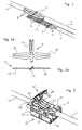
- a main cable 1 with main cable cores 2 is contacted by a sub-cable 3 with sub-cable cores 4.
- the plug contacts are, for example, connected via terminals 7 fixed to the secondary cable cores 4.
- each contacting element 5 has a cutting clamp 11 for contacting the Hautpraitadern and at least one clamping contact 12, in the illustrated embodiment, there are two terminal contacts.
- the contacting element 5 is integrally formed, as a punched out of a sheet metal stamped part.
- the cutters formed on the inner side of the cutting clamp 11 have been sharpened after punching by embossing or grinding.
- the cutting clamp is - in the example drawn by about 45 ° - turned off with respect to the sheet metal plane. This allows a geometry of the branching device as shown in Figure 1, so with parallel to the main cable plug contacts 6. But there are other geometries conceivable, for example. Without wacked disconnect terminal and with the main cable vertically wegphaseden plug contacts, or with divider clamps to another Angle are rotated as 45 ° relative to the sheet plane, for example, at an angle between 45 ° and 90 °.
- the clamping contacts 12 of the contacting element are at least locally flat, so that a plane is defined.
- the clamping contact is formed in the plane similar to a tuning fork with two prongs.
- a clamping action for the plug contacts 6 occurs between the two prongs by spring forces along the plane, similar to a fork contact.
- the terminal contacts may - unlike in the illustrated embodiment - also be rotated relative to the original sheet metal plane.
- the material from which the contacting element is made is, for example, copper or a copper alloy.
- the thickness of the sheet is, for example, between 0.5 mm and 1.2 mm, preferably 0.7 mm to 0.9 mm.
- the width of the tines is chosen so that a desired spring force is produced and is therefore dependent on the sheet thickness of the length of the tines and the material. It is, for example, about 1 mm to 3 mm, preferably about 1.7 mm to 2.4 mm.
- the length of the tines may, for example, be between 12 mm and 25 mm.
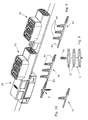
- FIG. 3 shows a view of the components according to FIG. 1, wherein the cable cores of the main cable are guided in a housing base part 21 and wherein also a Besclienselement, namely a Bescariasdeckel 22 is drawn.
- the housing base part has a bushing seat (shown in the figure below) and a main cable core guide (in the figure above) with guide webs 23.
- the contacting elements 5 are fitted in the housing base part, so that the insulation displacement terminals 11 a cable insulation of between the guide webs 23rd Cut through the main lead wires and contact the main wires.
- the wiring cover 22 serves to press down the main cable cores against a resistance sufficiently deep between the guide webs via press ridges 26 so that they are reliably contacted by the insulation displacement clamps 11.
- the wiring cover 22 has pivot axes 24, which are suspended in front indentations 25 of the guide webs, whereupon the wiring cover is pivotally guided about the pivot axes. In an end position of the wiring cover is fixed by locking 27. Also conceivable are wiring covers or wiring means, by means of which pressing or pressing tongs can be connected vertically.
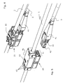
- Figure 4 shows the whole branching system - ie the branching device including the associated plug, wherein the wiring cover 22 is in the end position and wherein the plug 41 is drawn inserted into the socket.
- FIG. 5 shows the branching device 10 as a whole with the plug 41 drawn, including the cover 51.
- the cover has a transparent window 52 which allows a view of the main cable cores. This provides an inspector with the ability to verify the correct routing of the cable wires without opening the cover.
- marks 53 are still provided with ladder names on the window, the correct position of phase, neutral and earth or of other types of cable cores refer.
- the cover can be made as a whole a transparent material, for example, only the window is ground so that a crystal clear view of the cable wires is possible.
- the wiring cover may or may not remain at its end position when the cover is mounted and the branch device is ready for use.
- the illustrated embodiment of the invention includes a latch 42 which is molded on the plug.
- the latch may be present as a separately manufactured example.
- the detent pawl interacts with a latching edge (not visible) present on the socket inner side and causes latching. This can only be solved by a pressing member 44 is pressed against the connector inside, whereby the latch is pushed inward. Due to the molded latch, there are no additional costs for latching during production.
- This principle of the molded on the plug latch can also be used for contacting systems, which are not otherwise configured according to the invention.
- the branching device is intended for three-pole power cables.
- the embodiment of the branching device according to the invention can also be used for other cable systems, for example for two-pole or five-pole power cables, for data cables with any number of cable cores, for loudspeaker cables, etc.
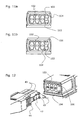
- the embodiment of the inventive branching device according to Figure 6 also has contacting elements and a housing of the type described above. However, it is in contrast to the embodiment of Figures 1 to 5 for standard plug 61 (shown sockets and plugs according to Swiss standard) are formed. This requires some design changes. Thus, the prongs of the terminal contacts must be further spread apart, since the pins 62 of the standard plug are usually round, as shown in Figure 6a . In addition, the contact pins are not arranged at the same height, so that the terminal contacts 12 must be in appropriately adjusted positions. This may mean that the terminal contacts must be mounted offset from each other as shown in the figure.
- FIG. 6b shows an arrangement of three contacting elements, as used in the embodiment according to FIG. This arrangement ensures that the polarity is always the same relative to the plug.
- FIG. 7 shows how, based on the branching device according to the invention, a contacting system can be created without massive structural changes or sophisticated additional parts being necessary.
- the system includes stackable modules 71, wherein the contacting elements 5 engage through contact openings 63, 73 in the respectively adjacent module or the branching device 10 and contact a contacting element 5 of the adjacent module or the branching device.
- the contacting elements can have a contact slot formed in combination as a cutting terminal and plug contact, as illustrated in FIGS . 7a and 7b .
- identical contacting elements can be used.
- the contacts of the modules instead of said contact slots may comprise clamping contacts, which are for example the same design as the already described terminal contacts, but are rotated against them by about 90 °.
- the stackable modules 71 have in the illustrated embodiment still twisting and positioning cam 74 and latching flaps 75 for the attachment of each overlying or underlying module.
- the branching device itself can also be equipped with multiple sockets or sockets. Contacting elements used in these branching devices are then formed, for example, like the contacting element 5 drawn in FIG. 8 with six terminal contacts 12 serving as socket contacts.
- FIG. 1 Another extended contacting system is shown in FIG .
- two series-connected multiple sockets 81 are drawn.
- Each multiple socket has multiple socket contacts, which also have terminal contacts of the type described above and which, for example, are also integrally formed from a sheet metal.
- contacting elements 5 or multiple socket contacts 82 are drawn, as used in the contacting system.
- the multiple socket contacts have a pin portion 83, which, for example. Plate-like and twisted by 90 ° against the original sheet metal plane.
- the pin portion may be made of the stamped part by twisting, or (eg. When punching) be made by pressing.
- the clamping contacts 84 are formed as mentioned analogous to the terminal contacts 12 of the contacting elements 5.
- FIG. 10 also shows a contact 92 for a simpler module of a contacting system with only two sockets compared to FIG. Such a module can also be connected in series with any number of other modules.
- FIGS. 7 to 10 are mere examples for illustrating the various design options which exist due to the contacting elements or multiple socket contacts according to the invention, with very low manufacturing outlay.
- design of contacting or multiple plug contacts with any number of unilaterally or on both sides outwardly projecting terminal contacts arbitrary multiple socket arrangements can be designed.
- a contacting system - according to the type described above or with other types of contacts - is equipped with a multi-stage mechanical coding system.
- Mechanical encodings can prevent a user from mistakenly making connections that are unwanted and that could potentially damage equipment.
- Contacting systems have a basic code which has been factory-set and an individual coding.
- the principle of multi-stage mechanical coding is illustrated in FIGS. 11a and 11b and in FIG .
- the basic coding consists of fixed mechanical features specified in the form of the plugs and sockets, for example notches 43 in the plug or socket, into which combs 102 in the socket or in the plug can be inserted.
- the notches and combs may be present in a manner known per se in various numbers and with different dimensions. They can be made when casting the socket or the plug. They serve, for example, to distinguish between low-voltage, low-voltage or data networks.
- an individual coding is provided.
- the can side guide grooves 103 For the individual Coding of the individual networks are provided on the can side guide grooves 103 with a pin guide 104.
- the plug irreversibly detachable cam 45 are provided, which are inserted when plugging the plug into the grooves. Also reversibly separable elements are conceivable.
- the installer can insert one or more coding pins 106 on the side of the socket and, on the plug side, cut off the corresponding coding sockets, for example with a knife. When inserted coding pin in the arrangement shown in FIG. 12, the plug can only be plugged when the upper cam 45 is removed.
- This procedure allows the use of a contacting system, for example with a branching device according to the invention - in low-voltage, low-voltage or data networks, since different basic coding are possible, and it also offers a cheap, easy way for an additional, individual coding of the plug-in system.
Landscapes
- Connections By Means Of Piercing Elements, Nuts, Or Screws (AREA)
- Massaging Devices (AREA)
- Details Of Connecting Devices For Male And Female Coupling (AREA)
- Connector Housings Or Holding Contact Members (AREA)
- Multi-Conductor Connections (AREA)
- Control Of Driving Devices And Active Controlling Of Vehicle (AREA)
- Paper (AREA)
- Coupling Device And Connection With Printed Circuit (AREA)
Priority Applications (5)
| Application Number | Priority Date | Filing Date | Title |
|---|---|---|---|
| AT04405139T ATE363140T1 (de) | 2004-03-10 | 2004-03-10 | Abzweigvorrichtung |
| DE502004003877T DE502004003877D1 (de) | 2004-03-10 | 2004-03-10 | Abzweigvorrichtung |
| EP04405139A EP1575136B1 (de) | 2004-03-10 | 2004-03-10 | Abzweigvorrichtung |
| PL04405139T PL1575136T3 (pl) | 2004-03-10 | 2004-03-10 | Rozgałęziacz łączy kablowych |
| JP2005057260A JP2005259694A (ja) | 2004-03-10 | 2005-03-02 | 分岐接続装置 |
Applications Claiming Priority (1)
| Application Number | Priority Date | Filing Date | Title |
|---|---|---|---|
| EP04405139A EP1575136B1 (de) | 2004-03-10 | 2004-03-10 | Abzweigvorrichtung |
Publications (3)
| Publication Number | Publication Date |
|---|---|
| EP1575136A2 EP1575136A2 (de) | 2005-09-14 |
| EP1575136A3 EP1575136A3 (de) | 2005-11-23 |
| EP1575136B1 true EP1575136B1 (de) | 2007-05-23 |
Family
ID=34814451
Family Applications (1)
| Application Number | Title | Priority Date | Filing Date |
|---|---|---|---|
| EP04405139A Expired - Lifetime EP1575136B1 (de) | 2004-03-10 | 2004-03-10 | Abzweigvorrichtung |
Country Status (5)
| Country | Link |
|---|---|
| EP (1) | EP1575136B1 (pl) |
| JP (1) | JP2005259694A (pl) |
| AT (1) | ATE363140T1 (pl) |
| DE (1) | DE502004003877D1 (pl) |
| PL (1) | PL1575136T3 (pl) |
Cited By (5)
| Publication number | Priority date | Publication date | Assignee | Title |
|---|---|---|---|---|
| DE202016101373U1 (de) | 2016-03-11 | 2016-03-30 | Phoenix Contact Gmbh & Co. Kg | Elektrisches Kontaktelement für ein Buselement eines Tragschienenbussystems |
| WO2017153531A1 (de) | 2016-03-11 | 2017-09-14 | Phoenix Contact Gmbh & Co. Kg | Elektrisches kontaktelement für ein buselement eines tragschienenbussystems |
| WO2024223650A1 (de) | 2023-04-26 | 2024-10-31 | Wago Verwaltungsgesellschaft Mbh | Abzweigverbinder |
| DE102024100302A1 (de) | 2023-04-26 | 2024-10-31 | WAGO Verwaltungsgesellschaft mit beschränkter Haftung | Abzweigverbinder |
| DE202024106714U1 (de) | 2024-11-21 | 2026-02-24 | WAGO Verwaltungsgesellschaft mit beschränkter Haftung | Elektrisches Gerät |
Families Citing this family (14)
| Publication number | Priority date | Publication date | Assignee | Title |
|---|---|---|---|---|
| TWI338986B (en) | 2006-02-02 | 2011-03-11 | Watlow Electric Mfg | Power controller coupling assemblies |
| DE202009016326U1 (de) * | 2009-12-01 | 2011-04-14 | Weidmüller Interface GmbH & Co. KG | Steckeranordnung |
| US9806445B2 (en) | 2010-01-25 | 2017-10-31 | Enphase Energy, Inc. | Method and apparatus for interconnecting distributed power sources |
| CN102771017B (zh) * | 2010-01-25 | 2015-06-03 | 恩菲斯能源公司 | 使分布式电源互连的方法和设备 |
| AU2011265354C1 (en) * | 2011-12-21 | 2019-08-08 | Kolex Pty Ltd | An electrical connector with insulation displacement contacts |
| DE202013006295U1 (de) | 2013-07-11 | 2013-09-05 | Rosenberger Hochfrequenztechnik Gmbh & Co. Kg | System mit mehreren Steckverbindern und Mehrfachsteckverbinder |
| FR3009900B1 (fr) * | 2013-08-26 | 2016-10-28 | Delphi Tech Holding S A R L | Connecteur electrique pour injecteur de carburant |
| DE202014106058U1 (de) | 2014-12-15 | 2015-01-21 | Erni Production Gmbh & Co. Kg | Steckverbinder |
| CN107768900B (zh) * | 2016-08-23 | 2023-12-22 | 泰科电子(上海)有限公司 | 电连接器 |
| US9774179B1 (en) | 2017-03-30 | 2017-09-26 | Ford Global Technologies, Llc | Fused T-splice wiring |
| JP6920902B2 (ja) * | 2017-06-30 | 2021-08-18 | スリーエム イノベイティブ プロパティズ カンパニー | コネクタ、コネクタアセンブリ及び接触子 |
| CN110679042B (zh) | 2017-08-02 | 2023-01-17 | 阿维科斯公司 | 将第一电线与第二电线连接的设备和方法 |
| US11063375B2 (en) * | 2017-12-06 | 2021-07-13 | Zeon Corporation | Connection instrument |
| DE102019105693A1 (de) * | 2019-03-06 | 2020-09-10 | HARTING Customised Solutions GmbH & Co. KG | Verteilergehäuse |
Family Cites Families (11)
| Publication number | Priority date | Publication date | Assignee | Title |
|---|---|---|---|---|
| AU551468B2 (en) * | 1981-08-14 | 1986-05-01 | H.P.M. Industries Pty Limited | Electrical socket |
| JP3232115B2 (ja) * | 1991-11-26 | 2001-11-26 | 松下電工株式会社 | 防雨形ジョイントボックス |
| JPH08264209A (ja) * | 1995-03-24 | 1996-10-11 | Sumitomo Wiring Syst Ltd | 配電用分岐器 |
| JP3106940B2 (ja) * | 1995-11-07 | 2000-11-06 | 住友電装株式会社 | 圧接コネクタ |
| US5733148A (en) * | 1996-04-04 | 1998-03-31 | The Whitaker Corporation | Electrical connector with programmable keying system |
| DE19706943C2 (de) * | 1997-02-20 | 2000-04-20 | Kostal Leopold Gmbh & Co Kg | Elektrisches Steckkontaktteil |
| US6142817A (en) * | 1997-03-07 | 2000-11-07 | Marconi Communications Inc. | Insulation displacement connector |
| WO1998045896A1 (en) * | 1997-04-10 | 1998-10-15 | The Whitaker Corporation | Power cable tap connector |
| US6045399A (en) * | 1998-11-18 | 2000-04-04 | Yu; Tsung-I | Combination outlet strip |
| PL197279B1 (pl) * | 1998-11-18 | 2008-03-31 | Reichle & De Massari Ag | Urządzenie rozdzielcze |
| JP2001297828A (ja) * | 2000-04-14 | 2001-10-26 | Oki Electric Cable Co Ltd | 逆差し防止用コネクタ |
-
2004
- 2004-03-10 DE DE502004003877T patent/DE502004003877D1/de not_active Expired - Lifetime
- 2004-03-10 EP EP04405139A patent/EP1575136B1/de not_active Expired - Lifetime
- 2004-03-10 PL PL04405139T patent/PL1575136T3/pl unknown
- 2004-03-10 AT AT04405139T patent/ATE363140T1/de active
-
2005
- 2005-03-02 JP JP2005057260A patent/JP2005259694A/ja active Pending
Cited By (6)
| Publication number | Priority date | Publication date | Assignee | Title |
|---|---|---|---|---|
| DE202016101373U1 (de) | 2016-03-11 | 2016-03-30 | Phoenix Contact Gmbh & Co. Kg | Elektrisches Kontaktelement für ein Buselement eines Tragschienenbussystems |
| WO2017153531A1 (de) | 2016-03-11 | 2017-09-14 | Phoenix Contact Gmbh & Co. Kg | Elektrisches kontaktelement für ein buselement eines tragschienenbussystems |
| US10535963B2 (en) | 2016-03-11 | 2020-01-14 | Phoenix Contact Gmbh & Co. Kg | Electrical contact element for a bus element of a mounting rail bus system |
| WO2024223650A1 (de) | 2023-04-26 | 2024-10-31 | Wago Verwaltungsgesellschaft Mbh | Abzweigverbinder |
| DE102024100302A1 (de) | 2023-04-26 | 2024-10-31 | WAGO Verwaltungsgesellschaft mit beschränkter Haftung | Abzweigverbinder |
| DE202024106714U1 (de) | 2024-11-21 | 2026-02-24 | WAGO Verwaltungsgesellschaft mit beschränkter Haftung | Elektrisches Gerät |
Also Published As
| Publication number | Publication date |
|---|---|
| PL1575136T3 (pl) | 2007-12-31 |
| EP1575136A2 (de) | 2005-09-14 |
| ATE363140T1 (de) | 2007-06-15 |
| EP1575136A3 (de) | 2005-11-23 |
| JP2005259694A (ja) | 2005-09-22 |
| DE502004003877D1 (de) | 2007-07-05 |
Similar Documents
| Publication | Publication Date | Title |
|---|---|---|
| EP1575136B1 (de) | Abzweigvorrichtung | |
| EP3324490B1 (de) | Federklemmkontakt zur kontaktierung elektrischer leiter, leiteranschlussklemme und verfahren zur herstellung eines federklemmkontakts | |
| DE102010039244B4 (de) | Schneidklemmverbinder (LSA-Verbinder) mit Kappe | |
| DE69307224T2 (de) | Steckdose von Typ "Modular Jack" mit integrierten Anschlüssen | |
| DE69403428T2 (de) | Elektrischer Verbinder und Anschlusselement dafür zur Verbindung mit ein Messerkontakt | |
| EP0730785A1 (de) | Anschlussklemme für elektrische installationen | |
| CH647895A5 (de) | Elektrischer anschlussteil, verfahren zu dessen verbinden mit einem elektrischen leiter sowie verbinder mit einer mehrzahl von anschlussteilen. | |
| EP3782238B1 (de) | System von geschirmten steckverbindermodulen für modulare industriesteckverbinder | |
| EP3284139A1 (de) | Federklemme | |
| DE102014116490A1 (de) | Anschlussvorrichtung für Mehrleiterkabel | |
| EP0706235A2 (de) | Verriegelbare Flachsteckhülse für eine elektrische Verbindung | |
| EP3005484B1 (de) | Anschluss- oder verbindungsklemme | |
| EP3782235B1 (de) | Direktsteckverbinder | |
| DE1590632A1 (de) | Rastbare elektrische Steckkontaktverbindung | |
| EP2600470B1 (de) | Anschlussvorrichtung für ein Flachbandkabel und elektrisches Gerät mit angeschlossenem Flachbandkabel | |
| EP1523065B1 (de) | Elektrische Klemme | |
| EP1020954B1 (de) | Elektrische Anschlussklemme | |
| EP1154521B1 (de) | Steckverbinder und Verfahren zur Montage eines Steckverbinders | |
| DE102016105192B3 (de) | Leiteranschlussklemme | |
| EP0921611B1 (de) | Netzstromanschlussdose und -schalter | |
| DE102024100302A1 (de) | Abzweigverbinder | |
| DE60313190T2 (de) | Anschlussklemme und Kabelanschlussverbinder | |
| DE19828155A1 (de) | Elektrische Sammelschiene mit einem Anschluß | |
| DE4437791C1 (de) | Kabelsteckverbinder | |
| DE3932346C2 (de) | Elektrischer Steckverbinder |
Legal Events
| Date | Code | Title | Description |
|---|---|---|---|
| PUAI | Public reference made under article 153(3) epc to a published international application that has entered the european phase |
Free format text: ORIGINAL CODE: 0009012 |
|
| AK | Designated contracting states |
Kind code of ref document: A2 Designated state(s): AT BE BG CH CY CZ DE DK EE ES FI FR GB GR HU IE IT LI LU MC NL PL PT RO SE SI SK TR |
|
| AX | Request for extension of the european patent |
Extension state: AL LT LV MK |
|
| PUAL | Search report despatched |
Free format text: ORIGINAL CODE: 0009013 |
|
| AK | Designated contracting states |
Kind code of ref document: A3 Designated state(s): AT BE BG CH CY CZ DE DK EE ES FI FR GB GR HU IE IT LI LU MC NL PL PT RO SE SI SK TR |
|
| AX | Request for extension of the european patent |
Extension state: AL LT LV MK |
|
| 17P | Request for examination filed |
Effective date: 20060130 |
|
| AKX | Designation fees paid |
Designated state(s): AT BE BG CH CY CZ DE DK EE ES FI FR GB GR HU IE IT LI LU MC NL PL PT RO SE SI SK TR |
|
| GRAP | Despatch of communication of intention to grant a patent |
Free format text: ORIGINAL CODE: EPIDOSNIGR1 |
|
| GRAS | Grant fee paid |
Free format text: ORIGINAL CODE: EPIDOSNIGR3 |
|
| GRAA | (expected) grant |
Free format text: ORIGINAL CODE: 0009210 |
|
| AK | Designated contracting states |
Kind code of ref document: B1 Designated state(s): AT BE BG CH CY CZ DE DK EE ES FI FR GB GR HU IE IT LI LU MC NL PL PT RO SE SI SK TR |
|
| PG25 | Lapsed in a contracting state [announced via postgrant information from national office to epo] |
Ref country code: FI Free format text: LAPSE BECAUSE OF FAILURE TO SUBMIT A TRANSLATION OF THE DESCRIPTION OR TO PAY THE FEE WITHIN THE PRESCRIBED TIME-LIMIT Effective date: 20070523 |
|
| REG | Reference to a national code |
Ref country code: GB Ref legal event code: FG4D Free format text: NOT ENGLISH |
|
| REG | Reference to a national code |
Ref country code: CH Ref legal event code: EP |
|
| REG | Reference to a national code |
Ref country code: IE Ref legal event code: FG4D Free format text: LANGUAGE OF EP DOCUMENT: GERMAN |
|
| REF | Corresponds to: |
Ref document number: 502004003877 Country of ref document: DE Date of ref document: 20070705 Kind code of ref document: P |
|
| REG | Reference to a national code |
Ref country code: CH Ref legal event code: NV Representative=s name: FREI PATENTANWALTSBUERO AG |
|
| PG25 | Lapsed in a contracting state [announced via postgrant information from national office to epo] |
Ref country code: SE Free format text: LAPSE BECAUSE OF FAILURE TO SUBMIT A TRANSLATION OF THE DESCRIPTION OR TO PAY THE FEE WITHIN THE PRESCRIBED TIME-LIMIT Effective date: 20070823 |
|
| PG25 | Lapsed in a contracting state [announced via postgrant information from national office to epo] |
Ref country code: ES Free format text: LAPSE BECAUSE OF FAILURE TO SUBMIT A TRANSLATION OF THE DESCRIPTION OR TO PAY THE FEE WITHIN THE PRESCRIBED TIME-LIMIT Effective date: 20070903 |
|
| ET | Fr: translation filed | ||
| GBV | Gb: ep patent (uk) treated as always having been void in accordance with gb section 77(7)/1977 [no translation filed] |
Effective date: 20070523 |
|
| REG | Reference to a national code |
Ref country code: IE Ref legal event code: FD4D |
|
| REG | Reference to a national code |
Ref country code: PL Ref legal event code: T3 |
|
| PG25 | Lapsed in a contracting state [announced via postgrant information from national office to epo] |
Ref country code: DK Free format text: LAPSE BECAUSE OF FAILURE TO SUBMIT A TRANSLATION OF THE DESCRIPTION OR TO PAY THE FEE WITHIN THE PRESCRIBED TIME-LIMIT Effective date: 20070523 Ref country code: CZ Free format text: LAPSE BECAUSE OF FAILURE TO SUBMIT A TRANSLATION OF THE DESCRIPTION OR TO PAY THE FEE WITHIN THE PRESCRIBED TIME-LIMIT Effective date: 20070523 Ref country code: IE Free format text: LAPSE BECAUSE OF FAILURE TO SUBMIT A TRANSLATION OF THE DESCRIPTION OR TO PAY THE FEE WITHIN THE PRESCRIBED TIME-LIMIT Effective date: 20070523 Ref country code: SI Free format text: LAPSE BECAUSE OF FAILURE TO SUBMIT A TRANSLATION OF THE DESCRIPTION OR TO PAY THE FEE WITHIN THE PRESCRIBED TIME-LIMIT Effective date: 20070523 Ref country code: PT Free format text: LAPSE BECAUSE OF FAILURE TO SUBMIT A TRANSLATION OF THE DESCRIPTION OR TO PAY THE FEE WITHIN THE PRESCRIBED TIME-LIMIT Effective date: 20071023 Ref country code: BG Free format text: LAPSE BECAUSE OF FAILURE TO SUBMIT A TRANSLATION OF THE DESCRIPTION OR TO PAY THE FEE WITHIN THE PRESCRIBED TIME-LIMIT Effective date: 20070823 |
|
| PG25 | Lapsed in a contracting state [announced via postgrant information from national office to epo] |
Ref country code: SK Free format text: LAPSE BECAUSE OF FAILURE TO SUBMIT A TRANSLATION OF THE DESCRIPTION OR TO PAY THE FEE WITHIN THE PRESCRIBED TIME-LIMIT Effective date: 20070523 |
|
| PLBE | No opposition filed within time limit |
Free format text: ORIGINAL CODE: 0009261 |
|
| STAA | Information on the status of an ep patent application or granted ep patent |
Free format text: STATUS: NO OPPOSITION FILED WITHIN TIME LIMIT |
|
| 26N | No opposition filed |
Effective date: 20080226 |
|
| PG25 | Lapsed in a contracting state [announced via postgrant information from national office to epo] |
Ref country code: IT Free format text: LAPSE BECAUSE OF FAILURE TO SUBMIT A TRANSLATION OF THE DESCRIPTION OR TO PAY THE FEE WITHIN THE PRESCRIBED TIME-LIMIT Effective date: 20070523 Ref country code: GR Free format text: LAPSE BECAUSE OF FAILURE TO SUBMIT A TRANSLATION OF THE DESCRIPTION OR TO PAY THE FEE WITHIN THE PRESCRIBED TIME-LIMIT Effective date: 20070824 Ref country code: GB Free format text: LAPSE BECAUSE OF FAILURE TO SUBMIT A TRANSLATION OF THE DESCRIPTION OR TO PAY THE FEE WITHIN THE PRESCRIBED TIME-LIMIT Effective date: 20070523 |
|
| PG25 | Lapsed in a contracting state [announced via postgrant information from national office to epo] |
Ref country code: RO Free format text: LAPSE BECAUSE OF FAILURE TO SUBMIT A TRANSLATION OF THE DESCRIPTION OR TO PAY THE FEE WITHIN THE PRESCRIBED TIME-LIMIT Effective date: 20070523 |
|
| BERE | Be: lapsed |
Owner name: REICHLE & DE-MASSARI A.G. Effective date: 20080331 |
|
| PG25 | Lapsed in a contracting state [announced via postgrant information from national office to epo] |
Ref country code: MC Free format text: LAPSE BECAUSE OF NON-PAYMENT OF DUE FEES Effective date: 20080331 |
|
| PG25 | Lapsed in a contracting state [announced via postgrant information from national office to epo] |
Ref country code: EE Free format text: LAPSE BECAUSE OF FAILURE TO SUBMIT A TRANSLATION OF THE DESCRIPTION OR TO PAY THE FEE WITHIN THE PRESCRIBED TIME-LIMIT Effective date: 20070523 |
|
| PG25 | Lapsed in a contracting state [announced via postgrant information from national office to epo] |
Ref country code: BE Free format text: LAPSE BECAUSE OF NON-PAYMENT OF DUE FEES Effective date: 20080331 |
|
| PG25 | Lapsed in a contracting state [announced via postgrant information from national office to epo] |
Ref country code: CY Free format text: LAPSE BECAUSE OF FAILURE TO SUBMIT A TRANSLATION OF THE DESCRIPTION OR TO PAY THE FEE WITHIN THE PRESCRIBED TIME-LIMIT Effective date: 20070523 |
|
| PG25 | Lapsed in a contracting state [announced via postgrant information from national office to epo] |
Ref country code: HU Free format text: LAPSE BECAUSE OF FAILURE TO SUBMIT A TRANSLATION OF THE DESCRIPTION OR TO PAY THE FEE WITHIN THE PRESCRIBED TIME-LIMIT Effective date: 20071124 Ref country code: LU Free format text: LAPSE BECAUSE OF NON-PAYMENT OF DUE FEES Effective date: 20080310 |
|
| PG25 | Lapsed in a contracting state [announced via postgrant information from national office to epo] |
Ref country code: TR Free format text: LAPSE BECAUSE OF FAILURE TO SUBMIT A TRANSLATION OF THE DESCRIPTION OR TO PAY THE FEE WITHIN THE PRESCRIBED TIME-LIMIT Effective date: 20070523 |
|
| REG | Reference to a national code |
Ref country code: CH Ref legal event code: NV Representative=s name: THOMAS DAUB |
|
| REG | Reference to a national code |
Ref country code: DE Ref legal event code: R082 Ref document number: 502004003877 Country of ref document: DE Representative=s name: DAUB UND KOLLEGEN, DE Ref country code: DE Ref legal event code: R082 Ref document number: 502004003877 Country of ref document: DE Representative=s name: PATENT- UND RECHTSANWALTSKANZLEI DAUB, DE |
|
| PGFP | Annual fee paid to national office [announced via postgrant information from national office to epo] |
Ref country code: FR Payment date: 20130408 Year of fee payment: 10 |
|
| PGFP | Annual fee paid to national office [announced via postgrant information from national office to epo] |
Ref country code: NL Payment date: 20130320 Year of fee payment: 10 Ref country code: PL Payment date: 20130301 Year of fee payment: 10 |
|
| REG | Reference to a national code |
Ref country code: NL Ref legal event code: V1 Effective date: 20141001 |
|
| REG | Reference to a national code |
Ref country code: FR Ref legal event code: ST Effective date: 20141128 |
|
| PG25 | Lapsed in a contracting state [announced via postgrant information from national office to epo] |
Ref country code: FR Free format text: LAPSE BECAUSE OF NON-PAYMENT OF DUE FEES Effective date: 20140331 |
|
| PG25 | Lapsed in a contracting state [announced via postgrant information from national office to epo] |
Ref country code: NL Free format text: LAPSE BECAUSE OF NON-PAYMENT OF DUE FEES Effective date: 20141001 |
|
| PG25 | Lapsed in a contracting state [announced via postgrant information from national office to epo] |
Ref country code: PL Free format text: LAPSE BECAUSE OF NON-PAYMENT OF DUE FEES Effective date: 20140310 |
|
| REG | Reference to a national code |
Ref country code: PL Ref legal event code: LAPE |
|
| PGFP | Annual fee paid to national office [announced via postgrant information from national office to epo] |
Ref country code: AT Payment date: 20160322 Year of fee payment: 13 |
|
| REG | Reference to a national code |
Ref country code: CH Ref legal event code: PCAR Free format text: NEW ADDRESS: POSTFACH, 8058 ZUERICH-FLUGHAFEN (CH) |
|
| REG | Reference to a national code |
Ref country code: AT Ref legal event code: MM01 Ref document number: 363140 Country of ref document: AT Kind code of ref document: T Effective date: 20170310 |
|
| PG25 | Lapsed in a contracting state [announced via postgrant information from national office to epo] |
Ref country code: AT Free format text: LAPSE BECAUSE OF NON-PAYMENT OF DUE FEES Effective date: 20170310 |
|
| PGFP | Annual fee paid to national office [announced via postgrant information from national office to epo] |
Ref country code: DE Payment date: 20180322 Year of fee payment: 15 Ref country code: CH Payment date: 20180321 Year of fee payment: 15 |
|
| REG | Reference to a national code |
Ref country code: CH Ref legal event code: PCAR Free format text: NEW ADDRESS: LEUTSCHENBACHSTRASSE 95, 8050 ZUERICH (CH) |
|
| REG | Reference to a national code |
Ref country code: DE Ref legal event code: R119 Ref document number: 502004003877 Country of ref document: DE |
|
| REG | Reference to a national code |
Ref country code: CH Ref legal event code: PL |
|
| PG25 | Lapsed in a contracting state [announced via postgrant information from national office to epo] |
Ref country code: DE Free format text: LAPSE BECAUSE OF NON-PAYMENT OF DUE FEES Effective date: 20191001 Ref country code: CH Free format text: LAPSE BECAUSE OF NON-PAYMENT OF DUE FEES Effective date: 20190331 Ref country code: LI Free format text: LAPSE BECAUSE OF NON-PAYMENT OF DUE FEES Effective date: 20190331 |