EP1575114A2 - Direkt-Methanol-Brennstoffzelle - Google Patents
Direkt-Methanol-Brennstoffzelle Download PDFInfo
- Publication number
- EP1575114A2 EP1575114A2 EP05004861A EP05004861A EP1575114A2 EP 1575114 A2 EP1575114 A2 EP 1575114A2 EP 05004861 A EP05004861 A EP 05004861A EP 05004861 A EP05004861 A EP 05004861A EP 1575114 A2 EP1575114 A2 EP 1575114A2
- Authority
- EP
- European Patent Office
- Prior art keywords
- membrane
- gas diffusion
- cell
- diffusion layer
- catalyst
- Prior art date
- Legal status (The legal status is an assumption and is not a legal conclusion. Google has not performed a legal analysis and makes no representation as to the accuracy of the status listed.)
- Withdrawn
Links
Images


Classifications
-
- H—ELECTRICITY
- H01—ELECTRIC ELEMENTS
- H01M—PROCESSES OR MEANS, e.g. BATTERIES, FOR THE DIRECT CONVERSION OF CHEMICAL ENERGY INTO ELECTRICAL ENERGY
- H01M8/00—Fuel cells; Manufacture thereof
- H01M8/02—Details
- H01M8/0202—Collectors; Separators, e.g. bipolar separators; Interconnectors
- H01M8/023—Porous and characterised by the material
- H01M8/0236—Glass; Ceramics; Cermets
-
- H—ELECTRICITY
- H01—ELECTRIC ELEMENTS
- H01M—PROCESSES OR MEANS, e.g. BATTERIES, FOR THE DIRECT CONVERSION OF CHEMICAL ENERGY INTO ELECTRICAL ENERGY
- H01M8/00—Fuel cells; Manufacture thereof
- H01M8/02—Details
-
- H—ELECTRICITY
- H01—ELECTRIC ELEMENTS
- H01M—PROCESSES OR MEANS, e.g. BATTERIES, FOR THE DIRECT CONVERSION OF CHEMICAL ENERGY INTO ELECTRICAL ENERGY
- H01M4/00—Electrodes
- H01M4/86—Inert electrodes with catalytic activity, e.g. for fuel cells
- H01M4/88—Processes of manufacture
-
- H—ELECTRICITY
- H01—ELECTRIC ELEMENTS
- H01M—PROCESSES OR MEANS, e.g. BATTERIES, FOR THE DIRECT CONVERSION OF CHEMICAL ENERGY INTO ELECTRICAL ENERGY
- H01M8/00—Fuel cells; Manufacture thereof
- H01M8/02—Details
- H01M8/0202—Collectors; Separators, e.g. bipolar separators; Interconnectors
- H01M8/023—Porous and characterised by the material
- H01M8/0239—Organic resins; Organic polymers
-
- H—ELECTRICITY
- H01—ELECTRIC ELEMENTS
- H01M—PROCESSES OR MEANS, e.g. BATTERIES, FOR THE DIRECT CONVERSION OF CHEMICAL ENERGY INTO ELECTRICAL ENERGY
- H01M8/00—Fuel cells; Manufacture thereof
- H01M8/02—Details
- H01M8/0202—Collectors; Separators, e.g. bipolar separators; Interconnectors
- H01M8/023—Porous and characterised by the material
- H01M8/0241—Composites
- H01M8/0245—Composites in the form of layered or coated products
-
- H—ELECTRICITY
- H01—ELECTRIC ELEMENTS
- H01M—PROCESSES OR MEANS, e.g. BATTERIES, FOR THE DIRECT CONVERSION OF CHEMICAL ENERGY INTO ELECTRICAL ENERGY
- H01M8/00—Fuel cells; Manufacture thereof
- H01M8/10—Fuel cells with solid electrolytes
-
- H—ELECTRICITY
- H01—ELECTRIC ELEMENTS
- H01M—PROCESSES OR MEANS, e.g. BATTERIES, FOR THE DIRECT CONVERSION OF CHEMICAL ENERGY INTO ELECTRICAL ENERGY
- H01M8/00—Fuel cells; Manufacture thereof
- H01M8/10—Fuel cells with solid electrolytes
- H01M8/1009—Fuel cells with solid electrolytes with one of the reactants being liquid, solid or liquid-charged
- H01M8/1011—Direct alcohol fuel cells [DAFC], e.g. direct methanol fuel cells [DMFC]
-
- Y—GENERAL TAGGING OF NEW TECHNOLOGICAL DEVELOPMENTS; GENERAL TAGGING OF CROSS-SECTIONAL TECHNOLOGIES SPANNING OVER SEVERAL SECTIONS OF THE IPC; TECHNICAL SUBJECTS COVERED BY FORMER USPC CROSS-REFERENCE ART COLLECTIONS [XRACs] AND DIGESTS
- Y02—TECHNOLOGIES OR APPLICATIONS FOR MITIGATION OR ADAPTATION AGAINST CLIMATE CHANGE
- Y02E—REDUCTION OF GREENHOUSE GAS [GHG] EMISSIONS, RELATED TO ENERGY GENERATION, TRANSMISSION OR DISTRIBUTION
- Y02E60/00—Enabling technologies; Technologies with a potential or indirect contribution to GHG emissions mitigation
- Y02E60/30—Hydrogen technology
- Y02E60/50—Fuel cells
Definitions
- the application is directed to a direct methanol fuel cell (DMFC).
- DMFC direct methanol fuel cell
- the direct methanol fuel cell catalytically oxidizes methanol to generate electricity.
- the DMFC differs from PEM (proton exchange membrane) or solid polymer fuel cells, which use hydrogen gas for generating electricity.
- PEM proto exchange membrane
- One major advantage of the DMFC over the PEM fuel cell is its ability to use methanol, a relatively inexpensive and easily handled material when compared to hydrogen gas.
- One major disadvantage of the DMFC, when compared to the PEM fuel cell is methanol crossover. Methanol crossover occurs when methanol from the anode crosses to the cathode. This causes the loss of efficiency of the cell. Nevertheless, the DMFC appears to be a viable portable power source for devices such as cellular or mobile telephones, and handheld or laptop computers. "Types of Fuel Cells," Fuel Cells 2000, www.fuelcells.org ; Thomas, et al, “Fuel Cells-Green Power,” Los Alamos National Laboratory, LA-VR-99-3231.
- the DMFC is an electrochemical device.
- the anodic catalyzed reaction is: CH 3 OH + H 2 O ⁇ CO 2 + 6H + + 6e -
- the cathodic catalyzed reaction is: 3/2 O 2 + 6H + + 6e - ⁇ 3H 2 O
- the overall cell reaction is: CH 3 OH + 3/2 O 2 ⁇ CO 2 + 2H 2 O
- oxygen typically from air must reach the cathode and water must be removed. If oxygen cannot reach the cathode, efficiency drops because the cathode half cell reaction is impeded. If water, which can be used to moisten the PCM, is allowed to accumulate, it will prevent oxygen from reaching the cathode.
- DMFC is targeted, in part, at a portable power source for cellular or mobile telephones and handheld or laptop computers.
- a DMFC is disclosed.
- the DMFC 40 has proton conducting membrane (PCM) 80 with CO 2 conducting elements 52.
- PCM proton conducting membrane
- the catalyst, anode or cathode is applied to either a surface of the PCM 80 or to the gas diffusion layers 44, 48.
- the respective flow fields are in communication with their respective gas diffusion layers and the combined action of these flow fields and diffusion layers is intended to ensure the even distribution of reactants to the catalyst and the efficient removal of unwanted products, by-products, and unreacted reactants for the reaction.
- the gas diffusion layers are made of carbon fiber paper and/or carbon fiber cloth and may be "wet-proofed" with PTFE polymer. Note that the gas diffusion layer, catalyst, and PCM are in close contact to promote electrons or protons conductivity.
- fuel methanol, methanol/water in either liquid or vapor form
- products water, CO 2 , and unreacted fuel
- CO 2 produced at the anode is intended to cross the PCM 80 via CO 2 conductors 52.
- Water produced at the anode is not meant to remain in the gas diffusion layer 42 as is apparent from the use of the PTFE.
- air the source of O 2
- water, unreacted air, and CO 2 are removed at the other end of flow field 35. Water produced at the cathode is not intended to remain in the gas diffusion layer 48 as is apparent from the use of the PTFE.
- a direct methanol fuel cell has a proton conducting membrane (PCM), a catalyst in contact with the PCM, a gas diffusion layer in contact with the catalyst, and a conducting plate in contact with the gas diffusion membrane.
- the gas diffusion layer comprises a non-metallic microporous membrane.
- the non-metallic microporous membrane may be a microporous membrane, a laminate of a microporous membrane, and a skinned microporous membrane.
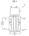
- Figure 1 a direct methanol fuel cell system 10.
- DMFC system 10 includes a DMFC 12, a fuel source 14, and an electrical circuit 16.
- DMFC may include one or more DMFC.
- Fuel source 14 is a storage vessel that contains the fuel, methanol, or a mixture of methanol and water.
- Electrical circuit 16 includes a switch 18 and a load 20.
- Load 20 may be any device that requires electricity, such as a cellular or mobile telephone, or a handheld or laptop computer, or the like.
- Fuel is supplied to DMFC 12 via line 22 from source 14 and is returned to source 14 via line 24 from DMFC 12.
- Air is supplied to DMFC 12 via line 26 and vented from DMFC 12 via line 28.
- DMFC 12 includes a membrane electrode assembly (MEA) 30 preferably sandwiched between a pair of collection plates 32, 34. Collection plates are electrically conductive and are coupled to electrical circuit 16. Collection plate 32 includes a fuel distribution channel 36. One end of channel 36 is in fluid communication with line 22 and the other end of channel 36 is in fluid communication with line 24. Collection plate 34 includes an oxidant distribution channel 38. One end of channel 38 is in fluid communication with line 26 and the other end is in fluid communication with line 28.
- MEA membrane electrode assembly
- channels 36 and 38 The geometry of channels 36 and 38 is such that fuel or oxidant is evenly distributed to the catalysts of the DMFC 12.
- MEA 30 includes a proton conducting membrane (PCM) 40 with an anode catalyst 42 on one side thereof and a cathode catalyst 44 on the other side thereof and all sandwiched between gas diffusion layers 46 and 48.
- PCM 40 is conventional, for example NAFION® from DuPont, Wilmington, DE or the hybrid set forth in WO 02/45196A2, incorporated herein by reference.
- Anode catalyst 42 may be adhered to a face of PCM 40 or adhered to the fiber surfaces of a carbon fiber mat or cloth.
- cathode catalyst 44 may be adhered to the other face of PCM 40 or adhered to fiber surfaces of a carbon fiber mat or cloth.
- the anode and cathode catalyst are conventional and the methods of adhering same are also conventional.
- the gas diffusion layers 46 and 48 may comprise a non-metallic microporous membrane.
- Non-metallic microporous membrane includes a microporous membrane, a laminate of a microporous membrane (e.g., one or more membranes, or membranes and coatings), and a skinned microporous membrane.
- the non-metallic microporous membrane may include a fiber substrate, e.g., a carbon fiber substrate.
- Such membranes may be further characterized as flat sheet membranes having a thickness from 1 to 300 microns.
- the non-metallic microporous membrane may take on several different forms, the ultimate form being dependent upon the desired function of the membrane. Functions of the membrane will be dependent upon whether it is located on the anode side or the cathode side. Functions for membranes at the anode side may include, alone or in combination: allowing the fuel to pass to the catalyst; preventing accumulation of water at the catalyst; removal of water from the catalyst, but not to the fuel source; preventing accumulation of MeOH at the catalyst thereby reducing the chance for methanol crossover, allowing MeOH to return to the fuel source, preventing accumulation of CO 2 at the catalyst. Functions for membranes at the cathode side may include, alone or in combination: removal of unnecessary water; removal of CO 2 .
- Non-metallic membranes suitable to address these functions include polymeric or ceramic microporous or nonporous membranes, skinned membranes, symmetric or asymmetric membranes, single or multi-layered membranes, and combinations thereof.
- Such membranes are known, see for example, Kesting, R., Synthetic Polymeric Membranes, 2nd Edition, John Wiley & Sons, New York, NY (1985), incorporated herein by reference.
- Such membranes can be made of various polymers, for example, polyolefins (e.g., polyethylene, polypropylene, poly-3-methylbutene-1, poly-4-methylpentene-1), vinyl polymers (e.g., polystyrene, poly(methyl methacrylate), fluorine-containing polymers (e.g., polyvinylidene, polyvinyltrimethylsilane, fluorovinylethylene/tetrafluoroethylene copolymer), polyamides (e.g., nylon 6, nylon 66, nylon 12), polyesters (e.g., polyester terphthalate, polybutylene terephthalate, polyethylene-2,6-naphthalate), polycarbonates (e.g., poly-4,4'-dihydroxydiphenyl-2,2-propane carbonate), polyethers (e.g., polyoxymethylene, polymethylene sulfide), polyphenylene chalcogenides (e.g., polythioether, poly
- Asymmetric membranes include membranes with diameters that vary from one surface to another (e.g., pores with decreasing diameters from one surface of the membranes to the other; pores with decreasing diameters from one surface to a point between the membrane surfaces and increasing diameters to the opposite surface; pores with increasing diameters from one surface to a point between the membrane surfaces and decreasing diameters to the opposite surface).
- Skinned microporous membranes include microporous membranes, symmetric or asymmetric, that have at least one "dense" gas separation layer.
- this dense layer is located at one or both of the membrane's surfaces, but may be located within the membrane's interior (i.e., between the surfaces). Additionally, the dense layer may be hydrophobic or hydrophilic.
- the dense layer may be characterized as non-porous, but may include nanopores.
- the dense layer may have a gas selectivity, i.e., the ability to diffuse one material preferentially over another.
- Exemplary dense layers may have O 2 /N 2 gas selectivities of 1.2 or greater or 2.0 or greater.
- Exemplary dense layers may have CO 2 /N 2 selectivities of 6.0 or greater or 8.0 or greater.
- the membranes may have functional coatings/additives, for example, hydrophobic or hydrophilic materials. Such materials are conventional.
- the membranes may also include perm-selective gels or polymers that preferably pass one or more of the reactants, products, or by-products. Such perm-selective gels or polymers are conventional. Such a perm-selective material could, for example, coat one or more sides of the membrane or be sandwiched between membranes.
- an asymmetric membrane pores with decreasing diameters from one surface of the membranes to the other
- This membrane which could be used at either the anode or cathode, would be placed in the MEA with the coated face toward the PCM. Thereby, water, a reactant at the anode and a product at the cathode, and retained around the PCM, is available to moisten the PCM so that its proton conductivity is maintained.
- asymmetric membranes By way of further example of asymmetric membranes reference is made to U.S. Patent No. 4,664,681 which discusses asymmetric membranes, incorporated herein by reference. Such membranes can be made of various polymers, note the list of polymers set forth above. These membranes are further characterized as having an apparent oxygen permeability coefficient at room temperature (25°C) that is at least 3 times greater than the apparent oxygen permeability coefficient (@25°C) for the corresponding homogeneous (symmetrical) membrane, and having an oxygen-nitrogen separation coefficient (@25°C) of at least 1.2.
- FIGs 2, 3, and 4 photomicrographs of a PMP (polymethylpentene) asymmetric membrane.
- Figures 2 - 4 illustrate an asymmetric membrane having pores that have decreasing diameters from one surface to the other.
- the surface having large pores is illustrated.
- Figure 3 the surface with small pores is illustrated.
- Figure 4 is a cross-sectional view of the membrane with the large pore side at the bottom and the small pore side at the top.
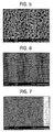
- FIGs 5, 6, and 7 photomicrographs of a PMP (polymethylpentene) skinned membrane.
- Figures 5 - 7 illustrate skinned membrane having pores that have decreasing diameters from one surface to no pores at the other.
- the surface having large pores is illustrated.
- Figure 6 the surface with no pores is illustrated.
- Figure 7 is a cross-sectional view of part of the membrane with the dense layer at the right.
- FIGs 8 and 9 illustrate further embodiments of the invention.
- a plurality of DMFC's are joined together to form a stack 50.
- the DMFC's 12 are joined in series.
- the DMFC's 12 are joined in parallel.
Landscapes
- Chemical & Material Sciences (AREA)
- Engineering & Computer Science (AREA)
- Chemical Kinetics & Catalysis (AREA)
- Manufacturing & Machinery (AREA)
- General Chemical & Material Sciences (AREA)
- Electrochemistry (AREA)
- Sustainable Development (AREA)
- Sustainable Energy (AREA)
- Life Sciences & Earth Sciences (AREA)
- Composite Materials (AREA)
- Ceramic Engineering (AREA)
- Fuel Cell (AREA)
- Inert Electrodes (AREA)
Applications Claiming Priority (4)
| Application Number | Priority Date | Filing Date | Title |
|---|---|---|---|
| US798032 | 1985-11-14 | ||
| US10/798,032 US20050202306A1 (en) | 2004-03-11 | 2004-03-11 | Direct methanol fuel cell |
| US974490 | 2004-10-27 | ||
| US10/974,490 US7547486B2 (en) | 2004-03-11 | 2004-10-27 | Direct methanol fuel cell |
Publications (1)
| Publication Number | Publication Date |
|---|---|
| EP1575114A2 true EP1575114A2 (de) | 2005-09-14 |
Family
ID=34830630
Family Applications (1)
| Application Number | Title | Priority Date | Filing Date |
|---|---|---|---|
| EP05004861A Withdrawn EP1575114A2 (de) | 2004-03-11 | 2005-03-05 | Direkt-Methanol-Brennstoffzelle |
Country Status (7)
| Country | Link |
|---|---|
| EP (1) | EP1575114A2 (de) |
| JP (1) | JP4406616B2 (de) |
| KR (1) | KR100778963B1 (de) |
| CN (1) | CN1667861A (de) |
| CA (1) | CA2499104A1 (de) |
| SG (1) | SG115756A1 (de) |
| TW (1) | TWI266447B (de) |
Cited By (5)
| Publication number | Priority date | Publication date | Assignee | Title |
|---|---|---|---|---|
| WO2007061522A2 (en) | 2005-11-21 | 2007-05-31 | Relion, Inc. | Proton exchange membrane fuel cell and method of forming a fuel cell |
| US7811359B2 (en) | 2007-01-18 | 2010-10-12 | General Electric Company | Composite membrane for separation of carbon dioxide |
| US8597846B2 (en) | 2007-05-08 | 2013-12-03 | Relion, Inc. | Proton exchange membrane fuel cell stack and fuel cell stack module |
| US9293778B2 (en) | 2007-06-11 | 2016-03-22 | Emergent Power Inc. | Proton exchange membrane fuel cell |
| WO2022075850A1 (en) | 2020-10-09 | 2022-04-14 | Nederlandse Organisatie Voor Toegepast-Natuurwetenschappelijk Onderzoek Tno | Gas diffusion layer for electrochemically converting gas |
Families Citing this family (4)
| Publication number | Priority date | Publication date | Assignee | Title |
|---|---|---|---|---|
| JP5118372B2 (ja) * | 2007-03-28 | 2013-01-16 | 株式会社東芝 | 直接メタノール型燃料電池 |
| KR101499731B1 (ko) * | 2008-11-24 | 2015-03-09 | 광주과학기술원 | 고분자 전해질막, 고분자 전해질막의 제조방법 및 고분자 전해질막을 구비하는 막-전극 접합체 |
| CN102832405B (zh) * | 2012-08-31 | 2015-04-15 | 清华大学 | 一种基于非磺酸基亲水纳米孔道聚合物膜的燃料电池及其制备方法 |
| CN109167089B (zh) * | 2018-09-30 | 2020-09-29 | 德州新动能铁塔发电有限公司 | 传质性改善的膜电极及其制备方法 |
Family Cites Families (1)
| Publication number | Priority date | Publication date | Assignee | Title |
|---|---|---|---|---|
| US6733915B2 (en) * | 2001-12-27 | 2004-05-11 | E. I. Du Pont De Nemours And Company | Gas diffusion backing for fuel cells |
-
2005
- 2005-03-01 CA CA002499104A patent/CA2499104A1/en not_active Abandoned
- 2005-03-05 EP EP05004861A patent/EP1575114A2/de not_active Withdrawn
- 2005-03-07 TW TW094106788A patent/TWI266447B/zh not_active IP Right Cessation
- 2005-03-09 KR KR1020050019490A patent/KR100778963B1/ko not_active Expired - Fee Related
- 2005-03-10 JP JP2005066594A patent/JP4406616B2/ja not_active Expired - Fee Related
- 2005-03-11 CN CNA2005100545625A patent/CN1667861A/zh active Pending
- 2005-03-11 SG SG200501528A patent/SG115756A1/en unknown
Cited By (6)
| Publication number | Priority date | Publication date | Assignee | Title |
|---|---|---|---|---|
| WO2007061522A2 (en) | 2005-11-21 | 2007-05-31 | Relion, Inc. | Proton exchange membrane fuel cell and method of forming a fuel cell |
| EP1952464A4 (de) * | 2005-11-21 | 2013-01-16 | Relion Inc | Protonenaustauschmembran-brennstoffzelle und verfahren zur bildung einer brennstoffzelle |
| US7811359B2 (en) | 2007-01-18 | 2010-10-12 | General Electric Company | Composite membrane for separation of carbon dioxide |
| US8597846B2 (en) | 2007-05-08 | 2013-12-03 | Relion, Inc. | Proton exchange membrane fuel cell stack and fuel cell stack module |
| US9293778B2 (en) | 2007-06-11 | 2016-03-22 | Emergent Power Inc. | Proton exchange membrane fuel cell |
| WO2022075850A1 (en) | 2020-10-09 | 2022-04-14 | Nederlandse Organisatie Voor Toegepast-Natuurwetenschappelijk Onderzoek Tno | Gas diffusion layer for electrochemically converting gas |
Also Published As
| Publication number | Publication date |
|---|---|
| KR20060043569A (ko) | 2006-05-15 |
| TW200541148A (en) | 2005-12-16 |
| JP4406616B2 (ja) | 2010-02-03 |
| CN1667861A (zh) | 2005-09-14 |
| JP2005259700A (ja) | 2005-09-22 |
| TWI266447B (en) | 2006-11-11 |
| KR100778963B1 (ko) | 2007-11-28 |
| SG115756A1 (en) | 2005-10-28 |
| CA2499104A1 (en) | 2005-09-11 |
Similar Documents
| Publication | Publication Date | Title |
|---|---|---|
| EP1575114A2 (de) | Direkt-Methanol-Brennstoffzelle | |
| JPWO2007123066A1 (ja) | 固体高分子型燃料電池 | |
| US20030186107A1 (en) | High performance fuel cells | |
| KR100796886B1 (ko) | 직접산화형 연료전지 및 직접산화형 연료전지 시스템의운전방법 | |
| US7547486B2 (en) | Direct methanol fuel cell | |
| KR100717790B1 (ko) | 연료 전지용 막-전극 어셈블리 및 이를 포함하는 연료 전지시스템. | |
| CN1988237B (zh) | 直接型燃料电池和直接型燃料电池系统 | |
| JP2006049115A (ja) | 燃料電池 | |
| KR101147238B1 (ko) | 연료 전지 시스템 및 그 스택 | |
| JP4348154B2 (ja) | 固体高分子型燃料電池用触媒膜、その製造方法及びそれを用いた燃料電池 | |
| JP2006024401A (ja) | 燃料電池 | |
| JP2006294603A (ja) | 直接型燃料電池 | |
| US20090263698A1 (en) | Fuel cell system and fuel cell | |
| US20060046126A1 (en) | Fuel cell and information terminal carrying the same | |
| CN100405647C (zh) | 直接型燃料电池 | |
| JP4660151B2 (ja) | 燃料電池 | |
| JP2005268176A (ja) | 燃料電池 | |
| JP2000173634A (ja) | 燃料電池 | |
| JPWO2012001839A1 (ja) | 直接酸化型燃料電池システム | |
| KR20090039423A (ko) | 연료전지용 막-전극 어셈블리 및 이를 포함하는 연료전지시스템 | |
| KR20070014621A (ko) | 직접 산화형 연료 전지용 막-전극 어셈블리 및 이를포함하는 직접 산화형 연료 전지 시스템 | |
| CN100463277C (zh) | 包括汽相燃料供应设备的燃料电池系统 | |
| JP3946228B2 (ja) | 燃料電池 | |
| KR101065376B1 (ko) | 연료 전지 시스템, 이에 사용되는 스택 및 세퍼레이터 | |
| KR20070014620A (ko) | 연료 전지용 막-전극 어셈블리, 이를 포함하는 연료 전지시스템 |
Legal Events
| Date | Code | Title | Description |
|---|---|---|---|
| PUAI | Public reference made under article 153(3) epc to a published international application that has entered the european phase |
Free format text: ORIGINAL CODE: 0009012 |
|
| AK | Designated contracting states |
Kind code of ref document: A2 Designated state(s): AT BE BG CH CY CZ DE DK EE ES FI FR GB GR HU IE IS IT LI LT LU MC NL PL PT RO SE SI SK TR |
|
| AX | Request for extension of the european patent |
Extension state: AL BA HR LV MK YU |
|
| STAA | Information on the status of an ep patent application or granted ep patent |
Free format text: STATUS: THE APPLICATION HAS BEEN WITHDRAWN |
|
| 18W | Application withdrawn |
Effective date: 20060510 |