EP1574752A2 - Kugelspindel - Google Patents
Kugelspindel Download PDFInfo
- Publication number
- EP1574752A2 EP1574752A2 EP05005120A EP05005120A EP1574752A2 EP 1574752 A2 EP1574752 A2 EP 1574752A2 EP 05005120 A EP05005120 A EP 05005120A EP 05005120 A EP05005120 A EP 05005120A EP 1574752 A2 EP1574752 A2 EP 1574752A2
- Authority
- EP
- European Patent Office
- Prior art keywords
- screw
- ball
- groove
- screw groove
- ball screw
- Prior art date
- Legal status (The legal status is an assumption and is not a legal conclusion. Google has not performed a legal analysis and makes no representation as to the accuracy of the status listed.)
- Granted
Links
Images

Classifications
-
- F—MECHANICAL ENGINEERING; LIGHTING; HEATING; WEAPONS; BLASTING
- F16—ENGINEERING ELEMENTS AND UNITS; GENERAL MEASURES FOR PRODUCING AND MAINTAINING EFFECTIVE FUNCTIONING OF MACHINES OR INSTALLATIONS; THERMAL INSULATION IN GENERAL
- F16H—GEARING
- F16H25/00—Gearings comprising primarily only cams, cam-followers and screw-and-nut mechanisms
- F16H25/18—Gearings comprising primarily only cams, cam-followers and screw-and-nut mechanisms for conveying or interconverting oscillating or reciprocating motions
- F16H25/20—Screw mechanisms
- F16H25/22—Screw mechanisms with balls, rollers, or similar members between the co-operating parts; Elements essential to the use of such members
- F16H25/2204—Screw mechanisms with balls, rollers, or similar members between the co-operating parts; Elements essential to the use of such members with balls
- F16H2025/2242—Thread profile of the screw or nut showing a pointed "gothic" arch in cross-section
Definitions
- the present invention relates to a ball screw used for various machine tools such as an electrical discharge machine, a tapping center etc. a motor driven power steering in a motor vehicle, and actuators etc. and more particularly to a ball screw in which the frictional efficiency in its actuation is improved.
- the ball screw comprises a screw shaft formed with a helical screw groove on its outer circumferential surface, a nut fitted on the screw shaft and formed with a helical screw groove on its inner circumferential surface, a plurality of balls contained within a rolling contact passage formed by oppositely arranged screw grooves, and a circulating member forming a circumferentially connecting passage of the rolling contact passage, and is used for example in a motion converting mechanism in which the screw shaft is linearly moved by rotating the nut.
- the ball screw includes different types of ball circulating mechanisms and one of which is a "bridge" or piece type.
- the bridge type ball screw has a connecting passage of screw groove and a "bridge” or piece member for circulation forming a circularly connecting passage of the rolling contact passage is mounted on the nut.
- the bridge type ball screw advantages in a relatively simple and compact structure.
- the ball screw of this type exhibits stable operational characteristics relative to an axial load along the screw shaft applied to the nut as well as a torque applied to the screw shaft if the ball screw is manufactured with a high accuracy.
- the rolling friction resistance would be varied since errors in a radius of curvature of the circular groove of the ball screw and a lead of the helical screw groove etc. are combined. This would cause reduction of a positioning accuracy and controllability of the ball screw or heat generation due to friction which would in turn reduce the life of the ball screw.
- the ball screw 51 has a screw shaft "S”, a nut “N” and a plurality of balls 52.
- the screw shaft “S” is formed with a helical screw groove 55 on its outer circumferential surface 53 and the nut “N” is formed with a helical screw groove 56 on its inner circumferential surface and these helical screw grooves 55 and 56 are oppositely arranged.
- the balls 52 are in rolling contact with the helical screw grooves 55 and 56.
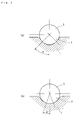
- Each of the screw shaft groove 55 and the nut groove 56 has a Gothic arc cross-sectional configuration. If denoting a radius of the ball 52 by “r”; radii of curvature of first circular arcs 55a and 55b forming parts of cross-section of the screw shaft groove 55 by “Rs1” and “Rs2” respectively; distances between a line “B” passing through the center “A” of the ball 52 and perpendicular to the screw shaft "S” and centers “Cs1” and “Cs2” of the radii of curvature “Rs1” and “Rs2" of the first circular arcs "55a” and “55b” by “Xcs1” and “Xcs2” respectively; radii of curvature of second circular arcs 56a and 56b forming parts of cross-section of the nut groove 56 by “Rn1” and “Rn2” respectively; distances between a line “B” passing through the center "A” of the ball 52 and perpendicular to
- an object of the present invention to provide a ball screw which has a high operational efficiency both in the positive and negative operations and a low mechanical loss.
- a ball screw comprising a screw shaft formed with a helical screw groove on its outer circumferential surface, a nut fitted on the screw shaft and formed with a helical screw groove on its inner circumferential surface, a plurality of balls contained within a rolling contact passage formed by oppositely arranged screw grooves, and a circulating member forming a circumferentially connecting passage of the rolling contact passage characterized in that a ratio "t/d" of the depth "t" of screw groove of the screw shaft to the ball diameter "d” is set at a range 0.20 ⁇ 0.30.
- the ratio "t/d" of the depth "t" of screw groove of the screw shaft to the ball diameter "d” is at a range 0.20 ⁇ 0.30, it is possible to provide a ball screw which can reduce the general mechanical loss and has a high operational efficiency both in the positive and negative operations. Thus it is also possible to improve the accuracy in the positioning of the ball screw and controllability thereof and to reduce heat generation due to friction and thus the life of the ball screw.
- said circulating member comprises a bridge member having a connecting groove for connecting the screw groove of screw shaft by a distance of one circumferential length between adjacent screw grooves, it is possible to reduce the frictional resistance when the balls travel to the bridge member passing over a distance of one circumferential length and thus to reduce the mechanical loss of the ball screw.
- an initial contact angle between the ball and the screw groove is set at a range 25 ⁇ 40°, it is possible to prevent the contact ellipse of the ball from riding across a shoulder of the screw groove as well as to prevent the reduction of a load capacity.
- said screw groove of screw shaft may be formed by rolling. According to the ball screw of the present invention, since the depth of the screw groove is formed smaller than that of the conventional screw groove, it is possible to improve the productivity of the ball screw and thus to reduce its manufacturing cost.
- the surface of screw groove is superfinished so that its surface roughness "Ra" is less than 0.1 and its undulation in rolling movement direction is less than 2 ⁇ m, it is possible not only to obtain a desirable surface roughness but to improve the roundness at the contact point of the screw groove and the ball and thus its undulation components and accordingly to further improve the operational efficiency of the ball screw as well to reduce the coefficient of friction.
- the ball screw of the present invention comprises a screw shaft formed with a helical screw groove on its outer circumferential surface, a nut fitted on the screw shaft and formed with a helical screw groove on its inner circumferential surface, a plurality of balls contained within a rolling contact passage formed by oppositely arranged screw grooves, and a circulating member forming a circumferentially connecting passage of the rolling contact passage, and is characterized in that a ratio "t/d" of the depth "t" of screw groove of the screw shaft to the ball diameter "d” is set at a range 0.20 ⁇ 0.30. Accordingly, it is possible to provide a ball screw which can reduce the general mechanical loss and has a high operational efficiency both in the positive and negative operations. Thus it is also possible to improve the accuracy in the positioning of the ball screw and controllability thereof and to reduce heat generation due to friction and thus the life of the ball screw.
- the best mode for carrying out the present invention is a ball screw comprising a screw shaft formed with a helical screw groove on its outer circumferential surface, a nut fitted on the screw shaft and formed with a helical screw groove on its inner circumferential surface, a plurality of balls contained within a rolling contact passage formed by oppositely arranged screw grooves, and a circulating member forming a circumferentially connecting passage of the rolling contact passage characterized in that a ratio "t/d" of the depth "t" of screw groove of the screw shaft to the ball diameter "d" is set at a range 0.20 ⁇ 0.30 and in an initial contact angle ⁇ between the ball and the screw groove is set at a range 25 ⁇ 40°.
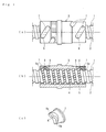
- FIG. 1 shows one preferred embodiment of a ball screw of the present invention wherein Fig. 1(a) is a plan view and Fig. 1 (b) is a longitudinal section view thereof, and Fig. 1 (c) is a perspective view of a bridge member forming a circulating member used in the ball screw of the present invention.
- a screw shaft 1 is formed with a helical screw groove 2 on its outer circumferential surface
- a nut 3 fitted on the screw shaft 1 is formed with a helical screw groove 4 on its inner circumferential surface.
- a plurality of balls 5 are contained between the screw grooves 2 and 4.
- a barrel of the nut 3 is formed with elliptic bridge windows 6 each passing through the wall of nut 3 and cutting out a portion of the screw groove 4.
- Each bridge window 6 is fitted with an elliptic bridge member 7.
- a connecting groove 8 for connecting the screw groove 4 of nut 3 by a distance of one circumferential length between adjacent screw grooves 4 is formed on the inner circumferential surface of the bridge member so that a rolling contact passage of balls 5 is formed by the connecting groove 8 and a portion of substantially one circumferential length of the screw groove 4.
- the plurality of balls 5 contained in the rolling contact passage formed by the screw grooves 2 and 4 roll along the screw grooves 2 and 4, then are guided into the connecting groove 8 of the bridge member 7, and finally return to an adjacent screw groove 4 riding across the screw thread of the screw shaft 1 and continue rolling motion along the screw grooves 2 and 4.
- the connecting groove 8 of the bridge member 7 is formed as having a "S" shaped configuration so as to smoothly connect mutually adjacent screw grooves 4 of the nut 3.
- the connecting groove 8 of the bridge member 7 is connected to the screw groove 4 so that opened edges 8a at opposite ends of the connecting groove 8 correspond to adjacently arranged opened edge 6a of the screw groove 4 of the nut 3.
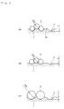
- the balls 5 ride across a land 2a between the screw grooves 2 and 2 when the balls 5 are circulated passing through the connecting groove 8 of the bridging member 7 as shown in Fig. 2.
- the ball screw of the prior art has a ratio "t/d" of the depth "t" of the screw groove 2 relative to the diameter "d" of a ball 5 is set at a range 0.36 ⁇ 0.38.
- the ratio (t/d) is set at a range 0.20 ⁇ 0.30 and various experiments were carried out.
- the depth "t" of the screw groove 2 relative to the ball diameter "d” is set smaller than that of the ball screw of the prior art, it is possible to achieve a higher productivity and a low manufacturing cost when forming the screw groove 2 by rolling.
- the coefficient of friction of the ball screw can be remarkably reduced by superfinishing the surface of the screw groove 2. This is because that the superfinishing enables not only to obtain a superior surface roughness "Ra” less than 1.0 ⁇ m as compared to 1.5 ⁇ 2.0 ⁇ m in the prior art but to improve the roundness at the contact point of the screw groove and the ball and thus its undulation components.
- the screw groove 2 may be formed in any configuration such as a circular arc circular contacting with the ball 5 other than the gothic arc configuration.
- the present invention can provide a ball screw which can reduce whole mechanical loss in the ball screw of high efficiency either in the positive and negative efficiency by setting the ratio "t/d" smaller than that of the prior art. Accordingly it is also possible to improve the accuracy in the positioning of the ball screw and controllability thereof and to reduce heat generation due to friction and thus the life of the ball screw.
- the ball screw according to the present invention can be applied to a motor driven power steering for motor vehicle etc. in which positive and negative operations might be caused during its use.
- the circulating member is not limited to the bridge member and can be formed by a return tube, an end plate etc.
Landscapes
- Engineering & Computer Science (AREA)
- General Engineering & Computer Science (AREA)
- Mechanical Engineering (AREA)
- Transmission Devices (AREA)
Applications Claiming Priority (2)
| Application Number | Priority Date | Filing Date | Title |
|---|---|---|---|
| JP2004068550A JP4744089B2 (ja) | 2004-03-11 | 2004-03-11 | 駒式ボールねじ |
| JP2004068550 | 2004-03-11 |
Publications (3)
| Publication Number | Publication Date |
|---|---|
| EP1574752A2 true EP1574752A2 (de) | 2005-09-14 |
| EP1574752A3 EP1574752A3 (de) | 2006-09-20 |
| EP1574752B1 EP1574752B1 (de) | 2009-05-06 |
Family
ID=34824598
Family Applications (1)
| Application Number | Title | Priority Date | Filing Date |
|---|---|---|---|
| EP20050005120 Expired - Lifetime EP1574752B1 (de) | 2004-03-11 | 2005-03-09 | Kugelspindel |
Country Status (3)
| Country | Link |
|---|---|
| EP (1) | EP1574752B1 (de) |
| JP (1) | JP4744089B2 (de) |
| DE (1) | DE602005014300D1 (de) |
Cited By (1)
| Publication number | Priority date | Publication date | Assignee | Title |
|---|---|---|---|---|
| USD755619S1 (en) * | 2015-01-30 | 2016-05-10 | Kuroda Precision Industries Ltd. | Ball screw |
Families Citing this family (3)
| Publication number | Priority date | Publication date | Assignee | Title |
|---|---|---|---|---|
| JP2009103228A (ja) * | 2007-10-24 | 2009-05-14 | Jtekt Corp | ボールスプライン付きボールねじ |
| JP5117946B2 (ja) * | 2008-07-10 | 2013-01-16 | Ntn株式会社 | ボールねじ |
| CN107477158B (zh) * | 2017-08-31 | 2019-07-12 | 北京精密机电控制设备研究所 | 一种重载滚珠丝杠副滚道结构 |
Family Cites Families (11)
| Publication number | Priority date | Publication date | Assignee | Title |
|---|---|---|---|---|
| US3924486A (en) * | 1973-10-29 | 1975-12-09 | Tech Integrale | Screw and nut transmission mechanism |
| DE2544755C3 (de) * | 1975-10-07 | 1982-01-07 | Korthaus, Helmut, 5600 Wuppertal | Kugelgewindetrieb |
| JPS5252071A (en) * | 1975-10-07 | 1977-04-26 | Buiruke Rihiaruto | Spindleenut apparatus |
| DE3372009D1 (en) * | 1982-03-30 | 1987-07-16 | Shuton Sa | Ball-screw rack device |
| JPH0171263U (de) * | 1987-10-30 | 1989-05-12 | ||
| JP2881855B2 (ja) * | 1989-11-07 | 1999-04-12 | 日本精工株式会社 | ゴシック・アーク溝の超仕上方法 |
| JP3325679B2 (ja) * | 1993-12-10 | 2002-09-17 | 日本精工株式会社 | ボールねじのボール溝形状 |
| JP3675129B2 (ja) * | 1996-09-30 | 2005-07-27 | 日本精工株式会社 | ボールねじ |
| JP4162070B2 (ja) * | 1999-11-10 | 2008-10-08 | 学校法人東海大学 | ボールネジの製造装置及び製造方法 |
| JP2002276765A (ja) * | 2001-03-21 | 2002-09-25 | Ntn Corp | ダブルナット予圧式ボールねじ |
| US6955468B2 (en) * | 2001-11-08 | 2005-10-18 | Nsk.Ltd. | Linear-motion device and ball screw |
-
2004
- 2004-03-11 JP JP2004068550A patent/JP4744089B2/ja not_active Expired - Lifetime
-
2005
- 2005-03-09 DE DE200560014300 patent/DE602005014300D1/de not_active Expired - Lifetime
- 2005-03-09 EP EP20050005120 patent/EP1574752B1/de not_active Expired - Lifetime
Cited By (1)
| Publication number | Priority date | Publication date | Assignee | Title |
|---|---|---|---|---|
| USD755619S1 (en) * | 2015-01-30 | 2016-05-10 | Kuroda Precision Industries Ltd. | Ball screw |
Also Published As
| Publication number | Publication date |
|---|---|
| JP2005256937A (ja) | 2005-09-22 |
| EP1574752B1 (de) | 2009-05-06 |
| EP1574752A3 (de) | 2006-09-20 |
| DE602005014300D1 (de) | 2009-06-18 |
| JP4744089B2 (ja) | 2011-08-10 |
Similar Documents
| Publication | Publication Date | Title |
|---|---|---|
| EP1734285B1 (de) | Kugelgewindetrieb | |
| US6299543B1 (en) | Plunging type constant velocity joint | |
| US5106343A (en) | Constant velocity joint | |
| TWI390129B (zh) | Ball screw device | |
| CN101606001A (zh) | 等速万向接头 | |
| US20070209465A1 (en) | Screw Device And Method Of Manufacturing The Same | |
| EP2072847B1 (de) | Kardangelenk | |
| EP1574752A2 (de) | Kugelspindel | |
| CN108757871B (zh) | 滚珠丝杠副 | |
| JP2002206617A (ja) | ボールねじ | |
| CN113007313B (zh) | 一种高效啮合蜗轮 | |
| JP5004312B2 (ja) | 駒式ボールねじ | |
| WO2021210307A1 (ja) | ボールねじ装置 | |
| US11680628B2 (en) | Ball screw device | |
| US20060248974A1 (en) | Rolling-element screw drive with deflection element | |
| US12429095B2 (en) | Plunging-type constant velocity universal joint | |
| KR20060103256A (ko) | 롤러 나사 | |
| KR102517733B1 (ko) | 등속 조인트 | |
| CN223483332U (zh) | 一种凸圆弧丝杠副 | |
| WO2008075541A1 (ja) | ナット部材における可動体連結構造 | |
| EP0208017A2 (de) | Endlos-Schraubgetriebe zur Bewegungsübertragung | |
| CN214788877U (zh) | 直线保持器及滚珠花键装置 | |
| CN108916341B (zh) | 一种柔性钢球换向循环装置 | |
| US20080173117A1 (en) | Ball screw device | |
| CN101087967A (zh) | 滚珠螺杆 |
Legal Events
| Date | Code | Title | Description |
|---|---|---|---|
| PUAI | Public reference made under article 153(3) epc to a published international application that has entered the european phase |
Free format text: ORIGINAL CODE: 0009012 |
|
| AK | Designated contracting states |
Kind code of ref document: A2 Designated state(s): AT BE BG CH CY CZ DE DK EE ES FI FR GB GR HU IE IS IT LI LT LU MC NL PL PT RO SE SI SK TR |
|
| AX | Request for extension of the european patent |
Extension state: AL BA HR LV MK YU |
|
| PUAL | Search report despatched |
Free format text: ORIGINAL CODE: 0009013 |
|
| AK | Designated contracting states |
Kind code of ref document: A3 Designated state(s): AT BE BG CH CY CZ DE DK EE ES FI FR GB GR HU IE IS IT LI LT LU MC NL PL PT RO SE SI SK TR |
|
| AX | Request for extension of the european patent |
Extension state: AL BA HR LV MK YU |
|
| 17P | Request for examination filed |
Effective date: 20070116 |
|
| AKX | Designation fees paid |
Designated state(s): DE |
|
| 17Q | First examination report despatched |
Effective date: 20071023 |
|
| GRAP | Despatch of communication of intention to grant a patent |
Free format text: ORIGINAL CODE: EPIDOSNIGR1 |
|
| GRAP | Despatch of communication of intention to grant a patent |
Free format text: ORIGINAL CODE: EPIDOSNIGR1 |
|
| GRAS | Grant fee paid |
Free format text: ORIGINAL CODE: EPIDOSNIGR3 |
|
| GRAA | (expected) grant |
Free format text: ORIGINAL CODE: 0009210 |
|
| AK | Designated contracting states |
Kind code of ref document: B1 Designated state(s): DE |
|
| REF | Corresponds to: |
Ref document number: 602005014300 Country of ref document: DE Date of ref document: 20090618 Kind code of ref document: P |
|
| PLBE | No opposition filed within time limit |
Free format text: ORIGINAL CODE: 0009261 |
|
| STAA | Information on the status of an ep patent application or granted ep patent |
Free format text: STATUS: NO OPPOSITION FILED WITHIN TIME LIMIT |
|
| 26N | No opposition filed |
Effective date: 20100209 |
|
| PGFP | Annual fee paid to national office [announced via postgrant information from national office to epo] |
Ref country code: DE Payment date: 20240130 Year of fee payment: 20 |
|
| REG | Reference to a national code |
Ref country code: DE Ref legal event code: R071 Ref document number: 602005014300 Country of ref document: DE |