EP1574651A2 - Duschabtrennung - Google Patents
Duschabtrennung Download PDFInfo
- Publication number
- EP1574651A2 EP1574651A2 EP04030538A EP04030538A EP1574651A2 EP 1574651 A2 EP1574651 A2 EP 1574651A2 EP 04030538 A EP04030538 A EP 04030538A EP 04030538 A EP04030538 A EP 04030538A EP 1574651 A2 EP1574651 A2 EP 1574651A2
- Authority
- EP
- European Patent Office
- Prior art keywords
- bracket
- door
- shower partition
- partition according
- engages
- Prior art date
- Legal status (The legal status is an assumption and is not a legal conclusion. Google has not performed a legal analysis and makes no representation as to the accuracy of the status listed.)
- Granted
Links
Images


Classifications
-
- A—HUMAN NECESSITIES
- A47—FURNITURE; DOMESTIC ARTICLES OR APPLIANCES; COFFEE MILLS; SPICE MILLS; SUCTION CLEANERS IN GENERAL
- A47K—SANITARY EQUIPMENT NOT OTHERWISE PROVIDED FOR; TOILET ACCESSORIES
- A47K3/00—Baths; Douches; Appurtenances therefor
- A47K3/28—Showers or bathing douches
- A47K3/30—Screens or collapsible cabinets for showers or baths
- A47K3/36—Articulated screens
-
- E—FIXED CONSTRUCTIONS
- E05—LOCKS; KEYS; WINDOW OR DOOR FITTINGS; SAFES
- E05D—HINGES OR SUSPENSION DEVICES FOR DOORS, WINDOWS OR WINGS
- E05D11/00—Additional features or accessories of hinges
- E05D11/10—Devices for preventing movement between relatively-movable hinge parts
- E05D11/1028—Devices for preventing movement between relatively-movable hinge parts for maintaining the hinge in two or more positions, e.g. intermediate or fully open
- E05D11/105—Devices for preventing movement between relatively-movable hinge parts for maintaining the hinge in two or more positions, e.g. intermediate or fully open the maintaining means acting perpendicularly to the pivot axis
-
- E—FIXED CONSTRUCTIONS
- E05—LOCKS; KEYS; WINDOW OR DOOR FITTINGS; SAFES
- E05D—HINGES OR SUSPENSION DEVICES FOR DOORS, WINDOWS OR WINGS
- E05D5/00—Construction of single parts, e.g. the parts for attachment
- E05D5/02—Parts for attachment, e.g. flaps
- E05D5/0246—Parts for attachment, e.g. flaps for attachment to glass panels
-
- E—FIXED CONSTRUCTIONS
- E05—LOCKS; KEYS; WINDOW OR DOOR FITTINGS; SAFES
- E05D—HINGES OR SUSPENSION DEVICES FOR DOORS, WINDOWS OR WINGS
- E05D7/00—Hinges or pivots of special construction
- E05D7/04—Hinges adjustable relative to the wing or the frame
- E05D7/0415—Hinges adjustable relative to the wing or the frame with adjusting drive means
- E05D7/0423—Screw-and-nut mechanisms
-
- A—HUMAN NECESSITIES
- A47—FURNITURE; DOMESTIC ARTICLES OR APPLIANCES; COFFEE MILLS; SPICE MILLS; SUCTION CLEANERS IN GENERAL
- A47K—SANITARY EQUIPMENT NOT OTHERWISE PROVIDED FOR; TOILET ACCESSORIES
- A47K3/00—Baths; Douches; Appurtenances therefor
- A47K3/28—Showers or bathing douches
- A47K3/30—Screens or collapsible cabinets for showers or baths
- A47K2003/307—Adjustable connections to the wall
-
- E—FIXED CONSTRUCTIONS
- E05—LOCKS; KEYS; WINDOW OR DOOR FITTINGS; SAFES
- E05D—HINGES OR SUSPENSION DEVICES FOR DOORS, WINDOWS OR WINGS
- E05D7/00—Hinges or pivots of special construction
- E05D7/06—Hinges or pivots of special construction to allow tilting of the members
-
- E—FIXED CONSTRUCTIONS
- E05—LOCKS; KEYS; WINDOW OR DOOR FITTINGS; SAFES
- E05Y—INDEXING SCHEME ASSOCIATED WITH SUBCLASSES E05D AND E05F, RELATING TO CONSTRUCTION ELEMENTS, ELECTRIC CONTROL, POWER SUPPLY, POWER SIGNAL OR TRANSMISSION, USER INTERFACES, MOUNTING OR COUPLING, DETAILS, ACCESSORIES, AUXILIARY OPERATIONS NOT OTHERWISE PROVIDED FOR, APPLICATION THEREOF
- E05Y2201/00—Constructional elements; Accessories therefor
- E05Y2201/60—Suspension or transmission members; Accessories therefor
- E05Y2201/622—Suspension or transmission members elements
- E05Y2201/628—Bearings
-
- E—FIXED CONSTRUCTIONS
- E05—LOCKS; KEYS; WINDOW OR DOOR FITTINGS; SAFES
- E05Y—INDEXING SCHEME ASSOCIATED WITH SUBCLASSES E05D AND E05F, RELATING TO CONSTRUCTION ELEMENTS, ELECTRIC CONTROL, POWER SUPPLY, POWER SIGNAL OR TRANSMISSION, USER INTERFACES, MOUNTING OR COUPLING, DETAILS, ACCESSORIES, AUXILIARY OPERATIONS NOT OTHERWISE PROVIDED FOR, APPLICATION THEREOF
- E05Y2600/00—Mounting or coupling arrangements for elements provided for in this subclass
- E05Y2600/50—Mounting methods; Positioning
- E05Y2600/52—Toolless
- E05Y2600/526—Gluing or cementing
-
- E—FIXED CONSTRUCTIONS
- E05—LOCKS; KEYS; WINDOW OR DOOR FITTINGS; SAFES
- E05Y—INDEXING SCHEME ASSOCIATED WITH SUBCLASSES E05D AND E05F, RELATING TO CONSTRUCTION ELEMENTS, ELECTRIC CONTROL, POWER SUPPLY, POWER SIGNAL OR TRANSMISSION, USER INTERFACES, MOUNTING OR COUPLING, DETAILS, ACCESSORIES, AUXILIARY OPERATIONS NOT OTHERWISE PROVIDED FOR, APPLICATION THEREOF
- E05Y2800/00—Details, accessories and auxiliary operations not otherwise provided for
- E05Y2800/67—Materials; Strength alteration thereof
- E05Y2800/672—Glass
-
- E—FIXED CONSTRUCTIONS
- E05—LOCKS; KEYS; WINDOW OR DOOR FITTINGS; SAFES
- E05Y—INDEXING SCHEME ASSOCIATED WITH SUBCLASSES E05D AND E05F, RELATING TO CONSTRUCTION ELEMENTS, ELECTRIC CONTROL, POWER SUPPLY, POWER SIGNAL OR TRANSMISSION, USER INTERFACES, MOUNTING OR COUPLING, DETAILS, ACCESSORIES, AUXILIARY OPERATIONS NOT OTHERWISE PROVIDED FOR, APPLICATION THEREOF
- E05Y2900/00—Application of doors, windows, wings or fittings thereof
- E05Y2900/10—Application of doors, windows, wings or fittings thereof for buildings or parts thereof
- E05Y2900/114—Application of doors, windows, wings or fittings thereof for buildings or parts thereof for showers
Definitions
- the invention relates to a shower enclosure with at least one preferably door made of glass, which is fixed by means of two fittings to a fixed by means of two brackets attached to the wall wall strip, turn preferably made of glass, mounted pivotably about a predetermined angle is.
- Such shower enclosures are known in various designs. at they must have both the fixed wall strip and the door, the preferably consist of glass panes, with recesses or holes be provided, the introduction of which is expensive.
- the invention has the object of providing a shower enclosure of the type described above in such a way that the hinges are three-dimensionally adjustable to allow a good adaptation to the particular structural conditions, and at the same time store a door with a smooth, easy to clean inner surface.
- a support rail is mounted horizontally adjustable, which carries a pivot axis of the door-forming axle, which engages in a bearing bore in a door fitting which is glued to the outside of the door.
- the door bearing support rail is in the horizontal direction, that is to Wall and thus adjustable to the fixed wall plate and carries the fixed axle bolt on which the door by means of its door fitting is pivotally mounted, the door fitting on the outside of the door is glued so that the inside of the door without obstruction by patch parts can be easily cleaned.
- consuming and expensive expensive preparations of both the wall strip and the door by introducing of recesses or holes.
- the head of the axle is as Hemisphere and the end of the bearing bore formed hemispherical. hereby is a compensation of a Verwinklung between door and pivot axis by a few Angle degrees possible.
- axle bolt is provided with flattened surfaces, with which interacts with a loaded by a spring pressure piece.
- This Design of the fixed axle bolt with a triangular or square surface is an automatic transfer of the door both in the closed position and in achieved a polygonal version corresponding opening position, as the Spring force in the intermediate positions a torque exerted on the door and the Door either in the closed position or in its predetermined open position pivoted. Because of the large lever of the door handle to the pivot axis This spring force when deliberately opening and closing the door easily be overcome.
- the pressure is based on the pressure piece acting spring at its other end on a strap that opens with a the opposite side of the axle acting balance piece connected is.
- the spring force is in the embodiment of the invention in half on the pressure piece and the compensation piece and thus on both transferred to opposite sides of the axle.
- the invention creates thus a self-contained spring system independent of the door fitting, the rising and falling loads that occur during a rotation of the Door fitting around the fixed, trained as a square, for example Achsbolzen yield, keeps away from the bonding of the door fitting with the door. In this way, the adhesive surface is not burdened with additional stresses.
- the mounting rail by means of a Guide led to the bracket in a horizontal direction and along this Guides adjustable by an adjusting screw, the head between two forked bearing plates of the bracket is mounted and their Threaded shaft engages in a threaded bore of the mounting rail.
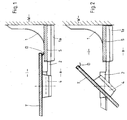
- one is preferably made Glass existing wall strip S by means of a bracket 1 on the wall W attached.
- This bracket 1 is perspective in the Fign. 3 to 5, once from inside to the other from the outside, shown.
- the illustration lacks a cover of the bracket 1.
- a support rail 2 is adjustable attached in the Fign. 4 and 5 shown in two different positions is. Also in these representations of the sake of clarity is a Outside cover of the bracket 1 omitted, which indicated in Fig. 1 and is provided with the reference numeral 1a.
- a fixed axle 3 On the mounting rail 2, a fixed axle 3 is arranged, the together with another support bolt in the area of the upper edge of the Wall strip S forms the pivot axis for a door T of the shower enclosure, of which a lying in the vicinity of the pivot axis part in Fig. 1 is shown.
- This door T is provided with a door fitting 4, which is on the outside of the door T is glued on.
- a door fitting 4 which is on the outside of the door T is glued on.
- the wall strip S nor the door T, usually made of Glass exist, are therefore provided with recesses or holes whose Incorporation in these glass components would be complicated and expensive.
- the fixed wall strip S covers a narrow strip of the closed door T, thus on the inside i the shower enclosure is located and a good seal against the outside a causes.
- the door T with a seal D be provided.
- bracket 1 has two slots 1b for wall mounting screws. At his vertical protruding from the wall W surface is the bracket 1 with a Receiving groove 1c provided for a retaining strip 1d, which the chamfered lower edge of the wall strip S accommodates. Means formed on the retaining strip 1d Guide pin 1e engages the retaining strip 1d in recesses 1f, which basically the receiving groove 1c are formed. In this way, the wall strip S reliably attached to the bracket 1.
- a Guide 1g formed for the horizontal adjustment of the support rail 2, the by two, a slot 2b by cross-fastening screws 2a in the desired position can be fastened.
- the head 5a of the adjusting screw 5 is by two am Bracket 1 formed forked bearing plates 1h set.
- Threaded shaft 5b of the adjusting screw 5 engages in a threaded bore 2c of the Support rail 2 a, so that depending on the direction of rotation of the adjusting screw 5 a Adjustment of the support rail 2 takes place.
- the bracket 1 By means of the wall mounting screws thus the distance of the through Bearing pin 3 predetermined pivot axis of the wall W can be adjusted.
- the outer cover 1a on the bracket 1 placed.
- Door fitting 4 has a bearing bore 4a for the bearing pin 3, which at her End 4b is hemispherical in shape.
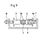
- a spring system cooperates, which in the Fign. 6 and 9 is shown. It consists of a pressure piece 6, which in storage areas 4c of the Door fitting is guided.
- the pressure piece 6 has a guide pin 6 a for a compression spring 7, which is supported with one end on the pressure piece 6.
- the other end of the compression spring 7 is supported on a bracket 8, which on the Pressure piece 6 opposite side of the axle 3 with a Balancing piece 9 is connected.
- the compound between bracket 8 and balance piece 9 by a screw 10 causes in a threaded bore 8 a of the bracket 8 is arranged and with its end on the Balance piece 9 acts. Also, the compensation piece 9 is in storage areas 4d of the Door fitting 4 slidably guided.
- the pressure piece 6 acts under the action of Compression spring 7 on one of the surfaces 3b of the axle 3 a. Since the Compression spring 7 is supported on the bracket 8, half of the spring force on the Adjusting screw 10 transferred to the balance piece 9, the axle 3 on loaded on the opposite surface 3b. The generated by the compression spring 7 Load is thus halved and on opposite sides of the axle 3 transferred.
- the force of the compression spring 7 can be adjusted continuously become. So it is possible, for example, under special conditions, the force completely cancel the compression spring 7, for example, during assembly work.
Landscapes
- Engineering & Computer Science (AREA)
- Mechanical Engineering (AREA)
- Health & Medical Sciences (AREA)
- Public Health (AREA)
- Epidemiology (AREA)
- General Health & Medical Sciences (AREA)
- Support Devices For Sliding Doors (AREA)
- Specific Sealing Or Ventilating Devices For Doors And Windows (AREA)
- Residential Or Office Buildings (AREA)
- Photoreceptors In Electrophotography (AREA)
- Control Of Throttle Valves Provided In The Intake System Or In The Exhaust System (AREA)
- Formation Of Various Coating Films On Cathode Ray Tubes And Lamps (AREA)
Abstract
Description
- Fig. 1
- einen waagerechten Schnitt durch die Duschabtrennung im Bereich des an der Wand befestigten Wandstreifens und eines Teiles der in der geschlossenen Stellung befindlichen Tür,
- Fig. 2
- einen weiteren Schnitt gemäß Fig. 1 bei um 45° geöffneter Tür,
- Fig. 3
- eine perspektivische Darstellung in Form eines Sprengbildes des den Wandstreifen aufnehmenden Haltewinkels,
- Fig. 4
- eine perspektivische Darstellung der am Haltewinkel verstellbar befestigten Tragschiene nahe der einen Endstellung und
- Fig. 5
- eine Darstellung gemäß Fig. 4 in der Nähe der anderen Endstellung der Tragschiene,
- Fig. 6
- ein Sprengbild des Türbeschlages,
- Fig. 7
- einen Querschnitt durch den Türbeschlag,
- Fig. 8
- einen Längsschnitt gemäß der Schnittlinie VIII-VIII in Fig. 7 durch den Türbeschlag und
- Fig. 9
- eine schematische Darstellung bezüglich der auf den Achsbolzen einwirkenden Kräfte.
- D
- Dichtung
- S
- Wandstreifen
- T
- Tür
- W
- Wand
- a
- Außenseite
- i
- Innenseite
- 1
- Haltewinkel
- 1a
- Abdeckung
- 1b
- Langloch
- 1c
- Aufnahmenut
- 1d
- Halteleiste
- 1e
- Führungsbolzen
- 1f
- Aussparung
- 1g
- Führung
- 1h
- Lagerlasche
- 2
- Tragschiene
- 2a
- Befestigungsschraube
- 2b
- Langloch
- 2c
- Gewindebohrung
- 3
- Achsbolzen
- 3a
- Kopf
- 3b
- Fläche
- 4
- Türbeschlag
- 4a
- Lagerbohrung
- 4b
- Ende
- 4c
- Lagerfläche
- 4d
- Lagerfläche
- 5
- Einstellschraube
- 5a
- Kopf
- 5b
- Gewindeschaft
- 6
- Druckstück
- 6a
- Führungsbolzen
- 7
- Druckfeder
- 8
- Bügel
- 8a
- Gewindebohrung
- 9
- Ausgleichstück
- 10
- Stellschraube
Claims (9)
- Duschabtrennung mit mindestens einer vorzugsweise aus Glas bestehenden Tür (T), die mittels zweier Beschläge an einem feststehenden, mittels zweier Haltewinkel (1) an der Wand (W) befestigten Wandstreifen (S), wiederum vorzugsweise aus Glas, um einen vorgegebenen Winkel verschwenkbar gelagert ist,
dadurch gekennzeichnet, daß an jedem Haltewinkel (1) eine Tragschiene (2) waagerecht einstellbar befestigt ist, die einen die Schwenkachse der Tür (T) bildenden Achsbolzen (3) trägt, der in eine Lagerbohrung (4a) in einem Türbeschlag (4) eingreift, der auf die Außenseite der Tür (T) aufgeklebt ist. - Duschabtrennung nach Anspruch 1, dadurch gekennzeichnet, daß der Kopf (3a) des Achsbolzens (3) als Halbkugel und das Ende (4b) der Lagerbohrung (4a) halbkugelförmig ausgebildet sind.
- Duschabtrennung nach Anspruch 1 und 2, dadurch gekennzeichnet, daß der Achsbolzen (3) mit abgeflachten Flächen (3b) versehen ist, mit denen ein durch eine Feder (7) belastetes Druckstück (6) zusammenwirkt.
- Duschabtrennung nach Anspruch 3, dadurch gekennzeichnet, daß die auf das Druckstück (6) einwirkende Feder (7) sich an ihrem anderen Ende an einem Bügel (8) abstützt, der mit einem auf die gegenüberliegende Seite des Achsbolzens (3) einwirkenden Ausgleichstück (9) versehen ist.
- Duschabtrennung nach Anspruch 4, dadurch gekennzeichnet, daß die Federkraft durch eine zwischen Bügel (8) und Ausgleichstück (9) angeordnete Stellschraube (10) einstellbar ist.
- Duschabtrennung nach mindestens einem der Ansprüche 1 bis 5, dadurch gekennzeichnet, daß die Tragschiene (2) mittels einer Führung (1g) am Haltewinkel (1) in waagerechter Richtung geführt und entlang dieser Führung (1g) durch eine Einstellschraube (5) verstellbar ist, deren Kopf (5a) zwischen zwei gabelförmigen Lagerlaschen (1a) des Haltewinkels (1) gelagert ist und deren Gewindeschaft (5b) in eine Gewindebohrung (2c) der Tragschiene (2) eingreift.
- Duschabtrennung nach Anspruch 6, dadurch gekennzeichnet, daß die Tragschiene (2) durch zwei in einem Langloch (2b) geführte Befestigungsschrauben (2a) am Haltewinkel (1) befestigbar ist.
- Duschabtrennung nach mindestens einem der Ansprüche 1 bis 7, dadurch gekennzeichnet, daß der Haltewinkel (1) mit einer Aufnahmenut (1c) für eine den oberen bzw. unteren Rand des Wandstreifens (S) aufnehmende Halteleiste (1d) versehen ist.
- Duschabtrennung nach Anspruch 8, dadurch gekennzeichnet, daß die Halteleiste (1d) mittels Führungsbolzen (1e) in Aussparungen (1f) des Haltewinkels (1) eingreift.
Priority Applications (1)
| Application Number | Priority Date | Filing Date | Title |
|---|---|---|---|
| PL04030538T PL1574651T3 (pl) | 2004-02-09 | 2004-12-23 | Przegroda prysznicowa |
Applications Claiming Priority (2)
| Application Number | Priority Date | Filing Date | Title |
|---|---|---|---|
| DE202004001967U | 2004-02-09 | ||
| DE202004001967U DE202004001967U1 (de) | 2004-02-09 | 2004-02-09 | Duschabtrennung |
Publications (3)
| Publication Number | Publication Date |
|---|---|
| EP1574651A2 true EP1574651A2 (de) | 2005-09-14 |
| EP1574651A3 EP1574651A3 (de) | 2009-10-07 |
| EP1574651B1 EP1574651B1 (de) | 2011-12-14 |
Family
ID=33103777
Family Applications (1)
| Application Number | Title | Priority Date | Filing Date |
|---|---|---|---|
| EP04030538A Expired - Lifetime EP1574651B1 (de) | 2004-02-09 | 2004-12-23 | Duschabtrennung |
Country Status (4)
| Country | Link |
|---|---|
| EP (1) | EP1574651B1 (de) |
| AT (1) | ATE537321T1 (de) |
| DE (1) | DE202004001967U1 (de) |
| PL (1) | PL1574651T3 (de) |
Families Citing this family (1)
| Publication number | Priority date | Publication date | Assignee | Title |
|---|---|---|---|---|
| FR3113081B1 (fr) * | 2020-07-29 | 2023-01-27 | Groupe Tirard & Burgaud Sas | Gond réglable |
Family Cites Families (7)
| Publication number | Priority date | Publication date | Assignee | Title |
|---|---|---|---|---|
| IT215091Z2 (it) * | 1988-12-16 | 1990-07-30 | Memo Spa | Cerniera con asse di articolazione orientabile |
| DE4119628C1 (en) * | 1991-06-14 | 1992-07-30 | Altura Leiden Holding B.V., Maastricht, Nl | Coupler for profiled rail and shower partition - has securing bracket in duct, adjacent laterally to clamping gap |
| DE9318246U1 (de) * | 1993-11-29 | 1994-10-27 | Società Italiana Progetti S.r.l., Magenta, Mailand/Milano | Tür- oder Fensterbeschlag |
| DE29619955U1 (de) * | 1996-11-16 | 1997-01-02 | Koralle Sanitärprodukte GmbH, 32602 Vlotho | Scharnier für eine Glastür |
| US6526627B2 (en) * | 2000-12-05 | 2003-03-04 | Fanny Chiang | Hinge auto-return device for a glass door |
| US6618871B2 (en) * | 2001-07-24 | 2003-09-16 | Kohler Co. | Shower door assembly |
| ITBS20010105A1 (it) * | 2001-12-13 | 2003-06-13 | Duka S R L | Porta per cabine doccia perfezionata |
-
2004
- 2004-02-09 DE DE202004001967U patent/DE202004001967U1/de not_active Expired - Lifetime
- 2004-12-23 EP EP04030538A patent/EP1574651B1/de not_active Expired - Lifetime
- 2004-12-23 PL PL04030538T patent/PL1574651T3/pl unknown
- 2004-12-23 AT AT04030538T patent/ATE537321T1/de active
Also Published As
| Publication number | Publication date |
|---|---|
| EP1574651B1 (de) | 2011-12-14 |
| PL1574651T3 (pl) | 2012-05-31 |
| ATE537321T1 (de) | 2011-12-15 |
| DE202004001967U1 (de) | 2004-09-30 |
| EP1574651A3 (de) | 2009-10-07 |
Similar Documents
| Publication | Publication Date | Title |
|---|---|---|
| DE4219681C2 (de) | Einstellbares Abhebescharnier | |
| DE602004002173T2 (de) | Einrichtung für eine höheneinstellbare Halterung eines Tores | |
| DE3738596C2 (de) | ||
| EP3103948B1 (de) | Band für eine tür oder ein fenster | |
| EP1331338B1 (de) | Band für Türen, Fenster und dergleichen | |
| EP2365167A2 (de) | Türband, insbesondere für Gebäudeabschlusstüren | |
| DE29602424U1 (de) | Tragteil für ein Verschlußelement, vorzugsweise für einen Türflügel einer Faltschiebetür | |
| DE9215565U1 (de) | Band für Türen, Fenster u.dgl. | |
| EP2754813B1 (de) | Band, insbesondere für Kunststoff-Türen und -Fenster | |
| EP3168398A1 (de) | Verstecktes scharnier für türen, fenster oder ähnliche bauteile | |
| EP1017920B1 (de) | Beschlag zur drehlagerung eines fenster- oder türflügels | |
| EP0478639A1 (de) | Scharnier. | |
| EP0318422B1 (de) | Einstellbares Gelenkband, insbesondere für Fenster und Türen | |
| EP3029227B2 (de) | Beschlag mit einstellbarem Einspannbereich | |
| DE60010806T2 (de) | Verdeckter Öffnungsbeschlag für Drehflügeltür oder -Fenster | |
| DE29817807U1 (de) | Dreidimensional verstellbares Aufschraubband für Tür- oder Fensterflügel | |
| EP0487825B1 (de) | Verdeckt angeordneter Beschlag für Drehflügel, insb. für Dreh-Kipp-Flügel von Fenstern oder Türen | |
| EP1574651B1 (de) | Duschabtrennung | |
| CH649341A5 (en) | Corner joint on a turn-and-tilt window or on a turn-and-tilt door | |
| EP1319786A1 (de) | Scharnier | |
| EP1223275B1 (de) | Band für Türen oder Fenster | |
| DE8111079U1 (de) | Ecklager fuer fluegel von fenstern, tueren od. dgl. | |
| DE2660245C2 (de) | Scharnier zum gelenkigen Verbinden zweier Bauteile | |
| EP1301676A1 (de) | Fenster oder tür mit entlastungseinrichtung | |
| EP1813751A1 (de) | Verdeckt liegendes Band |
Legal Events
| Date | Code | Title | Description |
|---|---|---|---|
| PUAI | Public reference made under article 153(3) epc to a published international application that has entered the european phase |
Free format text: ORIGINAL CODE: 0009012 |
|
| AK | Designated contracting states |
Kind code of ref document: A2 Designated state(s): AT BE BG CH CY CZ DE DK EE ES FI FR GB GR HU IE IS IT LI LT LU MC NL PL PT RO SE SI SK TR |
|
| AX | Request for extension of the european patent |
Extension state: AL BA HR LV MK YU |
|
| PUAL | Search report despatched |
Free format text: ORIGINAL CODE: 0009013 |
|
| AK | Designated contracting states |
Kind code of ref document: A3 Designated state(s): AT BE BG CH CY CZ DE DK EE ES FI FR GB GR HU IE IS IT LI LT LU MC NL PL PT RO SE SI SK TR |
|
| AX | Request for extension of the european patent |
Extension state: AL BA HR LV MK YU |
|
| 17P | Request for examination filed |
Effective date: 20091125 |
|
| AKX | Designation fees paid |
Designated state(s): AT BE BG CH CY CZ DE DK EE ES FI FR GB GR HU IE IS IT LI LT LU MC NL PL PT RO SE SI SK TR |
|
| 17Q | First examination report despatched |
Effective date: 20100607 |
|
| GRAP | Despatch of communication of intention to grant a patent |
Free format text: ORIGINAL CODE: EPIDOSNIGR1 |
|
| GRAS | Grant fee paid |
Free format text: ORIGINAL CODE: EPIDOSNIGR3 |
|
| GRAA | (expected) grant |
Free format text: ORIGINAL CODE: 0009210 |
|
| AK | Designated contracting states |
Kind code of ref document: B1 Designated state(s): AT BE BG CH CY CZ DE DK EE ES FI FR GB GR HU IE IS IT LI LT LU MC NL PL PT RO SE SI SK TR |
|
| REG | Reference to a national code |
Ref country code: GB Ref legal event code: FG4D Free format text: NOT ENGLISH |
|
| REG | Reference to a national code |
Ref country code: CH Ref legal event code: EP |
|
| REG | Reference to a national code |
Ref country code: CH Ref legal event code: NV Representative=s name: E. BLUM & CO. AG PATENT- UND MARKENANWAELTE VSP |
|
| REG | Reference to a national code |
Ref country code: DE Ref legal event code: R082 Ref document number: 502004013144 Country of ref document: DE Representative=s name: STENGER WATZKE RING INTELLECTUAL PROPERTY, DE |
|
| REG | Reference to a national code |
Ref country code: IE Ref legal event code: FG4D |
|
| PGFP | Annual fee paid to national office [announced via postgrant information from national office to epo] |
Ref country code: CH Payment date: 20111230 Year of fee payment: 8 Ref country code: FR Payment date: 20111221 Year of fee payment: 8 Ref country code: LU Payment date: 20111223 Year of fee payment: 8 Ref country code: NL Payment date: 20111228 Year of fee payment: 8 |
|
| REG | Reference to a national code |
Ref country code: NL Ref legal event code: T3 |
|
| REG | Reference to a national code |
Ref country code: DE Ref legal event code: R096 Ref document number: 502004013144 Country of ref document: DE Effective date: 20120301 |
|
| PG25 | Lapsed in a contracting state [announced via postgrant information from national office to epo] |
Ref country code: LT Free format text: LAPSE BECAUSE OF FAILURE TO SUBMIT A TRANSLATION OF THE DESCRIPTION OR TO PAY THE FEE WITHIN THE PRESCRIBED TIME-LIMIT Effective date: 20111214 |
|
| LTIE | Lt: invalidation of european patent or patent extension |
Effective date: 20111214 |
|
| PG25 | Lapsed in a contracting state [announced via postgrant information from national office to epo] |
Ref country code: GR Free format text: LAPSE BECAUSE OF FAILURE TO SUBMIT A TRANSLATION OF THE DESCRIPTION OR TO PAY THE FEE WITHIN THE PRESCRIBED TIME-LIMIT Effective date: 20120315 Ref country code: SI Free format text: LAPSE BECAUSE OF FAILURE TO SUBMIT A TRANSLATION OF THE DESCRIPTION OR TO PAY THE FEE WITHIN THE PRESCRIBED TIME-LIMIT Effective date: 20111214 Ref country code: SE Free format text: LAPSE BECAUSE OF FAILURE TO SUBMIT A TRANSLATION OF THE DESCRIPTION OR TO PAY THE FEE WITHIN THE PRESCRIBED TIME-LIMIT Effective date: 20111214 |
|
| PGFP | Annual fee paid to national office [announced via postgrant information from national office to epo] |
Ref country code: DE Payment date: 20111126 Year of fee payment: 8 |
|
| REG | Reference to a national code |
Ref country code: PL Ref legal event code: T3 |
|
| PG25 | Lapsed in a contracting state [announced via postgrant information from national office to epo] |
Ref country code: CY Free format text: LAPSE BECAUSE OF FAILURE TO SUBMIT A TRANSLATION OF THE DESCRIPTION OR TO PAY THE FEE WITHIN THE PRESCRIBED TIME-LIMIT Effective date: 20111214 |
|
| PGFP | Annual fee paid to national office [announced via postgrant information from national office to epo] |
Ref country code: GB Payment date: 20120104 Year of fee payment: 8 Ref country code: BE Payment date: 20120102 Year of fee payment: 8 |
|
| REG | Reference to a national code |
Ref country code: IE Ref legal event code: FD4D |
|
| PG25 | Lapsed in a contracting state [announced via postgrant information from national office to epo] |
Ref country code: EE Free format text: LAPSE BECAUSE OF FAILURE TO SUBMIT A TRANSLATION OF THE DESCRIPTION OR TO PAY THE FEE WITHIN THE PRESCRIBED TIME-LIMIT Effective date: 20111214 Ref country code: IE Free format text: LAPSE BECAUSE OF FAILURE TO SUBMIT A TRANSLATION OF THE DESCRIPTION OR TO PAY THE FEE WITHIN THE PRESCRIBED TIME-LIMIT Effective date: 20111214 Ref country code: IS Free format text: LAPSE BECAUSE OF FAILURE TO SUBMIT A TRANSLATION OF THE DESCRIPTION OR TO PAY THE FEE WITHIN THE PRESCRIBED TIME-LIMIT Effective date: 20120414 Ref country code: MC Free format text: LAPSE BECAUSE OF NON-PAYMENT OF DUE FEES Effective date: 20111231 Ref country code: BG Free format text: LAPSE BECAUSE OF FAILURE TO SUBMIT A TRANSLATION OF THE DESCRIPTION OR TO PAY THE FEE WITHIN THE PRESCRIBED TIME-LIMIT Effective date: 20120314 Ref country code: SK Free format text: LAPSE BECAUSE OF FAILURE TO SUBMIT A TRANSLATION OF THE DESCRIPTION OR TO PAY THE FEE WITHIN THE PRESCRIBED TIME-LIMIT Effective date: 20111214 Ref country code: CZ Free format text: LAPSE BECAUSE OF FAILURE TO SUBMIT A TRANSLATION OF THE DESCRIPTION OR TO PAY THE FEE WITHIN THE PRESCRIBED TIME-LIMIT Effective date: 20111214 |
|
| PG25 | Lapsed in a contracting state [announced via postgrant information from national office to epo] |
Ref country code: PT Free format text: LAPSE BECAUSE OF FAILURE TO SUBMIT A TRANSLATION OF THE DESCRIPTION OR TO PAY THE FEE WITHIN THE PRESCRIBED TIME-LIMIT Effective date: 20120416 Ref country code: RO Free format text: LAPSE BECAUSE OF FAILURE TO SUBMIT A TRANSLATION OF THE DESCRIPTION OR TO PAY THE FEE WITHIN THE PRESCRIBED TIME-LIMIT Effective date: 20111214 |
|
| PGFP | Annual fee paid to national office [announced via postgrant information from national office to epo] |
Ref country code: PL Payment date: 20111213 Year of fee payment: 8 |
|
| PGFP | Annual fee paid to national office [announced via postgrant information from national office to epo] |
Ref country code: IT Payment date: 20111216 Year of fee payment: 8 |
|
| PLBE | No opposition filed within time limit |
Free format text: ORIGINAL CODE: 0009261 |
|
| STAA | Information on the status of an ep patent application or granted ep patent |
Free format text: STATUS: NO OPPOSITION FILED WITHIN TIME LIMIT |
|
| PG25 | Lapsed in a contracting state [announced via postgrant information from national office to epo] |
Ref country code: DK Free format text: LAPSE BECAUSE OF FAILURE TO SUBMIT A TRANSLATION OF THE DESCRIPTION OR TO PAY THE FEE WITHIN THE PRESCRIBED TIME-LIMIT Effective date: 20111214 |
|
| 26N | No opposition filed |
Effective date: 20120917 |
|
| REG | Reference to a national code |
Ref country code: DE Ref legal event code: R097 Ref document number: 502004013144 Country of ref document: DE Effective date: 20120917 |
|
| PG25 | Lapsed in a contracting state [announced via postgrant information from national office to epo] |
Ref country code: ES Free format text: LAPSE BECAUSE OF FAILURE TO SUBMIT A TRANSLATION OF THE DESCRIPTION OR TO PAY THE FEE WITHIN THE PRESCRIBED TIME-LIMIT Effective date: 20120325 |
|
| PG25 | Lapsed in a contracting state [announced via postgrant information from national office to epo] |
Ref country code: FI Free format text: LAPSE BECAUSE OF FAILURE TO SUBMIT A TRANSLATION OF THE DESCRIPTION OR TO PAY THE FEE WITHIN THE PRESCRIBED TIME-LIMIT Effective date: 20111214 |
|
| BERE | Be: lapsed |
Owner name: KORALLE SANITARPRODUKTE G.M.B.H. Effective date: 20121231 |
|
| REG | Reference to a national code |
Ref country code: NL Ref legal event code: V1 Effective date: 20130701 |
|
| REG | Reference to a national code |
Ref country code: CH Ref legal event code: PL |
|
| REG | Reference to a national code |
Ref country code: AT Ref legal event code: MM01 Ref document number: 537321 Country of ref document: AT Kind code of ref document: T Effective date: 20121223 |
|
| GBPC | Gb: european patent ceased through non-payment of renewal fee |
Effective date: 20121223 |
|
| REG | Reference to a national code |
Ref country code: FR Ref legal event code: ST Effective date: 20130830 |
|
| PG25 | Lapsed in a contracting state [announced via postgrant information from national office to epo] |
Ref country code: BE Free format text: LAPSE BECAUSE OF NON-PAYMENT OF DUE FEES Effective date: 20121231 Ref country code: TR Free format text: LAPSE BECAUSE OF FAILURE TO SUBMIT A TRANSLATION OF THE DESCRIPTION OR TO PAY THE FEE WITHIN THE PRESCRIBED TIME-LIMIT Effective date: 20111214 |
|
| REG | Reference to a national code |
Ref country code: DE Ref legal event code: R119 Ref document number: 502004013144 Country of ref document: DE Effective date: 20130702 |
|
| PG25 | Lapsed in a contracting state [announced via postgrant information from national office to epo] |
Ref country code: NL Free format text: LAPSE BECAUSE OF NON-PAYMENT OF DUE FEES Effective date: 20130701 Ref country code: AT Free format text: LAPSE BECAUSE OF NON-PAYMENT OF DUE FEES Effective date: 20121223 Ref country code: DE Free format text: LAPSE BECAUSE OF NON-PAYMENT OF DUE FEES Effective date: 20130702 Ref country code: CH Free format text: LAPSE BECAUSE OF NON-PAYMENT OF DUE FEES Effective date: 20121231 Ref country code: HU Free format text: LAPSE BECAUSE OF FAILURE TO SUBMIT A TRANSLATION OF THE DESCRIPTION OR TO PAY THE FEE WITHIN THE PRESCRIBED TIME-LIMIT Effective date: 20111214 Ref country code: LI Free format text: LAPSE BECAUSE OF NON-PAYMENT OF DUE FEES Effective date: 20121231 |
|
| PG25 | Lapsed in a contracting state [announced via postgrant information from national office to epo] |
Ref country code: FR Free format text: LAPSE BECAUSE OF NON-PAYMENT OF DUE FEES Effective date: 20130102 Ref country code: GB Free format text: LAPSE BECAUSE OF NON-PAYMENT OF DUE FEES Effective date: 20121223 |
|
| PG25 | Lapsed in a contracting state [announced via postgrant information from national office to epo] |
Ref country code: IT Free format text: LAPSE BECAUSE OF NON-PAYMENT OF DUE FEES Effective date: 20121223 |
|
| PG25 | Lapsed in a contracting state [announced via postgrant information from national office to epo] |
Ref country code: PL Free format text: LAPSE BECAUSE OF NON-PAYMENT OF DUE FEES Effective date: 20121223 |
|
| PG25 | Lapsed in a contracting state [announced via postgrant information from national office to epo] |
Ref country code: LU Free format text: LAPSE BECAUSE OF NON-PAYMENT OF DUE FEES Effective date: 20121223 |