EP1574424B1 - Motor vehicle dismantling line - Google Patents
Motor vehicle dismantling line Download PDFInfo
- Publication number
- EP1574424B1 EP1574424B1 EP20050003488 EP05003488A EP1574424B1 EP 1574424 B1 EP1574424 B1 EP 1574424B1 EP 20050003488 EP20050003488 EP 20050003488 EP 05003488 A EP05003488 A EP 05003488A EP 1574424 B1 EP1574424 B1 EP 1574424B1
- Authority
- EP
- European Patent Office
- Prior art keywords
- vehicle
- dismantling
- motor vehicle
- line
- workstations
- Prior art date
- Legal status (The legal status is an assumption and is not a legal conclusion. Google has not performed a legal analysis and makes no representation as to the accuracy of the status listed.)
- Expired - Lifetime
Links
- 230000007306 turnover Effects 0.000 claims description 32
- 238000000034 method Methods 0.000 claims description 19
- 230000008569 process Effects 0.000 claims description 13
- 230000005540 biological transmission Effects 0.000 claims description 10
- 210000000078 claw Anatomy 0.000 claims description 6
- 238000000151 deposition Methods 0.000 claims description 3
- 230000000630 rising effect Effects 0.000 claims description 3
- 230000032258 transport Effects 0.000 claims description 3
- 230000009471 action Effects 0.000 claims description 2
- 230000008901 benefit Effects 0.000 description 6
- 230000003197 catalytic effect Effects 0.000 description 3
- 238000005520 cutting process Methods 0.000 description 3
- 230000015556 catabolic process Effects 0.000 description 2
- 230000001965 increasing effect Effects 0.000 description 2
- 238000004064 recycling Methods 0.000 description 2
- 239000006096 absorbing agent Substances 0.000 description 1
- 230000000694 effects Effects 0.000 description 1
- 230000003028 elevating effect Effects 0.000 description 1
- 239000005357 flat glass Substances 0.000 description 1
- 239000012634 fragment Substances 0.000 description 1
- 238000010438 heat treatment Methods 0.000 description 1
- 230000003116 impacting effect Effects 0.000 description 1
- 238000012423 maintenance Methods 0.000 description 1
- 238000004519 manufacturing process Methods 0.000 description 1
- 239000000463 material Substances 0.000 description 1
- 239000002994 raw material Substances 0.000 description 1
- 230000035939 shock Effects 0.000 description 1
- 230000001360 synchronised effect Effects 0.000 description 1
- 239000002699 waste material Substances 0.000 description 1
- XLYOFNOQVPJJNP-UHFFFAOYSA-N water Substances O XLYOFNOQVPJJNP-UHFFFAOYSA-N 0.000 description 1
Images


Classifications
-
- B—PERFORMING OPERATIONS; TRANSPORTING
- B62—LAND VEHICLES FOR TRAVELLING OTHERWISE THAN ON RAILS
- B62D—MOTOR VEHICLES; TRAILERS
- B62D67/00—Systematic disassembly of vehicles for recovery of salvageable components, e.g. for recycling
-
- Y—GENERAL TAGGING OF NEW TECHNOLOGICAL DEVELOPMENTS; GENERAL TAGGING OF CROSS-SECTIONAL TECHNOLOGIES SPANNING OVER SEVERAL SECTIONS OF THE IPC; TECHNICAL SUBJECTS COVERED BY FORMER USPC CROSS-REFERENCE ART COLLECTIONS [XRACs] AND DIGESTS
- Y02—TECHNOLOGIES OR APPLICATIONS FOR MITIGATION OR ADAPTATION AGAINST CLIMATE CHANGE
- Y02W—CLIMATE CHANGE MITIGATION TECHNOLOGIES RELATED TO WASTEWATER TREATMENT OR WASTE MANAGEMENT
- Y02W30/00—Technologies for solid waste management
- Y02W30/50—Reuse, recycling or recovery technologies
- Y02W30/56—Reuse, recycling or recovery technologies of vehicles
Definitions
- the present description relates, as its title indicates, to a motor vehicle dismantling line, of the type used industrially to recycle motor vehicles taken off the road to allow parts and components to be reused, characterised in that the process is conducted by moving the motor vehicle between the various handling points directly on conveyor chains, and in that it uses one or more external turnover units to lift the motor vehicle from the conveyor line, rotate it and move it to a workstation, also external, where operations to dismantle the bottom part and the engine are conducted, with these turnover units then returning the remnants of the vehicle to the conveyor chains in order to continue with the dismantling process.
- Patent JP2003170871 “Method of scrapping car” in which the vehicle is opened by means of a lower longitudinal cut made by a saw with elements then being removed by a robotic arm fitted with a saw or welder that automatically selects each part to be recovered; or that protected by Patent JP2003212164 , “Method and device for scrapping used cars”, in which in a relatively similar way cuts are made by a saw operated by a robotic arm or gantry crane to divide the vehicle into commercially useful and less useful parts before being moved onto different processing lines.
- Patent JP2003212164 “Method and device for scrapping used cars” in which in a relatively similar way cuts are made by a saw operated by a robotic arm or gantry crane to divide the vehicle into commercially useful and less useful parts before being moved onto different processing lines.
- the disadvantage of these systems is that they require highly complex and specialised facilities, involving high costs, and furthermore do not enable optimal use of the majority of the vehicle's recyclable parts.
- Patent DE4143251 "Verfahren und Vorcardi Kunststoff PKW-Demontage” which consist of a double cutting machine with 90° rotation allowing bodywork to be cut into various fragments, which also has the problem of not enabling optimal use of the majority of the vehicle's recyclable parts.
- the system claimed in Patent DE19609572 "Car dismantling via connections into single parts”, conducts a similar process but by means of pressurised water jet cutting to separate the connections connecting the various elements, with the cutting process being assisted by a manipulator that positions the vehicle at a suitable angle of rotation beforehand, but which presents the same problems as those detailed above.
- systems such as that disclosed in European Patent 92202671 , "Method and device for dismantling automobiles", and European Patent 95200931 , “Device for scrapping cars”, are also widely known and used industrially and are based on dismantling lines in which the vehicles are transported on special platforms, onto which they must be deposited by a special crane or similar device, incorporating as an integral part of the dismantling line run, special cranes to lift up the vehicle so that the bottom part of it can be dismantled, or special rotating devices forming an integral part of the line in order to rotate the vehicle so that the bottom part of it can be removed, which must then be raised by another special crane so that it can be removed from the vehicle.
- DE 4333632 A1 shows a motor vehicle dismantling line, the type used industrially to recycle motor vehicles taken off the road to allow parts and components to be reused.
- This dismantling line is using parallel conveyer chains for transporting the cars to be dismantled.
- the conveyer chains are arranged on the ground level of the facility.
- the conveyer chains are arranged above pits. This way, no turn over units are needed. Only a full gantry crane is provided to lift the cars vertically if needed.
- the dismantling of parts underneath the car, e.g. the catalytic converter, is entirely executed on the lower work level, i.e. in the pit.
- FR 2760389 A1 discloses a vertical lifting and turn over unit. This turn over unit is rotateably arranged on a vertical pole. This way, several work stations can be arranged in a circle to entirely dismantle the car. According to the disclosure of FR 2760389 A1 , the rotateabel turn over units have been chosen to explicitly avoid transportation of the cars on conveyer lines.
- the motor vehicle dismantling line that is the object of this invention has been designed and consists of an operating line comprising a preferably metallic fixed structure, considerably longer than it is wide, and which comprises two parallel conveyor chains running longitudinally and fitted with the appropriate motor or motors and the corresponding planetary gears, automatically transporting the vehicles all the way along the line.
- an operating line comprising a preferably metallic fixed structure, considerably longer than it is wide, and which comprises two parallel conveyor chains running longitudinally and fitted with the appropriate motor or motors and the corresponding planetary gears, automatically transporting the vehicles all the way along the line.
- On either side of the conveyor structure several regularly spaced specialised dismantling stations are located and possess the requisite tools, containers and personnel to dismantle one or more specific elements of the vehicle.
- the vehicle to be dismantled is positioned at the front of the line in the positioning area, being deposited by a fork-lift truck directly onto some load supports, which are synchronised with the movement of the conveyor chain and by means of a simple device they descend to allow the bottom part of the vehicle bodywork to rest directly on the top part of the conveyor chain links, which move to transport the vehicle all the way along the dismantling line.
- the conveyor chains are positioned at the requisite distance depending on the vehicles to be dismantled.
- the unit itself rotates upon the longitudinal axis of the vehicle in such a way that the vehicle is rotated 90°/180° (depending on the method) at approximately the point at which it reaches the external dismantling workstation, being held in a fixed position so that the personnel manning these stations can carry out operations on the bottom part, such as releasing the attachment points of the engine, the gearbox and the transmission, and dismantling the exhaust pipe, catalytic converter etc.
- the turnover unit is equipped to rotate the vehicle upon its longitudinal axis at any angle, keeping it in this position to allow easy access for personnel and to adapt to any type of particular dismantling needs concerning the vehicles that may appear.
- Every turnover unit in the same workstation or in another, depending on the operation, rotates the vehicle on its longitudinal axis again until it returns to its original angle positioned above a collector tray onto which, following operations to detach these elements from the bodywork, the engine, gearbox and transmission, etc. are deposited before being transported on said collector tray by a fork lift tray to an additional auxiliary dismantling position or to their final destination.
- the turnover unit continues to rotate in order to move the vehicle, which now consists of bodywork with few remaining elements, until it deposits it once more on the conveyor chains in the line, in a position more advanced than the one it occupied previously, so that the process of conveying it through the remaining dismantling workstations can continue.
- the turnover unit is constructed in the form of a tower, provided with rotating movement in relation to its vertical axis, and equipped on one side with a lifting device that causes the independent vertical rising and descending movement of a side arm.
- this side arm is provided with rotating movement in relation to a horizontal axis situated at the point of connection with the lifting device.
- On the other end of the arm there is a fastening claw for the vehicle, connected to the arm through another additional axis of rotation.
- This claw consists of two arms, the ends of which are equipped with wedges that hold the vehicle firmly from the sides and the bottom part without any risk of it falling while being turned over, and which are operated by conventional-type hydraulic, pneumatic or electrical devices.
- one or more turnover units can be installed adjacent to the conveyor chain with their corresponding external dismantling workstations.
- the number of dismantling phases and associated workstations can also be varied without difficulty, adapting it easily to every specific type of facility.
- a vehicle removal area consisting of load supports similar to those located at the front of the line and which lift up the final remnants of the vehicle, usually the bodywork itself, from the links on the conveyor chains so that they can be collected by a fork lift truck and deposited in their final destination.
- the dismantling phases can be divided in various ways in accordance with the particular specifications and specific needs of each particular dismantling line set-up.
- a preferred example of the various dismantling phases is:
- the motor vehicle dismantling line presented herein provides numerous advantages over the systems currently available, the most important of which is that since the vehicles are transported directly on the conveyor chain, complex conveyor platforms, which make the line more expensive and complex, are not required, thus resulting in a mechanically simpler and therefore more inexpensive dismantling line.
- elevating load supports at the front and rear of the line enable the vehicle to be carried and the bodywork removed with a fork lift truck only, doing away with the need for expensive lifting or gantry cranes.
- Another advantage of the present invention is that the turnover units enable the vehicle-holding, lifting, transfer and rotation movements to be conducted simultaneously in a coordinated way.
- the turnover unit is used to dismantle the vehicle, remove the engine, gearbox and transmission, and return the bodywork to the line without the need for cranes, thus simplifying the whole process greatly and optimising removal time.
- the versatility of the turnover unit means that it can perform either 90° turnovers if removal is to be conducted at a single workstation, or 180° turnovers if removal is to be conducted at multiple workstations, and it is also capable of adapting to any intermediate angle of rotation that may be needed to dismantle any vehicle or perform any operation in particular.
- Another added advantage is that as the most dangerous tasks are performed in an area separated from the conveyor line, and since the motor vehicle is held firmly by the turnover unit, the risk of personnel suffering accidents is greatly reduced, thereby improving overall safety at the facility.
- plan attached details a preferred practical embodiment of an example of a motor vehicle dismantling line.
- Figure 2 shows a ground view of the line.
- Figure 3 shows a side view of the line, divided into two to increase the scale of the drawing and make it easier to understand.
- Figure 4 shows a front and profile view of a turnover unit holding and lifting a vehicle.
- Figure 5 shows a view of an external dismantling workstation for work on the bottom part, with a motor vehicle rotated 180°.
- Figure 6 shows a standard external dismantling workstation with a motor vehicle rotated at 90° and in different positions to facilitate operations at a single workstation.
- Figure 7 is a sectional view of the operating sequence of the load supports in the positioning area at the front of the line.
- Figure 8 is a sectional view of the position of the vehicle above the conveyor chains.
- Figure 9 shows a close up of the sequence wherein the claw on the turnover unit attaches itself onto the vehicle and lifts it onto the conveyor line, and then returns it.
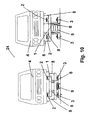
- Figure 10 shows a sectional view of the operating sequence of the load supports in the vehicle removal area at the rear of the line.
- the motor vehicle dismantling line that is the object of the present invention, is essentially formed, as can be seen in the drawing attached, by a preferably metallic fixed structure (1), considerably longer than it is wide, and which comprises two parallel conveyor chains (2) running longitudinally and fitted with the appropriate motor or motors and the corresponding planetary gears (3), automatically transporting the vehicles (4) all the way along the line.
- a preferably metallic fixed structure (1) which comprises two parallel conveyor chains (2) running longitudinally and fitted with the appropriate motor or motors and the corresponding planetary gears (3), automatically transporting the vehicles (4) all the way along the line.
- On either side of the structure (1) several regularly spaced, specialised dismantling workstations (5) are located.
- the vehicle (4) to be dismantled is positioned at the front of the line in the positioning area (6) being deposited by a fork lift truck (7) directly onto some load supports (8) which, in their raised position receive the vehicle from the fork lift truck, and by means of a simple device (9) deposit the vehicle (4) directly onto the conveyor chains (2).
- Each turnover unit is constructed in the form of a tower (12), provided with rotating movement in relation to its vertical axis (13) and equipped with a lifting device that causes the independent vertical rising and descending movement of a side arm (15).
- this side arm (15) is provided with rotating movement in relation to a horizontal axis (16) situated at the point of connection with the lifting device.
- This fastening claw (17) On the other end of the side arm (15) there is a fastening claw (17) for the vehicle, connected to the side arm (15) through another additional axis of rotation (18).
- This fastening claw (17) consists of two clamping arms (19) the ends of which are equipped with wedges (20) that hold the vehicle (4) firmly from the sides and the bottom part without any risk of it falling while being turned over, and which are operated by conventional-type hydraulic, pneumatic or electrical devices.
- each turnover unit lifts the vehicle up again and transports it to an unloading area situated within its radius of action, where it rotates the vehicle on its longitudinal axis again until it returns to its original angle positioned above a collector tray (14) onto which the engine, gearbox and transmission, etc. are deposited before being transported on said collector tray (14) by a fork lift truck (7) to an additional auxiliary dismantling workstation or to their final destination.
- the turnover unit (10) continues to rotate, moving the vehicle (4) until depositing it once more on the conveyor chains in the line, in a position (22) more advanced than the one it occupied previously (23) so that the process of conveying it through the remaining dismantling workstations can continue.
- a vehicle removal area (24) consisting of load supports similar to those located at the front of the line.
Landscapes
- Engineering & Computer Science (AREA)
- Life Sciences & Earth Sciences (AREA)
- Sustainable Development (AREA)
- Chemical & Material Sciences (AREA)
- Combustion & Propulsion (AREA)
- Transportation (AREA)
- Mechanical Engineering (AREA)
- Automobile Manufacture Line, Endless Track Vehicle, Trailer (AREA)
- Processing Of Solid Wastes (AREA)
- Forklifts And Lifting Vehicles (AREA)
Abstract
Description
- The present description relates, as its title indicates, to a motor vehicle dismantling line, of the type used industrially to recycle motor vehicles taken off the road to allow parts and components to be reused, characterised in that the process is conducted by moving the motor vehicle between the various handling points directly on conveyor chains, and in that it uses one or more external turnover units to lift the motor vehicle from the conveyor line, rotate it and move it to a workstation, also external, where operations to dismantle the bottom part and the engine are conducted, with these turnover units then returning the remnants of the vehicle to the conveyor chains in order to continue with the dismantling process.
- Current regulations in various countries, allied to increased concern regarding waste originating from motor vehicles has now created a need to dismantle, decontaminate and attempt to recycle as many parts as possible belonging to motor vehicles taken off the road for whatever reason. Traditionally motor vehicles have been dismantled by hand, an activity largely linked to demand for usable parts.
- However, new systems and devices that attempt to conduct this dismantling process in the most industrial and productive way possible have begun to appear. Consequently, arrangements have become known such as that disclosed in
European Patent 93200702 - Other systems are also known such as that protected by
European Patent 91109649 - There are also systems such as that claimed in
Patent JP2003170871 Patent JP2003212164 - Systems are also used such as that protected by
Patent DE4143251 , "Verfahren und Vorrichtung zur PKW-Demontage", which consist of a double cutting machine with 90° rotation allowing bodywork to be cut into various fragments, which also has the problem of not enabling optimal use of the majority of the vehicle's recyclable parts. The system claimed inPatent DE19609572 , "Car dismantling via connections into single parts", conducts a similar process but by means of pressurised water jet cutting to separate the connections connecting the various elements, with the cutting process being assisted by a manipulator that positions the vehicle at a suitable angle of rotation beforehand, but which presents the same problems as those detailed above. - There are also systems on the market such as that protected by
European Patent 93200702 - Further, systems such as that disclosed in
European Patent 92202671 European Patent 95200931 -
DE 4333632 A1 shows a motor vehicle dismantling line, the type used industrially to recycle motor vehicles taken off the road to allow parts and components to be reused. This dismantling line is using parallel conveyer chains for transporting the cars to be dismantled. The conveyer chains are arranged on the ground level of the facility. The conveyer chains are arranged above pits. This way, no turn over units are needed. Only a full gantry crane is provided to lift the cars vertically if needed. The dismantling of parts underneath the car, e.g. the catalytic converter, is entirely executed on the lower work level, i.e. in the pit. -
FR 2760389 A1 FR 2760389 A1 - To address current problems in the dismantling and recycling of motor vehicles, the motor vehicle dismantling line that is the object of this invention has been designed and consists of an operating line comprising a preferably metallic fixed structure, considerably longer than it is wide, and which comprises two parallel conveyor chains running longitudinally and fitted with the appropriate motor or motors and the corresponding planetary gears, automatically transporting the vehicles all the way along the line. On either side of the conveyor structure several regularly spaced specialised dismantling stations are located and possess the requisite tools, containers and personnel to dismantle one or more specific elements of the vehicle.
- The vehicle to be dismantled is positioned at the front of the line in the positioning area, being deposited by a fork-lift truck directly onto some load supports, which are synchronised with the movement of the conveyor chain and by means of a simple device they descend to allow the bottom part of the vehicle bodywork to rest directly on the top part of the conveyor chain links, which move to transport the vehicle all the way along the dismantling line. The conveyor chains are positioned at the requisite distance depending on the vehicles to be dismantled.
- In this way the conveyor chains automatically move the vehicle, which thus passes through the various dismantling workstations where the operators remove, in different phases, the various elements of the vehicle.
- Towards the start of the second half of the line, to the sides and at a certain distance from it, can be found separate turnover units whose function it is to take a vehicle from the conveyor line, hold it, lift it up and, by means of a rotating movement, transfer it to dismantling workstations that are external to the conveyor line and which specialise in working on the bottom part of the vehicle. At the same time as this movement occurs, the unit itself rotates upon the longitudinal axis of the vehicle in such a way that the vehicle is rotated 90°/180° (depending on the method) at approximately the point at which it reaches the external dismantling workstation, being held in a fixed position so that the personnel manning these stations can carry out operations on the bottom part, such as releasing the attachment points of the engine, the gearbox and the transmission, and dismantling the exhaust pipe, catalytic converter etc. The turnover unit is equipped to rotate the vehicle upon its longitudinal axis at any angle, keeping it in this position to allow easy access for personnel and to adapt to any type of particular dismantling needs concerning the vehicles that may appear.
- Once the personnel have released the lower attachment points of the engine, gearbox and transmission, etc. every turnover unit, in the same workstation or in another, depending on the operation, rotates the vehicle on its longitudinal axis again until it returns to its original angle positioned above a collector tray onto which, following operations to detach these elements from the bodywork, the engine, gearbox and transmission, etc. are deposited before being transported on said collector tray by a fork lift tray to an additional auxiliary dismantling position or to their final destination.
- The turnover unit continues to rotate in order to move the vehicle, which now consists of bodywork with few remaining elements, until it deposits it once more on the conveyor chains in the line, in a position more advanced than the one it occupied previously, so that the process of conveying it through the remaining dismantling workstations can continue.
- To achieve this, the turnover unit is constructed in the form of a tower, provided with rotating movement in relation to its vertical axis, and equipped on one side with a lifting device that causes the independent vertical rising and descending movement of a side arm. In addition, this side arm is provided with rotating movement in relation to a horizontal axis situated at the point of connection with the lifting device. On the other end of the arm there is a fastening claw for the vehicle, connected to the arm through another additional axis of rotation. This claw consists of two arms, the ends of which are equipped with wedges that hold the vehicle firmly from the sides and the bottom part without any risk of it falling while being turned over, and which are operated by conventional-type hydraulic, pneumatic or electrical devices.
- Depending on the required production rate of the dismantling line one or more turnover units can be installed adjacent to the conveyor chain with their corresponding external dismantling workstations. The number of dismantling phases and associated workstations can also be varied without difficulty, adapting it easily to every specific type of facility.
- At the rear of the line there is a vehicle removal area consisting of load supports similar to those located at the front of the line and which lift up the final remnants of the vehicle, usually the bodywork itself, from the links on the conveyor chains so that they can be collected by a fork lift truck and deposited in their final destination.
- The dismantling phases can be divided in various ways in accordance with the particular specifications and specific needs of each particular dismantling line set-up. A preferred example of the various dismantling phases is:
- PHASE 1 - Removal of window glass, doors, front bonnet, rear bonnet, external lights, and rubber from the window frames.
- PHASE 2 - Removal of seats, upholstery and bumpers.
- PHASE 3 - Removal of airbag, inertia-reel seatbelts and dashboard.
- PHASE 4 - Releasing of lower attachment points, engine, gearbox and transmission. Dismantling of exhaust pipe and catalytic converter.
- PHASE 5 - Releasing of upper attachment points, shock absorbers, and removal of engine and transmission.
- PHASE 6 - Removal of rest of parts, cables, heating, radiators and tanks.
- The motor vehicle dismantling line presented herein provides numerous advantages over the systems currently available, the most important of which is that since the vehicles are transported directly on the conveyor chain, complex conveyor platforms, which make the line more expensive and complex, are not required, thus resulting in a mechanically simpler and therefore more inexpensive dismantling line.
- Another important advantage is that the elevating load supports at the front and rear of the line enable the vehicle to be carried and the bodywork removed with a fork lift truck only, doing away with the need for expensive lifting or gantry cranes.
- Another advantage of the present invention is that the turnover units enable the vehicle-holding, lifting, transfer and rotation movements to be conducted simultaneously in a coordinated way.
- Another of the most noteworthy advantages is that the turnover unit is used to dismantle the vehicle, remove the engine, gearbox and transmission, and return the bodywork to the line without the need for cranes, thus simplifying the whole process greatly and optimising removal time.
- It should be pointed out that the versatility of the turnover unit means that it can perform either 90° turnovers if removal is to be conducted at a single workstation, or 180° turnovers if removal is to be conducted at multiple workstations, and it is also capable of adapting to any intermediate angle of rotation that may be needed to dismantle any vehicle or perform any operation in particular.
- In addition another added advantage is that as the most dangerous tasks are performed in an area separated from the conveyor line, and since the motor vehicle is held firmly by the turnover unit, the risk of personnel suffering accidents is greatly reduced, thereby improving overall safety at the facility.
- Finally, we should mention the significant advantage represented by having the turnover units located externally to the conveyor chain, since this allows more than one turnover unit to be installed, thus reducing process times, increasing the speed of the dismantling line and eliminating downtime, making it easily adaptable to the specific needs of each dismantling plant.
- Finally, it should be remembered that all these improvements and mechanical simplifications result in a more economical, more productive dismantling line with less breakdowns and maintenance work.
- To provide a better understanding of the present invention, the plan attached details a preferred practical embodiment of an example of a motor vehicle dismantling line.
- In said plan
figure 1 shows a generic view in perspective of the whole line. -
Figure 2 shows a ground view of the line. -
Figure 3 shows a side view of the line, divided into two to increase the scale of the drawing and make it easier to understand. -
Figure 4 shows a front and profile view of a turnover unit holding and lifting a vehicle. -
Figure 5 shows a view of an external dismantling workstation for work on the bottom part, with a motor vehicle rotated 180°. -
Figure 6 shows a standard external dismantling workstation with a motor vehicle rotated at 90° and in different positions to facilitate operations at a single workstation. -
Figure 7 is a sectional view of the operating sequence of the load supports in the positioning area at the front of the line. -
Figure 8 is a sectional view of the position of the vehicle above the conveyor chains. -
Figure 9 shows a close up of the sequence wherein the claw on the turnover unit attaches itself onto the vehicle and lifts it onto the conveyor line, and then returns it. -
Figure 10 shows a sectional view of the operating sequence of the load supports in the vehicle removal area at the rear of the line. - The motor vehicle dismantling line that is the object of the present invention, is essentially formed, as can be seen in the drawing attached, by a preferably metallic fixed structure (1), considerably longer than it is wide, and which comprises two parallel conveyor chains (2) running longitudinally and fitted with the appropriate motor or motors and the corresponding planetary gears (3), automatically transporting the vehicles (4) all the way along the line. On either side of the structure (1) several regularly spaced, specialised dismantling workstations (5) are located.
- The vehicle (4) to be dismantled is positioned at the front of the line in the positioning area (6) being deposited by a fork lift truck (7) directly onto some load supports (8) which, in their raised position receive the vehicle from the fork lift truck, and by means of a simple device (9) deposit the vehicle (4) directly onto the conveyor chains (2).
- Towards the start of the second half of the line, to the sides and at a certain distance from it, can be found separate turnover units (10) whose function it is to take a vehicle (4) from the conveyor line, hold it, lift it up and, by means of a rotating movement transfer it to the external dismantling workstations (11). Each turnover unit is constructed in the form of a tower (12), provided with rotating movement in relation to its vertical axis (13) and equipped with a lifting device that causes the independent vertical rising and descending movement of a side arm (15). In addition this side arm (15) is provided with rotating movement in relation to a horizontal axis (16) situated at the point of connection with the lifting device. On the other end of the side arm (15) there is a fastening claw (17) for the vehicle, connected to the side arm (15) through another additional axis of rotation (18). This fastening claw (17) consists of two clamping arms (19) the ends of which are equipped with wedges (20) that hold the vehicle (4) firmly from the sides and the bottom part without any risk of it falling while being turned over, and which are operated by conventional-type hydraulic, pneumatic or electrical devices.
- Once the personnel have released the attachment points of the engine, gearbox and transmission, etc. each turnover unit lifts the vehicle up again and transports it to an unloading area situated within its radius of action, where it rotates the vehicle on its longitudinal axis again until it returns to its original angle positioned above a collector tray (14) onto which the engine, gearbox and transmission, etc. are deposited before being transported on said collector tray (14) by a fork lift truck (7) to an additional auxiliary dismantling workstation or to their final destination. The turnover unit (10) continues to rotate, moving the vehicle (4) until depositing it once more on the conveyor chains in the line, in a position (22) more advanced than the one it occupied previously (23) so that the process of conveying it through the remaining dismantling workstations can continue.
- At the rear of the line is situated a vehicle removal area (24) consisting of load supports similar to those located at the front of the line.
- It was decided to omit a detailed description of the other particular features of the system being disclosed or of the components forming part of it, as it was felt that the rest of said particular features are not the object of any claims.
- Having described the nature of the present invention in sufficient detail, in addition to the means of putting it into practice, all that remains to be added is that its description is not restrictive, and that variations both in materials and shapes and sizes can be made provided that said variations do not alter the essential nature of the characteristics claimed below.
Claims (8)
- Motor vehicle dismantling line, of the type used industrially to recycle motor vehicles taken off the road to allow parts and components to be reused, consisting of a metallic fixed structure (1), extending longer than wide, and comprising two parallel conveyor chains (2) running longitudinally and fitted with the appropriate motor or motors and the corresponding planetary gears (3), automatically transporting the vehicles (4) all the way along the line, and with various dismantling workstations (5) being located on either side of the structure (1),
characterised in that
it comprises one or more separate turnover units (10) situated at around the start of the second half of the structure (1), to the sides and at a certain distance from it, constructed in the form of a tower (12), provided with rotating movement in relation to its vertical axis (13) and equipped with a lifting device that causes the independent vertical rising and descending movement of a side arm (15), and which is provided with rotating movement in relation to a horizontal axis (16) situated at the point of connection with the lifting device. - Motor vehicle dismantling line according to the preceding claim, wherein it comprises at the front of the structure (1) load supports consisting of rails (8) which when raised receive the vehicle from a fork lift truck (7), before descending in synchronisation with the conveyor chain by means of a device (9), depositing the vehicle (4) directly on the conveyor chains (2).
- Motor vehicle dismantling line according to the preceding claims, wherein it comprises at the rear of the structure (1) load supports consisting of rails (8) which when raised lift up the bodywork and other remnants of the vehicle onto the conveyor chains (2) so that they can be collected by a fork lift truck (7).
- Motor vehicle dismantling line according to the preceding claims, wherein the conveyer chains (2) are provided for transporting the vehicle (4) directly all the way along the structure (1), wherein the vehicle being held in position by its own weight.
- Motor vehicle dismantling line according to the preceding claims, wherein the turnover units (10) comprise at the other end of the side arm (15) a fastening claw (17) for the vehicle, connected to the side arm (15) through another additional axis of rotation (18) formed by two clamping arms (19), the ends of which are equipped with wedges (20) holding the vehicle (4) firmly from the sides and the bottom part without any risk of it falling when being turned over, and which are operated by conventional-type hydraulic, pneumatic or electrical devices.
- Process for dismantling a motor vehicle using a motor vehicle dismantling line according to the preceding claims, wherein each turnover unit (10) takes a vehicle (4) from the conveyor line, holds it, lifts it up and, by means of a rotating movement transfers it to the external dismantling workstations (11).
- Process for dismantling a motor vehicle according to claim 6, wherein once the personnel at the external dismantling workstations (11) have released the attachment points of the engine, gearbox and transmission, etc., each turnover unit (10) lifts the vehicle (4) up again and transports it to an unloading area situated within its radius of action, where it rotates the vehicle (4) on its longitudinal axis again until it returns to its original angle positioned above a collector tray (14) onto which following the operations to detach these elements from the bodywork, the engine, gearbox and transmission, etc. are deposited before being transported by a fork lift truck (7) to an additional auxiliary dismantling workstation or to their final destination.
- Process for dismantling a motor vehicle according to claim 6, wherein each turnover unit (10) continues to rotate moving the vehicle (4) until depositing it once more on the conveyor chains in the line, in a position (22) more advanced than the one it occupied previously (23) so that the process of conveying it through the remaining dismantling workstations can continue.
Applications Claiming Priority (2)
| Application Number | Priority Date | Filing Date | Title |
|---|---|---|---|
| ES200400420 | 2004-02-20 | ||
| ES200400420A ES2222840B1 (en) | 2004-02-20 | 2004-02-20 | DRILLING LINE FOR CARS. |
Publications (2)
| Publication Number | Publication Date |
|---|---|
| EP1574424A1 EP1574424A1 (en) | 2005-09-14 |
| EP1574424B1 true EP1574424B1 (en) | 2008-09-24 |
Family
ID=34354864
Family Applications (1)
| Application Number | Title | Priority Date | Filing Date |
|---|---|---|---|
| EP20050003488 Expired - Lifetime EP1574424B1 (en) | 2004-02-20 | 2005-02-18 | Motor vehicle dismantling line |
Country Status (4)
| Country | Link |
|---|---|
| EP (1) | EP1574424B1 (en) |
| AT (1) | ATE409154T1 (en) |
| DE (1) | DE602005009877D1 (en) |
| ES (2) | ES2222840B1 (en) |
Families Citing this family (15)
| Publication number | Priority date | Publication date | Assignee | Title |
|---|---|---|---|---|
| FR2905926B1 (en) * | 2006-09-20 | 2008-10-31 | Re Source Ind Soc Par Actions | DEVICE FOR ELEVATION AND / OR TILTING ON A SIDE OF AUTOMOTIVE VEHICLES OUT OF USE. |
| CN102530125B (en) * | 2011-12-12 | 2013-10-23 | 安徽韦尔汽车科技有限公司 | Back-dismantling conveying system of scrapped car dismantling line |
| CN102442365B (en) * | 2011-12-12 | 2013-04-24 | 安徽韦尔汽车科技有限公司 | Front demounting conveying system for scrapped automobile demounting line |
| CN102602471B (en) * | 2012-03-19 | 2013-11-27 | 扬州广发物资再生有限公司 | Lifting and lifting rail flat car for scrapped cars |
| CN102849146B (en) * | 2012-09-11 | 2014-11-19 | 桑德环境资源股份有限公司 | Scraped car disassembling recycling line |
| CN104043640A (en) * | 2014-06-24 | 2014-09-17 | 江苏华宏科技股份有限公司 | Disassembling and vehicle shell crushing assembly line for scraped car |
| CN104494732B (en) * | 2014-12-04 | 2017-02-01 | 滁州市洪武报废汽车回收拆解利用有限公司 | Scraped car dismantling and recycling process |
| CN108082334B (en) * | 2017-12-15 | 2023-05-30 | 铜陵天奇蓝天机械设备有限公司 | Scrapped automobile disassembly assembly line and informationized management system applying assembly line |
| JP2020032320A (en) * | 2018-08-27 | 2020-03-05 | コベルコ建機株式会社 | Dismantling system |
| CN109720439B (en) * | 2018-10-31 | 2024-04-16 | 南通棉花机械有限公司 | Transportation trolley for small-sized automobile disassembly line |
| CN111114670A (en) * | 2018-11-01 | 2020-05-08 | 张家港华仁再生资源有限公司 | Automobile disassembling process |
| CN113954996B (en) * | 2020-07-20 | 2023-05-30 | 华东交通大学 | Automatic disassembly scheme for freight train |
| CN113104136B (en) * | 2021-05-25 | 2023-07-11 | 湖州美欣达机动车回收拆解有限公司 | Automatic disassembly line for scrapped motor vehicle |
| CN116475712A (en) * | 2023-04-29 | 2023-07-25 | 湖北合强机械发展股份有限公司 | Wheelset unloader |
| CN121267871B (en) * | 2025-12-09 | 2026-03-10 | 湖南中车轨道交通设备有限责任公司 | An automated robot for disassembling and assembling coupler buffers |
Family Cites Families (15)
| Publication number | Priority date | Publication date | Assignee | Title |
|---|---|---|---|---|
| US4037302A (en) * | 1976-02-23 | 1977-07-26 | Hollander John M | Used vehicle parts disassembly system and method |
| GB1525848A (en) * | 1977-06-01 | 1978-09-20 | Hollander J | Disassembly of used vehicles |
| JPS61146691A (en) * | 1984-12-19 | 1986-07-04 | Nakanishi Kinzoku Kogyo Kk | Car transporting base and car transporting device thereof |
| GB2182907B (en) * | 1985-11-18 | 1989-10-04 | Hydraroll Ltd | Mechanical handling apparatus |
| DE4143251C2 (en) * | 1991-03-18 | 1996-02-15 | Ottomar Salzmann | Method and device for car dismantling |
| NL9101988A (en) * | 1991-11-28 | 1993-06-16 | Car Recycling Systems | METHOD AND APPARATUS FOR DEMOLITION OF AUTOMOTIVES. |
| DE4211069A1 (en) * | 1992-04-03 | 1993-10-07 | Daimler Benz Ag | Production or assembly line |
| DE4316011A1 (en) * | 1993-05-13 | 1994-11-17 | Noell Abfall & Energietech | Device for receiving, transporting and positioning vehicles |
| NL9400746A (en) * | 1993-05-21 | 1994-12-16 | Noell Abfall & Energietech | Device for the rhythmical processing of vehicles or similar objects in buffered succession |
| DE4333632A1 (en) * | 1993-10-02 | 1995-04-06 | Tracksdorf Rainer F | Dismantling installation for motor vehicles |
| DE4436715A1 (en) * | 1994-10-14 | 1996-04-18 | Agr Gmbh | Lift-turn device for receiving a motor vehicle |
| DE19527250C2 (en) * | 1995-07-26 | 1998-05-28 | Ruthmann Anton Gmbh & Co | Plant for dismantling old motor vehicles |
| FR2760389B1 (en) * | 1997-03-07 | 1999-05-21 | Osicar Sa | DEVICE FOR PROVIDING DISASSEMBLY OF NON-USED MOTOR VEHICLES |
| IT243803Y1 (en) * | 1998-02-25 | 2002-03-06 | Fata Automation | LONG TRANSPORT DEVICE ASSEMBLY LINES AND SIMILAR |
| JP2001122087A (en) * | 1999-10-21 | 2001-05-08 | Line Works:Kk | Automobile dismantling device |
-
2004
- 2004-02-20 ES ES200400420A patent/ES2222840B1/en not_active Expired - Fee Related
-
2005
- 2005-02-18 DE DE200560009877 patent/DE602005009877D1/en not_active Expired - Lifetime
- 2005-02-18 EP EP20050003488 patent/EP1574424B1/en not_active Expired - Lifetime
- 2005-02-18 ES ES05003488T patent/ES2315747T3/en not_active Expired - Lifetime
- 2005-02-18 AT AT05003488T patent/ATE409154T1/en not_active IP Right Cessation
Also Published As
| Publication number | Publication date |
|---|---|
| DE602005009877D1 (en) | 2008-11-06 |
| ATE409154T1 (en) | 2008-10-15 |
| ES2315747T3 (en) | 2009-04-01 |
| ES2222840B1 (en) | 2009-02-01 |
| EP1574424A1 (en) | 2005-09-14 |
| ES2222840A1 (en) | 2005-02-01 |
Similar Documents
| Publication | Publication Date | Title |
|---|---|---|
| EP1574424B1 (en) | Motor vehicle dismantling line | |
| DE4143251C2 (en) | Method and device for car dismantling | |
| JP3443383B2 (en) | End-of-life vehicle recycling equipment | |
| JP2005280682A (en) | Dismantling system and method for disused car | |
| CN110682979A (en) | Scraped car disassembling production line and disassembling process | |
| CN111687174B (en) | Automatic disassembly process method and device for railway scrapped wagon carriage | |
| CN108928407B (en) | Disassembly assembly line and disassembly method for scrapped vehicles | |
| CN209157586U (en) | Brake disc of passenger car is intelligently taken turns to dismounting machine | |
| EP4384435A1 (en) | Plant and method for the ecological recycling of vehicles, in particular automobiles | |
| CN102951414A (en) | Seat conveyor and conveying method | |
| CN113120129A (en) | One-stop type scraped car disassembling platform and disassembling method thereof | |
| CN103661808A (en) | Hull block turning method and hull block turning system during ship construction | |
| CN206031572U (en) | Scrap large -scale passenger -cargo vehicle continuous -flow type green and disassemble production line | |
| CN111302002A (en) | Tire delivery system and forklift production line | |
| CN212705291U (en) | Automatic disassembling device for railway scrapped wagon carriage | |
| CN212977205U (en) | Automatic welding production line | |
| CN211395789U (en) | Automatic overturning equipment for bulldozer trolley frame | |
| CN209757335U (en) | scraped car disassembles assembly line | |
| JP3541193B2 (en) | Dismantling method and dismantling device for used vehicle | |
| CN110588845B (en) | Scrapped automobile disassembling system | |
| CN211336251U (en) | A scrap car dismantling production line | |
| JP3752019B2 (en) | High-grade iron scrap recovery equipment from scrap cars | |
| KR101091657B1 (en) | Mixed type of disused car dismantling system | |
| CN114955593B (en) | Separation and diversion device and method for carriage and pry body | |
| US4875280A (en) | Vehicle assembly line |
Legal Events
| Date | Code | Title | Description |
|---|---|---|---|
| PUAI | Public reference made under article 153(3) epc to a published international application that has entered the european phase |
Free format text: ORIGINAL CODE: 0009012 |
|
| AK | Designated contracting states |
Kind code of ref document: A1 Designated state(s): AT BE BG CH CY CZ DE DK EE ES FI FR GB GR HU IE IS IT LI LT LU MC NL PL PT RO SE SI SK TR |
|
| AX | Request for extension of the european patent |
Extension state: AL BA HR LV MK YU |
|
| 17P | Request for examination filed |
Effective date: 20060127 |
|
| AKX | Designation fees paid |
Designated state(s): AT BE BG CH CY CZ DE DK EE ES FI FR GB GR HU IE IS IT LI LT LU MC NL PL PT RO SE SI SK TR |
|
| 17Q | First examination report despatched |
Effective date: 20060823 |
|
| GRAP | Despatch of communication of intention to grant a patent |
Free format text: ORIGINAL CODE: EPIDOSNIGR1 |
|
| GRAS | Grant fee paid |
Free format text: ORIGINAL CODE: EPIDOSNIGR3 |
|
| GRAA | (expected) grant |
Free format text: ORIGINAL CODE: 0009210 |
|
| AK | Designated contracting states |
Kind code of ref document: B1 Designated state(s): AT BE BG CH CY CZ DE DK EE ES FI FR GB GR HU IE IS IT LI LT LU MC NL PL PT RO SE SI SK TR |
|
| REG | Reference to a national code |
Ref country code: GB Ref legal event code: FG4D |
|
| REG | Reference to a national code |
Ref country code: CH Ref legal event code: EP |
|
| REG | Reference to a national code |
Ref country code: IE Ref legal event code: FG4D |
|
| REF | Corresponds to: |
Ref document number: 602005009877 Country of ref document: DE Date of ref document: 20081106 Kind code of ref document: P |
|
| PG25 | Lapsed in a contracting state [announced via postgrant information from national office to epo] |
Ref country code: LT Free format text: LAPSE BECAUSE OF FAILURE TO SUBMIT A TRANSLATION OF THE DESCRIPTION OR TO PAY THE FEE WITHIN THE PRESCRIBED TIME-LIMIT Effective date: 20080924 |
|
| PG25 | Lapsed in a contracting state [announced via postgrant information from national office to epo] |
Ref country code: FI Free format text: LAPSE BECAUSE OF FAILURE TO SUBMIT A TRANSLATION OF THE DESCRIPTION OR TO PAY THE FEE WITHIN THE PRESCRIBED TIME-LIMIT Effective date: 20080924 Ref country code: SI Free format text: LAPSE BECAUSE OF FAILURE TO SUBMIT A TRANSLATION OF THE DESCRIPTION OR TO PAY THE FEE WITHIN THE PRESCRIBED TIME-LIMIT Effective date: 20080924 Ref country code: AT Free format text: LAPSE BECAUSE OF FAILURE TO SUBMIT A TRANSLATION OF THE DESCRIPTION OR TO PAY THE FEE WITHIN THE PRESCRIBED TIME-LIMIT Effective date: 20080924 |
|
| NLV1 | Nl: lapsed or annulled due to failure to fulfill the requirements of art. 29p and 29m of the patents act | ||
| PG25 | Lapsed in a contracting state [announced via postgrant information from national office to epo] |
Ref country code: BE Free format text: LAPSE BECAUSE OF FAILURE TO SUBMIT A TRANSLATION OF THE DESCRIPTION OR TO PAY THE FEE WITHIN THE PRESCRIBED TIME-LIMIT Effective date: 20080924 |
|
| REG | Reference to a national code |
Ref country code: ES Ref legal event code: FG2A Ref document number: 2315747 Country of ref document: ES Kind code of ref document: T3 |
|
| PG25 | Lapsed in a contracting state [announced via postgrant information from national office to epo] |
Ref country code: BG Free format text: LAPSE BECAUSE OF FAILURE TO SUBMIT A TRANSLATION OF THE DESCRIPTION OR TO PAY THE FEE WITHIN THE PRESCRIBED TIME-LIMIT Effective date: 20081224 |
|
| PG25 | Lapsed in a contracting state [announced via postgrant information from national office to epo] |
Ref country code: SK Free format text: LAPSE BECAUSE OF FAILURE TO SUBMIT A TRANSLATION OF THE DESCRIPTION OR TO PAY THE FEE WITHIN THE PRESCRIBED TIME-LIMIT Effective date: 20080924 Ref country code: RO Free format text: LAPSE BECAUSE OF FAILURE TO SUBMIT A TRANSLATION OF THE DESCRIPTION OR TO PAY THE FEE WITHIN THE PRESCRIBED TIME-LIMIT Effective date: 20080924 Ref country code: CZ Free format text: LAPSE BECAUSE OF FAILURE TO SUBMIT A TRANSLATION OF THE DESCRIPTION OR TO PAY THE FEE WITHIN THE PRESCRIBED TIME-LIMIT Effective date: 20080924 Ref country code: IS Free format text: LAPSE BECAUSE OF FAILURE TO SUBMIT A TRANSLATION OF THE DESCRIPTION OR TO PAY THE FEE WITHIN THE PRESCRIBED TIME-LIMIT Effective date: 20090124 Ref country code: NL Free format text: LAPSE BECAUSE OF FAILURE TO SUBMIT A TRANSLATION OF THE DESCRIPTION OR TO PAY THE FEE WITHIN THE PRESCRIBED TIME-LIMIT Effective date: 20080924 Ref country code: PT Free format text: LAPSE BECAUSE OF FAILURE TO SUBMIT A TRANSLATION OF THE DESCRIPTION OR TO PAY THE FEE WITHIN THE PRESCRIBED TIME-LIMIT Effective date: 20090224 |
|
| PG25 | Lapsed in a contracting state [announced via postgrant information from national office to epo] |
Ref country code: DK Free format text: LAPSE BECAUSE OF FAILURE TO SUBMIT A TRANSLATION OF THE DESCRIPTION OR TO PAY THE FEE WITHIN THE PRESCRIBED TIME-LIMIT Effective date: 20080924 Ref country code: EE Free format text: LAPSE BECAUSE OF FAILURE TO SUBMIT A TRANSLATION OF THE DESCRIPTION OR TO PAY THE FEE WITHIN THE PRESCRIBED TIME-LIMIT Effective date: 20080924 |
|
| PLBE | No opposition filed within time limit |
Free format text: ORIGINAL CODE: 0009261 |
|
| STAA | Information on the status of an ep patent application or granted ep patent |
Free format text: STATUS: NO OPPOSITION FILED WITHIN TIME LIMIT |
|
| PG25 | Lapsed in a contracting state [announced via postgrant information from national office to epo] |
Ref country code: IT Free format text: LAPSE BECAUSE OF FAILURE TO SUBMIT A TRANSLATION OF THE DESCRIPTION OR TO PAY THE FEE WITHIN THE PRESCRIBED TIME-LIMIT Effective date: 20080924 |
|
| 26N | No opposition filed |
Effective date: 20090625 |
|
| PG25 | Lapsed in a contracting state [announced via postgrant information from national office to epo] |
Ref country code: MC Free format text: LAPSE BECAUSE OF NON-PAYMENT OF DUE FEES Effective date: 20090228 |
|
| REG | Reference to a national code |
Ref country code: CH Ref legal event code: PL |
|
| PG25 | Lapsed in a contracting state [announced via postgrant information from national office to epo] |
Ref country code: LI Free format text: LAPSE BECAUSE OF NON-PAYMENT OF DUE FEES Effective date: 20090228 Ref country code: CH Free format text: LAPSE BECAUSE OF NON-PAYMENT OF DUE FEES Effective date: 20090228 |
|
| PG25 | Lapsed in a contracting state [announced via postgrant information from national office to epo] |
Ref country code: SE Free format text: LAPSE BECAUSE OF FAILURE TO SUBMIT A TRANSLATION OF THE DESCRIPTION OR TO PAY THE FEE WITHIN THE PRESCRIBED TIME-LIMIT Effective date: 20081224 Ref country code: IE Free format text: LAPSE BECAUSE OF NON-PAYMENT OF DUE FEES Effective date: 20090218 |
|
| PG25 | Lapsed in a contracting state [announced via postgrant information from national office to epo] |
Ref country code: PL Free format text: LAPSE BECAUSE OF FAILURE TO SUBMIT A TRANSLATION OF THE DESCRIPTION OR TO PAY THE FEE WITHIN THE PRESCRIBED TIME-LIMIT Effective date: 20080924 |
|
| PG25 | Lapsed in a contracting state [announced via postgrant information from national office to epo] |
Ref country code: GR Free format text: LAPSE BECAUSE OF FAILURE TO SUBMIT A TRANSLATION OF THE DESCRIPTION OR TO PAY THE FEE WITHIN THE PRESCRIBED TIME-LIMIT Effective date: 20081225 |
|
| PG25 | Lapsed in a contracting state [announced via postgrant information from national office to epo] |
Ref country code: LU Free format text: LAPSE BECAUSE OF NON-PAYMENT OF DUE FEES Effective date: 20090218 |
|
| PGFP | Annual fee paid to national office [announced via postgrant information from national office to epo] |
Ref country code: FR Payment date: 20110314 Year of fee payment: 7 Ref country code: DE Payment date: 20110228 Year of fee payment: 7 |
|
| PG25 | Lapsed in a contracting state [announced via postgrant information from national office to epo] |
Ref country code: HU Free format text: LAPSE BECAUSE OF FAILURE TO SUBMIT A TRANSLATION OF THE DESCRIPTION OR TO PAY THE FEE WITHIN THE PRESCRIBED TIME-LIMIT Effective date: 20090325 |
|
| PGFP | Annual fee paid to national office [announced via postgrant information from national office to epo] |
Ref country code: ES Payment date: 20110328 Year of fee payment: 7 Ref country code: GB Payment date: 20110224 Year of fee payment: 7 |
|
| PG25 | Lapsed in a contracting state [announced via postgrant information from national office to epo] |
Ref country code: TR Free format text: LAPSE BECAUSE OF FAILURE TO SUBMIT A TRANSLATION OF THE DESCRIPTION OR TO PAY THE FEE WITHIN THE PRESCRIBED TIME-LIMIT Effective date: 20080924 |
|
| PG25 | Lapsed in a contracting state [announced via postgrant information from national office to epo] |
Ref country code: CY Free format text: LAPSE BECAUSE OF FAILURE TO SUBMIT A TRANSLATION OF THE DESCRIPTION OR TO PAY THE FEE WITHIN THE PRESCRIBED TIME-LIMIT Effective date: 20080924 |
|
| GBPC | Gb: european patent ceased through non-payment of renewal fee |
Effective date: 20120218 |
|
| REG | Reference to a national code |
Ref country code: FR Ref legal event code: ST Effective date: 20121031 |
|
| REG | Reference to a national code |
Ref country code: DE Ref legal event code: R119 Ref document number: 602005009877 Country of ref document: DE Effective date: 20120901 |
|
| PG25 | Lapsed in a contracting state [announced via postgrant information from national office to epo] |
Ref country code: GB Free format text: LAPSE BECAUSE OF NON-PAYMENT OF DUE FEES Effective date: 20120218 Ref country code: FR Free format text: LAPSE BECAUSE OF NON-PAYMENT OF DUE FEES Effective date: 20120229 |
|
| PG25 | Lapsed in a contracting state [announced via postgrant information from national office to epo] |
Ref country code: DE Free format text: LAPSE BECAUSE OF NON-PAYMENT OF DUE FEES Effective date: 20120901 |
|
| REG | Reference to a national code |
Ref country code: ES Ref legal event code: FD2A Effective date: 20130708 |
|
| PG25 | Lapsed in a contracting state [announced via postgrant information from national office to epo] |
Ref country code: ES Free format text: LAPSE BECAUSE OF NON-PAYMENT OF DUE FEES Effective date: 20120219 |