EP1574245A2 - Vorrichtung zur Entfernung von Gerüchen aus einem Gas - Google Patents
Vorrichtung zur Entfernung von Gerüchen aus einem Gas Download PDFInfo
- Publication number
- EP1574245A2 EP1574245A2 EP05004616A EP05004616A EP1574245A2 EP 1574245 A2 EP1574245 A2 EP 1574245A2 EP 05004616 A EP05004616 A EP 05004616A EP 05004616 A EP05004616 A EP 05004616A EP 1574245 A2 EP1574245 A2 EP 1574245A2
- Authority
- EP
- European Patent Office
- Prior art keywords
- filter
- pipe
- house
- end portion
- brim
- Prior art date
- Legal status (The legal status is an assumption and is not a legal conclusion. Google has not performed a legal analysis and makes no representation as to the accuracy of the status listed.)
- Withdrawn
Links
Images



Classifications
-
- B—PERFORMING OPERATIONS; TRANSPORTING
- B01—PHYSICAL OR CHEMICAL PROCESSES OR APPARATUS IN GENERAL
- B01D—SEPARATION
- B01D53/00—Separation of gases or vapours; Recovering vapours of volatile solvents from gases; Chemical or biological purification of waste gases, e.g. engine exhaust gases, smoke, fumes, flue gases, aerosols
- B01D53/02—Separation of gases or vapours; Recovering vapours of volatile solvents from gases; Chemical or biological purification of waste gases, e.g. engine exhaust gases, smoke, fumes, flue gases, aerosols by adsorption, e.g. preparative gas chromatography
- B01D53/04—Separation of gases or vapours; Recovering vapours of volatile solvents from gases; Chemical or biological purification of waste gases, e.g. engine exhaust gases, smoke, fumes, flue gases, aerosols by adsorption, e.g. preparative gas chromatography with stationary adsorbents
-
- B—PERFORMING OPERATIONS; TRANSPORTING
- B01—PHYSICAL OR CHEMICAL PROCESSES OR APPARATUS IN GENERAL
- B01D—SEPARATION
- B01D53/00—Separation of gases or vapours; Recovering vapours of volatile solvents from gases; Chemical or biological purification of waste gases, e.g. engine exhaust gases, smoke, fumes, flue gases, aerosols
- B01D53/02—Separation of gases or vapours; Recovering vapours of volatile solvents from gases; Chemical or biological purification of waste gases, e.g. engine exhaust gases, smoke, fumes, flue gases, aerosols by adsorption, e.g. preparative gas chromatography
- B01D53/04—Separation of gases or vapours; Recovering vapours of volatile solvents from gases; Chemical or biological purification of waste gases, e.g. engine exhaust gases, smoke, fumes, flue gases, aerosols by adsorption, e.g. preparative gas chromatography with stationary adsorbents
- B01D53/0407—Constructional details of adsorbing systems
- B01D53/0415—Beds in cartridges
-
- B—PERFORMING OPERATIONS; TRANSPORTING
- B01—PHYSICAL OR CHEMICAL PROCESSES OR APPARATUS IN GENERAL
- B01D—SEPARATION
- B01D2251/00—Reactants
- B01D2251/10—Oxidants
-
- B—PERFORMING OPERATIONS; TRANSPORTING
- B01—PHYSICAL OR CHEMICAL PROCESSES OR APPARATUS IN GENERAL
- B01D—SEPARATION
- B01D2253/00—Adsorbents used in seperation treatment of gases and vapours
- B01D2253/10—Inorganic adsorbents
- B01D2253/102—Carbon
-
- B—PERFORMING OPERATIONS; TRANSPORTING
- B01—PHYSICAL OR CHEMICAL PROCESSES OR APPARATUS IN GENERAL
- B01D—SEPARATION
- B01D2253/00—Adsorbents used in seperation treatment of gases and vapours
- B01D2253/10—Inorganic adsorbents
- B01D2253/106—Silica or silicates
- B01D2253/108—Zeolites
-
- B—PERFORMING OPERATIONS; TRANSPORTING
- B01—PHYSICAL OR CHEMICAL PROCESSES OR APPARATUS IN GENERAL
- B01D—SEPARATION
- B01D2257/00—Components to be removed
- B01D2257/90—Odorous compounds not provided for in groups B01D2257/00 - B01D2257/708
Definitions
- this invention relates to a device for the separation of evaporated particles from a gas, comprising a house, which includes an inlet opening and an outlet opening, the house accommodating a filter arranged between the same openings, through which filter the gas can pass, the filter being tubular and extends between first and second end portions included in the house, the inlet opening being arranged in a first end portion and mouthing radially inside the interior envelope surface of the filter.
- odour traps comprises a filter, in the form of an adsorbing material or the like, which is placed in an opening between the interior of the system and the surrounding air.
- a filter in the form of an adsorbing material or the like, which is placed in an opening between the interior of the system and the surrounding air.
- previously known odour traps have had mediocre function under different conditions.
- An odour trap's capability of separating smell or evaporated particles from an air is depending on the amount of adsorbing material in the filter, as well as on the dwell time of the air in the filter. As is realized, also the function of the odour trap comes into play on the choice of adsorbing material.
- the amount of adsorbing material depends on the size of the filter.
- the dwell time of the air in the filter is affected by the flow rate of the air and the flow area of the filter and the choice of adsorbing material depends on which smell or which evaporated particles that are to be separated.
- a blowpipe usually projects from the system that is to be vented.
- a rubber bushing has been placed in the opening of the blowpipe, wherein a second pipe or house has been applied in a through hole in the bushing.
- said house has a smaller diameter than the blowpipe in order to be able to be accommodated in the same physically.
- an additional ancillary device may be mounted on the blowpipe to expand the same, wherein said house can be made somewhat larger than the blowpipe.
- the house comprises an inlet opening and an opposite outlet opening. In the areas of these openings, flat, circular gratings have been applied, which together with the house define an elongate, cylindrical space, in which the adsorbing material can be accommodated.
- the function of the odour trap is that the air is brought to pass axially through an elongate, cylindrical house, in which a filter is placed.
- Previously known odour traps of the above-described type have to comprise a plurality of rubber bushings of varying size to allow the same to be applied in blowpipes of different diameters. Simultaneously, the outer diameter of the house is set to fit blowpipes of smallest possible inner diameter.
- a significant disadvantage is that the amount of adsorbing material that consequently can be accommodated in such an odour trap is utmost limited. Due to the usage of an inadequate amount of adsorbing material, an insufficient function is obtained. As a consequence of the blowpipe usually having two to four times as large flow area as the filter, the air passes unfavourably fast through the filter, which may lead to poor separation of the smell.
- the filter is tubular and extends between first and second end portions included in the house, the inlet opening being arranged in a first end portion and mouthing radially inside the interior envelope surface of the filter.
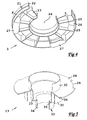
- the odour trap 1 comprises a shell 2 and an end portion 3 releasably connected to the shell 2, which together form a house.
- the shell 2 comprises an end portion or a roof 4, from which a cross-section-wise circular wall shell 5 extends, which widens in the direction from the roof 4 to a lower end, which forms a seat 6 for the end portion 3.
- the seat 6 On the inside of the wall shell 5, the seat 6 includes a circumferential score 7, which co-operates with a corresponding circumferential ridge 8, which runs along the periphery of the end portion 3 (see also figures 3 and 4).
- the odour trap 1 comprises a tubular filter in its entirety designated 9, which in a mounted state extends between the roof 4 and the end portion 3.
- the filter 9 includes a first, tubular grating 10, which is radially remote from a second, tubular grating 11.
- these gratings 10, 11 are concentrically arranged.
- An adsorbing material is inserted in a space 12, which in the radial direction is limited by the gratings 10 and 11 and in the axial direction by the roof 4 and the end portion 3.
- the odour trap 1 comprises a unit 13, for the connection of the same to a blowpipe (not shown), which projects upward from a well, a refuse storage room or the like.
- FIG. 3 In the roof 4 of the shell 2, two ring-shaped grooves 14 and 15 are arranged, in which the upper ends of the gratings 10, 11 are insertable.
- the groove 14 is delimited by the wall shell 5 and a collar 16, which is concentric with the wall shell 5 and projects from the roof 4 in the direction of the lower end of the shell 2.
- the groove 15 is defined in the similar way by two concentric collars 17, 18, which project from the roof 4 in the axial direction downward. The purpose of the collars 16, 17, 18 is to position the gratings 10, 11 and orientate the same in the desired direction.
- the thickness of the gratings 10, 11 is somewhat larger than the width of the grooves 14, 15, so that the gratings by press fit should be kept in the respective groove.
- a border 19 projects from the roof 4, more precisely in the space 12. The function of the border 19 is to prevent the possibility of the formation of a free passage in the filter 9, if the adsorbing material, which is placed in the space 12, would collapse. Therefore, on one hand, the border 19 should protrude at least 15 mm, preferably at least 25 mm. On the other hand, the border 19 should maximally protrude 40 mm, preferably maximally 30 mm, since the border 19 also intrudes on the flow area of the filter 9 and thereby limits the amount of air that can pass through the filter 9.
- a number of axial scores 20 are arranged, preferably three, which co-operate with a corresponding number of ridges 21, which extend axially along the periphery of the end portion 3 (see figure 4).
- the end portion 3 comprises a border 22, on the outside of which the axial ridges 21 and the circumferential ridge 8 are arranged.
- a ring-shaped profile 23 is arranged, which has an essentially U-shaped cross-section.
- the profile 23 is oriented in such a way that the opening in the U-shaped profile, when the end portion 3 is mounted in the shell 2, is directed toward the roof 4 (see figure 2).
- the purpose of the profile 23 is to position the lower end of the filter 9, the U-shaped opening of the profile 23 corresponding with the thickness of the filter 9.
- a central inlet opening 24 is formed, through which the air can flow into the odour trap 1.
- the profile 23 and the border 22 define together a ring-shaped outlet opening 26, through which the air can flow out of the odour trap 1.
- a number of equidistantly spaced-apart reinforcing elements 25 extend, which connect the border 22 and the profile 23 to each other.
- three equidistantly remote lock plates 27 are also connected, which extend radially inward from the border 22 and the common horizontal, extension plane of which is arranged on a level below the border 22 and the reinforcing elements 25.
- the lock plates 27 are arranged to co-operate with the connection unit 13, like a bayonet fitting.
- the connection unit 13 comprises a pipe, generally designated 32, and a brim 28 protruding from the pipe 32, which brim in the periphery thereof has three recesses 29, for the co-operation with the lock plates 27 in the end portion 3.
- a part pipe 30 included in the pipe 32 extends, the outer diameter of which is smaller than the diameter of the inlet opening 24, the part pipe being insertable in said inlet opening 24.
- a pipe socket 31 protrudes, which is radially distanced from the pipe 32.
- the pipe 32 includes two part pipes 33 and 34, which are axially spaced-apart by a flange 35.
- the part pipe 33 closest to the brim 28 has a larger outer diameter than the part pipe 34.
- the outer diameter of the part pipe 34 is about 50 mm, the outer diameter of the part pipe 33 about 75 mm, and the outer diameters of the pipe socket 31 about 110 mm, in order to allow the unit to be connected to blowpipes of conventional standard dimensions.
- the above-mentioned part pipes 33, 34 and the pipe socket 31 may have other suitable outer diameters, which fit blowpipes having other standard measures.
- FIG 6 shows two flexible, uniform grating elements 37, positioned in order to be assembled together.
- the interior tubular grating 11 includes four grating elements 37, and the outer grating 10 seven grating elements 37.
- Each individual grating element 37 comprises two parallel side pieces 40, 41, between which a first set of thin, transverse rods 39 extend. Parallel to the side pieces 40, 41, a second set of thin rods 38 extend, which are connected to the first set of rods 39.
- a plurality of, preferably two, holes or openings 43 are arranged in the first side piece 40.
- the holes 43 co-operate with a corresponding number of hooks 44, arranged on the second side piece 41 of an adjacent grating element 37.
- the hooks 37 are inserted into the holes 43, and then the grating elements 37 are displaced axially in relation to each other and the hooks 44 hook onto the edges of the holes 43.
- FIG. 1 In order to describe a mounting method, reference is now made again primarily to figure 2.
- the shell 2 is turned upside-down, after which the gratings 10 and 11 are pressed down into the grooves 14 and 15, respectively.
- the space 12 is filled with a suitable adsorbing material, for instance activated carbon, potassium permanganate, zeolite, or the like, depending on which smell, or more precisely, which type of evaporated particles that are to be separated from the air.
- the shell 2 is preferably vibrated, in order to make the adsorbing material as compact as possible. However, it should be pointed out that said vibration is not required.
- the end portion 3 When the filter 9 is filled, the end portion 3 is applied in the seat 6, more precisely by the fact that the ridges 21 run axially in the scores 20 and the filter 9 is aligned with the U-shaped opening of the profile 23. By applying an axial force to the end portion 3, the same is pressed down into the seat 6 and the ridge 8 falls down into the score 7. Now, the filter 9 is positioned between the roof 4 and the end portion 3, which turn is secured in the rotary direction as well as the axial direction in relation to the shell 2. The house is now ready to be applied to a blowpipe. Depending on which diameter the blowpipe (not shown) has, either the part pipe 33, the part pipe 34 or the pipe socket 31 of the connection unit 13 may be used.
- the free end of the pipe socket 31 is, in the axial direction, located nearer the brim 28 than the flange 35, which entails that if the pipe socket 31 or the part pipe 33 is to be connected to the blowpipe via, for instance, a sleeve (not shown), the pipe 32 can be cut off on level with the free end of the pipe socket 31, and thereby a larger flow area can be obtained.
- the house Independently of the diameter of the blowpipe, the house can now be applied on the connection unit 13 by the fact that the part pipe 30 is inserted in the inlet opening 24, at the same time as the recesses 29 and the lock plates 27 have to overlap each other.
- a gasket 45 may be applied on the outside of the part pipe 30.
- the bottom sides of the reinforcing elements 25 should be pressed against the top side of the brim 28.
- the house can be rotated in relation to the connection unit 13 so that the lock elements 27 overlap the edge of the brim 28.
- the requisite angle of rotation amounts to about 30°.
- a nib 36 is arranged (see figure 5), which is located in such a way in relation to the recesses 29 that the same is urged over a reinforcing element 25 when the house 13 is rotated in relation to the connection unit 13.
- the purpose of the nib 36 is to counteract that the house shakes loose.
- the house has now an inlet opening 24, which mouths radially inside the interior envelope surface of the filter 9 and which is connected to the blowpipe.
- the house has also an outlet opening 26, which mouths radially outside the outer envelope surface of the filter 9. In other words, air can flow axially into the house via the inlet opening 24, further radially outward through the filter 9, and then again axially out through the outlet opening 26, or vice versa.
- a primary advantage of the separation device according to the invention is that the same, as a consequence of the tubular construction of the filter and the radial direction of flow of the air through the filter, lowers the flow rate of the air through the filter.
- the odour trap according to the invention allows the air to stay relatively long time in the filter.
- Another advantage of the device according to the invention, as a consequence of the filter being tubular, is that a sufficient amount of adsorbing material can be accommodated in the filter without the odour trap becoming disproportionately large. It is also an advantage that the flow area of the filter is many times larger than blowpipes in general, which entails that the filter does not affect or is affected, in a negative way, by high flow rates in the blowpipe.
- the filter does not need to consist of two separate tubular gratings, which in turn consist of a number of grating elements, but the filter may consist of a single cast detail of a similar shape.
- absorption material for the sake of simplicity has been used, in the description as well as in the subsequent claims, it should be appreciated that also absorption or similar reactions and/or oxidations are regarded to be included without deviating from the general idea according to the invention.
- adsorbing material herein should be interpreted in the widest sense thereof, and accordingly be regarded to include each form of component having the capability of fulfilling the purpose of separating one or more types of evaporated particles from air.
- the concept of air has also been used for the sake of simplicity and should be regarded herein to be synonymous with gas.
- the different part components of the odour trap preferably are manufactured from one and the same sort of plastic, in order to facilitate recycling of the odour trap.
- An alternative field of application of such a separation device is in museum showcases, in which pollutants should be separated from the air that is let into the same.
Landscapes
- Chemical & Material Sciences (AREA)
- Engineering & Computer Science (AREA)
- Analytical Chemistry (AREA)
- General Chemical & Material Sciences (AREA)
- Oil, Petroleum & Natural Gas (AREA)
- Chemical Kinetics & Catalysis (AREA)
- Filtering Of Dispersed Particles In Gases (AREA)
- Separating Particles In Gases By Inertia (AREA)
Applications Claiming Priority (2)
| Application Number | Priority Date | Filing Date | Title |
|---|---|---|---|
| SE0400591 | 2004-03-09 | ||
| SE0400591A SE528207C2 (sv) | 2004-03-09 | 2004-03-09 | Anordning för avskiljning av förångade partiklar från en gas |
Publications (2)
| Publication Number | Publication Date |
|---|---|
| EP1574245A2 true EP1574245A2 (de) | 2005-09-14 |
| EP1574245A3 EP1574245A3 (de) | 2006-07-05 |
Family
ID=32067357
Family Applications (1)
| Application Number | Title | Priority Date | Filing Date |
|---|---|---|---|
| EP05004616A Withdrawn EP1574245A3 (de) | 2004-03-09 | 2005-03-03 | Vorrichtung zur Entfernung von Gerüchen aus einem Gas |
Country Status (2)
| Country | Link |
|---|---|
| EP (1) | EP1574245A3 (de) |
| SE (1) | SE528207C2 (de) |
Family Cites Families (5)
| Publication number | Priority date | Publication date | Assignee | Title |
|---|---|---|---|---|
| US2706532A (en) * | 1953-03-26 | 1955-04-19 | Adsorption Res Corp | Fluid treating apparatus |
| US2861651A (en) * | 1957-10-07 | 1958-11-25 | Jefferson Lake Sulphur Co | Cyclic adsorption processes for recovery of h2s from natural gas employing two activation cycles |
| GB2109268B (en) * | 1981-11-16 | 1984-10-03 | Process Scient Innovations | Gas purifiers |
| GB2222534B (en) * | 1988-09-09 | 1992-11-25 | Process Scient Innovations | Filter assembly and cartridge therefor |
| US7127908B2 (en) * | 2000-06-05 | 2006-10-31 | Flow Dry Technology Ltd | Polypropylene or polyester plastic desiccant cartridge with fiberglass filter and bead cage ends |
-
2004
- 2004-03-09 SE SE0400591A patent/SE528207C2/sv not_active IP Right Cessation
-
2005
- 2005-03-03 EP EP05004616A patent/EP1574245A3/de not_active Withdrawn
Also Published As
| Publication number | Publication date |
|---|---|
| SE0400591D0 (sv) | 2004-03-09 |
| SE528207C2 (sv) | 2006-09-26 |
| EP1574245A3 (de) | 2006-07-05 |
| SE0400591L (sv) | 2005-09-10 |
Similar Documents
| Publication | Publication Date | Title |
|---|---|---|
| US10898836B2 (en) | Filter with exterior and interior media components and method of filtering | |
| US4268390A (en) | Storm drain sump filter | |
| AU731091B2 (en) | Filter drainage layer attachment | |
| RU2668911C2 (ru) | Варианты конструкции и конфигурации фильтрующих картриджей, способы сборки и использование | |
| CN109999573B (zh) | 过滤元件、聚结挡板、过滤容器和方法 | |
| JP5379792B2 (ja) | フィルタアセンブリ及び方法 | |
| JPH0235909Y2 (de) | ||
| JPH01310784A (ja) | 濾斗状取入口を有する浄水装置 | |
| JP3148922U (ja) | 雨水濾過器 | |
| US8012226B2 (en) | Air separator and purifier device | |
| AU2004232681A1 (en) | Filter assembly utilizing carbon block and pleated filter element | |
| CA2242990A1 (en) | Elongated filter system, filter element therefor and methods of making same | |
| US7964010B2 (en) | Coalescing filter element | |
| WO2001051172A3 (en) | A filter unit for filtering gas | |
| WO2000076618A1 (en) | Septic tank filtering system | |
| AU627392B2 (en) | Oil filter | |
| US6447680B1 (en) | Double pass septic tank outlet filter | |
| DE102018123413A1 (de) | Flansch, Filtereinsatz, Vorrichtung zum Abscheiden von Ölaerosol aus Luft sowie Verfahren zur Herstellung eines Filtereinsatzes | |
| US7399332B1 (en) | Filter cup | |
| US20010047958A1 (en) | Filter apparatus | |
| JP2640501B2 (ja) | サイクロン分離器 | |
| JP4018948B2 (ja) | フィルタエレメント | |
| JPH0494Y2 (de) | ||
| JPH07194902A (ja) | 混合液の分離装置 | |
| JPH072029Y2 (ja) | ガス吸着用エレメント |
Legal Events
| Date | Code | Title | Description |
|---|---|---|---|
| PUAI | Public reference made under article 153(3) epc to a published international application that has entered the european phase |
Free format text: ORIGINAL CODE: 0009012 |
|
| AK | Designated contracting states |
Kind code of ref document: A2 Designated state(s): AT BE BG CH CY CZ DE DK EE ES FI FR GB GR HU IE IS IT LI LT LU MC NL PL PT RO SE SI SK TR |
|
| AX | Request for extension of the european patent |
Extension state: AL BA HR LV MK YU |
|
| RTI1 | Title (correction) |
Free format text: A DEVICE FOR REMOVING ODOURS FROM A GAS |
|
| PUAL | Search report despatched |
Free format text: ORIGINAL CODE: 0009013 |
|
| AK | Designated contracting states |
Kind code of ref document: A3 Designated state(s): AT BE BG CH CY CZ DE DK EE ES FI FR GB GR HU IE IS IT LI LT LU MC NL PL PT RO SE SI SK TR |
|
| AX | Request for extension of the european patent |
Extension state: AL BA HR LV MK YU |
|
| RIC1 | Information provided on ipc code assigned before grant |
Ipc: B01D 53/04 20060101ALI20060531BHEP Ipc: B01D 53/58 20060101ALI20060531BHEP Ipc: B01D 53/02 20060101AFI20050712BHEP |
|
| 17P | Request for examination filed |
Effective date: 20061228 |
|
| AKX | Designation fees paid |
Designated state(s): AT BE BG CH CY CZ DE DK EE ES FI FR GB GR HU IE IS IT LI LT LU MC NL PL PT RO SE SI SK TR |
|
| 17Q | First examination report despatched |
Effective date: 20070921 |
|
| STAA | Information on the status of an ep patent application or granted ep patent |
Free format text: STATUS: THE APPLICATION HAS BEEN WITHDRAWN |
|
| 18W | Application withdrawn |
Effective date: 20081210 |