EP1573290B1 - Procede permettant de mesurer les proprietes caracteristiques d'un pneumatique pour roues de vehicules - Google Patents
Procede permettant de mesurer les proprietes caracteristiques d'un pneumatique pour roues de vehicules Download PDFInfo
- Publication number
- EP1573290B1 EP1573290B1 EP02808282.4A EP02808282A EP1573290B1 EP 1573290 B1 EP1573290 B1 EP 1573290B1 EP 02808282 A EP02808282 A EP 02808282A EP 1573290 B1 EP1573290 B1 EP 1573290B1
- Authority
- EP
- European Patent Office
- Prior art keywords
- tyre
- sensors
- footprint area
- pneumatic tyre
- array
- Prior art date
- Legal status (The legal status is an assumption and is not a legal conclusion. Google has not performed a legal analysis and makes no representation as to the accuracy of the status listed.)
- Expired - Lifetime
Links
- 238000000034 method Methods 0.000 title claims description 29
- 238000009826 distribution Methods 0.000 claims description 40
- 230000033001 locomotion Effects 0.000 claims description 31
- 238000003491 array Methods 0.000 claims description 10
- 238000005096 rolling process Methods 0.000 description 20
- 238000005259 measurement Methods 0.000 description 12
- 238000001514 detection method Methods 0.000 description 11
- 238000012360 testing method Methods 0.000 description 8
- 238000005070 sampling Methods 0.000 description 5
- 230000003068 static effect Effects 0.000 description 5
- 238000004519 manufacturing process Methods 0.000 description 4
- 238000012545 processing Methods 0.000 description 4
- 230000003321 amplification Effects 0.000 description 3
- 238000003199 nucleic acid amplification method Methods 0.000 description 3
- 230000036316 preload Effects 0.000 description 3
- 239000010453 quartz Substances 0.000 description 3
- VYPSYNLAJGMNEJ-UHFFFAOYSA-N silicon dioxide Inorganic materials O=[Si]=O VYPSYNLAJGMNEJ-UHFFFAOYSA-N 0.000 description 3
- 238000004458 analytical method Methods 0.000 description 2
- 238000004364 calculation method Methods 0.000 description 2
- 239000000463 material Substances 0.000 description 2
- 230000004044 response Effects 0.000 description 2
- 229910000831 Steel Inorganic materials 0.000 description 1
- 230000005540 biological transmission Effects 0.000 description 1
- 230000008859 change Effects 0.000 description 1
- 239000012141 concentrate Substances 0.000 description 1
- 230000001276 controlling effect Effects 0.000 description 1
- 230000002596 correlated effect Effects 0.000 description 1
- 238000013461 design Methods 0.000 description 1
- 230000000694 effects Effects 0.000 description 1
- 230000010354 integration Effects 0.000 description 1
- 239000011159 matrix material Substances 0.000 description 1
- 238000012986 modification Methods 0.000 description 1
- 230000004048 modification Effects 0.000 description 1
- 238000012544 monitoring process Methods 0.000 description 1
- 238000003825 pressing Methods 0.000 description 1
- 238000011160 research Methods 0.000 description 1
- 239000010959 steel Substances 0.000 description 1
- 230000004936 stimulating effect Effects 0.000 description 1
- 239000000126 substance Substances 0.000 description 1
- 230000007704 transition Effects 0.000 description 1
- 238000009827 uniform distribution Methods 0.000 description 1
- 238000011144 upstream manufacturing Methods 0.000 description 1
Images


Classifications
-
- B—PERFORMING OPERATIONS; TRANSPORTING
- B60—VEHICLES IN GENERAL
- B60C—VEHICLE TYRES; TYRE INFLATION; TYRE CHANGING; CONNECTING VALVES TO INFLATABLE ELASTIC BODIES IN GENERAL; DEVICES OR ARRANGEMENTS RELATED TO TYRES
- B60C23/00—Devices for measuring, signalling, controlling, or distributing tyre pressure or temperature, specially adapted for mounting on vehicles; Arrangement of tyre inflating devices on vehicles, e.g. of pumps or of tanks; Tyre cooling arrangements
-
- G—PHYSICS
- G01—MEASURING; TESTING
- G01L—MEASURING FORCE, STRESS, TORQUE, WORK, MECHANICAL POWER, MECHANICAL EFFICIENCY, OR FLUID PRESSURE
- G01L1/00—Measuring force or stress, in general
- G01L1/16—Measuring force or stress, in general using properties of piezoelectric devices
-
- G—PHYSICS
- G01—MEASURING; TESTING
- G01L—MEASURING FORCE, STRESS, TORQUE, WORK, MECHANICAL POWER, MECHANICAL EFFICIENCY, OR FLUID PRESSURE
- G01L17/00—Devices or apparatus for measuring tyre pressure or the pressure in other inflated bodies
- G01L17/005—Devices or apparatus for measuring tyre pressure or the pressure in other inflated bodies using a sensor contacting the exterior surface, e.g. for measuring deformation
-
- G—PHYSICS
- G01—MEASURING; TESTING
- G01M—TESTING STATIC OR DYNAMIC BALANCE OF MACHINES OR STRUCTURES; TESTING OF STRUCTURES OR APPARATUS, NOT OTHERWISE PROVIDED FOR
- G01M17/00—Testing of vehicles
- G01M17/007—Wheeled or endless-tracked vehicles
- G01M17/02—Tyres
- G01M17/021—Tyre supporting devices, e.g. chucks
Definitions
- the present invention in its most general aspect, relates to- a method for measuring characteristic properties of a pneumatic tyre for vehicle wheels. More specifically, the invention relates to a method for detecting the size of the footprint area of a pneumatic tyre for vehicle wheels in high-speed motion conditions, and the distribution of pressure on such a footprint area.
- characteristic properties of a pneumatic tyre is used to indicate, for example, the dimensions and/or the shape of the footprint area of the tyre, the distribution of pressure (or vertical forces) acting locally on the footprint area of the tyre, the tyre inflation pressure, the distribution of longitudinal and/or lateral forces acting on the tyre and the rolling resistance.
- footprint area is used to indicate that zone of the tyre wherein the exchange of forces between the tyre and the road surface (or between the tyre and a device simulating the road surface, such as a rolling runway' of a drum simulating the road surface) takes place, i.e. that zone of the tyre which is in contact with the road surface (or with the device simulating the road surface).
- high-speed is used to indicate a speed greater than 30 km/h, preferably greater than 100 km/h, even more preferably greater than 200 km/h.
- a properly designed tyre has a wide, rectangular or square footprint area which substantially does not change as the rolling speed of the tyre changes.
- a properly designed tyre has a substantially uniform distribution of pressure between the shoulders and the center of the tyre, such a distribution being also substantially invariable as the rolling speed of the tyre varies.
- US 5,749,984 discloses a method for monitoring a tyre wherein a measurement of the size of the footprint area of the tyre is carried out by a sensor suitably housed inside the tyre.
- the sensor is a piezoelectric element which deforms when the tyre comes into contact with the ground thus generating an electrical signal proportional to the speed of deformation thereof.
- the position of the sensor inside the tyre is described as being particularly critical for generating a suitable electrical signal.
- this system is an invasive detection system (i.e. the sensor is provided inside the tyre) and thus it involves complication in the production process of the tyre, as well as it requires the production of tyres ad hoc.
- the Applicant has also verified that a system as the one described in the patent identified above does not allow the actual duration of contact between tyre and road, and therefore the length of the footprint area of the tyre, to be determined with precision. Indeed, the signal generated by the sensor is influenced by phenomena which take place before or after the tyre contacts the road.
- the Applicant has also observed that such a patent does not provide any indication of the shape of the tyre footprint, nor of the distribution of pressure on the footprint area.
- a non-invasive system for detecting the distribution of pressure on the footprint area of a tyre under almost static conditions is disclosed in patent application EP 0 656 269 .
- Such a system provides for the use of a plurality of arrays of load sensors directly applied on the road surface. Such sensors directly measure the vertical forces acting upon the footprint area of the tyre and generate an electrical signal proportional to such forces.
- the Applicant observes that, in line with the disclosure of the aforementioned document, such a system is capable of detecting the distribution of pressure for static conditions or for rolling speeds of the tyre lower than 5-6 Km/h, greater speeds being ruled out due to the limited and/or insufficient frequency response of the load sensors.
- the Applicant has faced the problem of detecting one or more characteristic properties of a pneumatic tyre (such' as the size and/or shape of the footprint area and the distribution of pressure on the footprint area) in high-speed motion conditions (such as 100 km/h) by a non-invasive system and in generic operating conditions of the tyre and has perceived and verified that such a problem is solved by measuring the speed of deformation of at least one array of deformable sensors (i.e.
- the speed of the impact between tyre and sensors and therefore the variation of pressure on the sensors and subsequently deriving from such a measurement, through simple calculation operations and/or simple detections or analyses of the measurement signal, the desired characteristic properties of the tyre (such as the length of the footprint area or the distribution of pressure on the footprint area).
- the present invention in a general aspect thereof, relates to a method for measuring characteristic properties of a pneumatic tyre for vehicle wheels, according to claim 1.
- motion of a pneumatic tyre is used to indicate any condition of movement of the pneumatic tyre with respect to the road surface or to any device simulating the road surface, such as the rolling runway of a drum simulating the road surface. Therefore, either motion by rolling and slipping or sliding of the tyre are considered. For the sake of simplicity, however, explicit reference will be made to a motion by rolling of the tyre.
- direction transversal to the motion direction of the pneumatic tyre is used to indicate any direction tilted by an angle other than zero with respect to the motion direction of the tyre, and therefore not necessarily a direction perpendicular to the motion direction of the tyre, thus making it possible to analyse the behaviour of the tyre even in slipping or camber conditions.
- explicit reference will be often made to a direction perpendicular to the motion direction of the tyre.
- characteristic properties of a pneumatic tyre is used to indicate any quantity or parameter indicating a specific operating condition of the tyre, such as, for example, the size and/or shape of the footprint area of the tyre, the distribution of pressure on the footprint area, the inflation pressure of the tyre, the distribution of longitudinal and/or lateral forces acting upon the tyre, the rolling resistance.
- a specific operating condition of the tyre such as, for example, the size and/or shape of the footprint area of the tyre, the distribution of pressure on the footprint area, the inflation pressure of the tyre, the distribution of longitudinal and/or lateral forces acting upon the tyre, the rolling resistance.
- explicit reference will be often made to the size and/or shape of the footprint area of the tyre and/or to the distribution of pressure (vertical forces) on such a footprint area. Any person skilled in the art will, however, understand that the method of the present invention can also be carried out for measuring the other quantities listed above.
- the method of the present invention allows the behaviour of a tyre to be observed even in high-speed motion conditions and in generic operating conditions (for example in rolling, sliding, slipping and camber conditions of the tyre) by a non-invasive detection system, i.e. by sensors provided outside of the tyre.
- the motion speed of the tyre is equal to or greater than 30 km/h, more preferably equal to or greater than 100 km/h, even more preferably equal to or greater than 200 km/h.
- the present invention it is advantageously possible, for example, to determine the length of the footprint area of a tyre, in high-speed motion conditions, for the entire width of the tyre, and to outline the shape of such a footprint area, by simply arranging an array of deformable sensors along a direction transversal to the motion of the tyre and making the tyre pass over such sensors. Upon contacting the tyre, each sensor generates an electrical signal proportional to the speed of deformation of the sensor itself. By analysing such an electrical-signal it is possible to determine the length of the footprint area measured at the position in which the sensor is located. The overall shape and size of the footprint area are obtained by combining the analogue information obtained from the other sensors of the array of sensors.
- the detection system of the present invention thus differs from the currently known non-invasive detection systems, as the one described in the aforementioned patent application EP 0 656 269 , in that a direct measurement of the vertical forces acting upon the footprint area through load sensors is not carried out, but such forces are obtained through a simple calculation operation starting from a measurement of the speed of deformation of deformable sensors.
- the method of the present invention is carried out to determine just the size and/or shape of a footprint area of a pneumatic tyre in high-speed movement.
- the method of the present invention is carried out to determine just the distribution of the pressure acting upon the footprint area of a pneumatic tyre in high-speed movement.
- the method of the present invention is carried out to determine either the size and/or shape of the footprint area of a pneumatic tyre in high-speed movement, and the distribution of pressure acting on such a footprint area.
- the evolution of the size and/or shape of the footprint area and the distribution of pressure as the speed varies is also determined in conditions of rolling, slipping or sliding of the tyre.
- the method of the present invention can also be carried out to determine other characteristic properties of a pneumatic tyre, as for example the inflation pressure thereof, the distribution of longitudinal and/or lateral forces and the rolling resistance.
- a plurality of arrays of sensors are arranged all substantially parallel and transversal to the motion direction x of the pneumatic tyre, so as to obtain a greater resolution in the determination of the size and/or shape of the footprint area of the tyre and/or in- the distribution of pressure on such a footprint area.
- the various arrays of sensors are ordered according to a staggered arrangement so as to obtain the desired resolution by providing a greater number of sensors in a predetermined detection area.
- the deformation sensors used in the method of the present invention comprise piezoelectric elements, such as pieces of piezoelectric cable, or piezoelectric film, or else quartz, in general being suitable for the purposes of the present invention all those materials which, when deformed, produce a concentration of electrical charge and thus an electrical signal (for example, an electrical current or voltage).
- the piezoelectric elements or the quartz do not require an electrical supply, thus simplifying the detection system of the present invention.
- the deformation sensors comprise piezoelectric cables which scan be directly pressed by the tyre or, alternatively, by a plunger upon which the tyre impacts.
- Such sensors can be directly housed in- a. suitable seat provided on the road surface (in case of outdoor measurements) or on a rolling runway of a drum simulating the road surface (in case of indoor measurements).
- the sensors are previously associated with a support plate which is then adapted to be housed on the road surface or on the drum simulating the road surface. This simplifies and accelerates the assembly, disassembly and adjustment operations of the individual sensors.
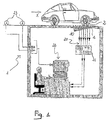
- a system for measuring characteristic properties of a tyre 2 for vehicle wheel in high-speed movement in accordance with the method of the present invention, is indicated with 1.
- the tyre 2 moves at a speed greater than 30 km/h, more preferably equal to or greater than 100 km/h and even more preferably equal to or greater than 200 km/h.
- the system 1 allows one or more characteristic properties of the tyre 2 to be detected in order to evaluate the behaviour of the tyre in generic operating conditions.
- Such properties are, for example, the size and/or shape of the footprint area of the tyre, the distribution of pressure on the footprint area, the inflation pressure of the tyre, the distribution of longitudinal and/or lateral forces acting upon the tyre, the rolling resistance.
- the size and/or shape of the footprint area of the tyre and the distribution of pressure (of the vertical forces) on such a footprint area we shall consider just the size and/or shape of the footprint area of the tyre and the distribution of pressure (of the vertical forces) on such a footprint area.
- the system 1 which actuates the method of the present invention allows to carry out either outdoor measurements ( figure 1 ) and indoor measurements ( figure 2 ).
- the system 1 comprises a plurality of arrays of deformable sensors (all indicated with 10 in figures 1 , 2 and 3 ).
- ten arrays of sensors 10 are represented, whereas in figures 2 and 3 just two arrays of sensors are represented.
- the arrays of sensors 10 are associated with a quadrangular support plate 3 (visible in figures 2 and 3 ) adapted to be housed in a suitable seat 4 formed on the road surface (in case of outdoor measurements, see figure 1 ) or on a rolling runway 5 of a drum 6 simulating the road surface (in case of indoor measurements, see figure 2 ).
- the plate 3 is suitably calendared within the seat 4 formed on the drum 6.
- the arrays of sensors are all arranged parallel along a direction y transversal, perpendicular in the illustrated example, to the motion direction x of the tyre 2 and extend along the direction y for a length at least equal to the dimension of the tyre 2 along said direction y.
- the arrangement of the various arrays of sensors 10 on the plate 3 is staggered along the direction y.
- the sensors 10 are, in particular, deformation sensors, i.e. elements having the capability to concentrate electrical charges when subjected to deformation and then generate an electrical signal proportional to such a deformation.
- each of the sensors 10 comprises a piezoelectric element which is subjected to deformation as the tyre 2 passes over the sensor and generates an electrical signal proportional to the speed of deformation, i.e. to the speed of impact with the tyre 2, or in other words to the variation of pressure undergone by the sensor 10.
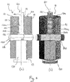
- the sensor 10 comprises a main body 11 in which a longitudinal through-hole 12, a longitudinal threaded through-hole 13 and a transversal through-hole 14 are formed.
- the through-hole 12 is formed at an upper portion of the main body 11 and has two portions of hole 12a and 12b, upper and lower respectively, with a different diameter, the portion of hole 12b having a diameter greater than that of the portion of hole 12a.
- the threaded hole 13 is formed coaxially to the hole 12 at a lower portion of the main body 11.
- the transversal hole 14 is placed between the through-hole 12 and the threaded hole 13.
- a plunger 120 made of steel is slidably housed in the through-hole 12.
- the plunger 120 comprises a first plunger portion 120a slidably housed in the portion of hole 12a, and a second plunger portion 120b with a greater diameter slidably housed in the portion of hole 12b.
- a piezoelectric cable 140 which constitutes the deformable element of the sensor 10, is housed in the transversal hole 14. Such a cable is held always in contact with the plunger 120 by means of a preload screw 130 housed in the threaded hole 13.
- annular crown 110 is defined which is suitable for acting as an abutment surface for the plunger portion 120b.
- the annular crown 110 thus constitutes a mechanical stop for the plunger 120 which is thus prevented from escaping from the main body 11 through the portion of hole 12a.
- the plunger 120 is sized so that, when the plunger portion 120b abuts upon the annular crown 110 of the body 11, an end portion 121 of the plunger 120 slightly protrudes from the upper face 11a of the main body 11, whereas the lower plunger portion 120b contacts the piezoelectric cable 140.
- the tyre 2 when passing on the sensor 10, impacts with the upper portion 121 of the plunger 120.
- the plunger is thus pushed to slide downwards, thus pressing upon the piezoelectric cable 140 which is thus deformed and which generates an electrical signal proportional to the speed of deformation, i.e. to the variation of pressure undergone.
- the assembly of the sensor 10 takes place by firstly inserting the plunger 120 in the through-hole 12 through the threaded hole 13, then inserting the piezoelectric cable 140 in the transversal hole 14 and finally screwing the preload screw 130 into the hole 13 till the plunger 120 abuts the annular crown 110 of the main body 11 and gives the piezoelectric cable 140 the correct static preload.
- the main body 11 has an outer threading 111 suitable for allowing the screwing of the sensor 10 into the plate 3.
- the body 11 consists of a hollow screw.
- the piezoelectric cable 140 is arranged in a groove formed on the head of a screw which is in turn associated with the plate 3, or directly with the road surface or with the drum simulating the road surface, so as to be pressed directly by the tyre 2.
- a structural configuration of the sensor 10 is, however, less preferred with respect to the one described above which provides for the use of the plunger 120. This last configuration, indeed, ensures less distorted signals, greater amplifications and less wear of the piezoelectric cable 140.
- the detection of the size and/or shape of the footprint area of a tyre takes place in the following way.
- each sensor 10 In outdoor detection systems (see figure 1 ), the vehicle which carries the tyre 2 is made to pass over the sensors 10 which are previously housed in the road surface. Upon contact with the tyre 2, each sensor 10 generates an electrical signal proportional to the speed of deformation.
- the electrical signals obtained by the various sensors 10 are transmitted, through screened cables 20 suitably associated with the sensors 10 (and preferably through an amplification system 21) to a digital acquisition card of a data processing station 22, which takes care of extracting the desired information from the signals.
- the speed of the tyre 2 is detected through photocells 23 provided upstream of the sensors 10 along the motion direction x of the tyre 2.
- the signal generated by the photocells 23 is sent to the data processing station 22.
- the sensors 10 are housed on- the rolling runway 5 of a drum 6 stimulating the road surface.
- the tyre 2 is fitted onto the hub of a dynamometric rod 30 and is brought into contact with the drum 6 while controlling the vertical load, the slip and the camber.
- the rolling of the tyre 2 takes the sensors 10 into contact with the tyre 2, thus generating the electrical signals.
- the' electrical signals obtained by the various sensors 10 are transmitted, through screened cables 20 suitably associated with the sensors 10 and connected through a rotary collector 20a, to a digital acquisition card of a data processing station 22, which takes care of extracting the desired information from the signals.
- the signals are first amplified by an amplification system 21.
- the electrical signal generated by each sensor 10 typically has a trend which from zero rapidly reaches a maximum amplitude (MAX) at a zone of first contact between sensor and tyre and, after a transition phase, a minimum amplitude (MIN) at a zone of end of contact between sensor and tyre.
- MAX maximum amplitude
- MIN minimum amplitude
- the overall shape and size of the footprint area are obtained by combining the analogue information obtained from the other sensors 10 arranged at different positions on the footprint. Since the signal emitted by each signal 10 is proportional to the speed of deformation thereof, and therefore to the variation of pressure on the sensor, an index of distribution of pressure on the footprint area of the tyre 2 is obtained by integrating such a signal in time. With the integrals coming from the other sensors the distribution of pressure on the whole of the footprint area of the tyre 2 is then determined.
- the Applicant has carried out a series of tests to detect the size and shape of the footprint area of a tyre, the distribution of pressure on such a footprint area and the evolution of such properties as the inflation pressure of the tyre, its motion speed and the vertical load vary. Analogous tests have been carried out to measure characteristic properties of a tyre in conditions of right and left slip.
- An indoor detection system of the type described in figure 2 was used. Seven sensors, of the type illustrated in figures 3 to 5 , were arranged in an array on a rolling runway of a drum simulating the road surface. The tyre to be monitored was mounted onto a dynamometric rod and was brought into contact with the drum. The tyre was made to rotate initially at a speed of 30 Km/h. The vertical load on the contact area between tyre and drum simulating the road surface was initially 3.000 N.
- the signal obtained by each sensor had a trend as a function of time as illustrated in figure 6 .
- the time in seconds is shown and along the Y-axis the electrical signal in Volts is shown.
- the length of the footprint area at each sensor was determined by measuring the spatial distance between the point of maximum amplitude and the point of minimum amplitude of the signal and by multiplying such a distance by the speed of rotation of the tyre.
- the overall shape and size of the footprint area were obtained by combining the analogue information of the other sensors of the array.
- the graph of figure 7 represents the signal (V) emitted by a sensor as a function of the number of sampling points (given the frequency of sampling a matrix of times is reconstructed and, knowing the motion speed of the tyre, the space vector is reconstructed) for six linearly increasing loads (Q) expressed in Newton.
- the graph of figure 8 shows the signals of figure 7 integrated numerically based upon the vector number of sampling points (Volts per unit).
- the graph of figure 9 represents the length (a) in metres of the measured footprint at a sensor for six increasing loads (Q) expressed in Newton. It can be seen how the length of the footprint increases as the vertical load increases.
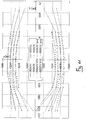
- the graph of figure 10 shows the map of the footprint area considering all of the sensors of the array and for eight increasing vertical loads.
- the position (b) of the various sensors (in metres) along the array (and therefore the width of the footprint area) is shown and along the Y-axis the length (a) of the footprint area (in metres) at each sensor is shown, whereas the variation parameter is the vertical load expressed in Newton (N).
- N the vertical load expressed in Newton
- Such a graph substantially shows the shape and size (length (a) and width (b)) of the footprint area of the tyre for eight different loads. It can be seen how the footprint area increases as the vertical load increases.
- the graph of figure 12 shows a three-dimensional map of the distribution of pressure on the footprint area.
- the horizontal axes show the position (b) of the sensors in the array (and thus the width of the footprint area) and the length (a) of the footprint area at each sensor.
- the vertical axis shows the' signals of figure 7 integrated numerically based upon the vector number of sampling points- (Volts per unit). The effect of a small camber angle should be noted: on the right there is a significant distribution of pressure.
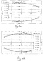
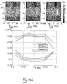
- the graphs of figures 13a and 13b show the evolution of the size (length (a) and width (b)) of the footprint for a right and left slip test, respectively, for different slip angles expressed in radians.
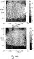
- the maps of figures 14a and 14b show the map of distribution of pressure on the footprint area for a 2 degree right and left slip test, respectively. The specular behaviour of the footprint is clear.
- Figures 15a, 15b, 15c show the maps of distribution of pressure on the footprint area for three increasing levels of inflation pressure expressed in Pascal (Pa) and figure 15d shows the relative shapes of the footprint area. It can be seen how the footprint area reduces as the inflation pressure increases, with a constant vertical load.
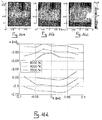
- Figures 16a, 16b, 16c show the maps of distribution of pressure on the footprint area for three increasing levels of vertical load expressed in Newton (N) and figure 16d shows the relative shapes of the footprint area. It can be seen how the footprint area increases as the vertical load increases.
- Figures 17a, 17b, 17c show the maps of distribution of pressure on the footprint area for three increasing levels of motion speed (V1, V2, V3, equal to 50, 100, 150 Km/h, respectively) and figure 17d shows the relative shapes of the footprint area.
- the transmission of the signals from the sensors 10 to the data processing station 22 can be carried out through radio frequency transmitters.
Landscapes
- Physics & Mathematics (AREA)
- General Physics & Mathematics (AREA)
- Engineering & Computer Science (AREA)
- Mechanical Engineering (AREA)
- Chemical & Material Sciences (AREA)
- Analytical Chemistry (AREA)
- Force Measurement Appropriate To Specific Purposes (AREA)
- Tires In General (AREA)
- Measuring Fluid Pressure (AREA)
Claims (8)
- Procédé de mesure de propriétés caractéristiques d'un pneumatique pour roues de véhicule, comprenant les étapes qui consistent :- à agencer au moins un réseau de capteurs déformables (10) le long d'une direction y transversale à une direction de déplacement x d'un pneumatique (2) pour des roues de véhicule, ledit au moins un réseau de capteurs (10) s'étendant sur une longueur qui est au moins égale à la dimension dudit pneumatique (2) le long de ladite direction y ;- à laisser passer ledit pneumatique (2) sur ledit au moins un réseau de capteurs (10) le long de ladite direction de déplacement x à une vitesse supérieure ou égale à 30 Km/h ;- à générer, pour chaque capteur (10) dudit au moins un réseau de capteurs (10), un signal électrique proportionnel à une vitesse de déformation desdits capteurs (10) lorsqu'ils entrent en contact avec ledit pneumatique (2) ;- à détecter ledit signal électrique généré par chaque capteur (10) dudit au moins un réseau de capteurs (10) ;- à déterminer, en partant de chaque signal électrique détecté, au moins une propriété caractéristique dudit pneumatique (2).
- Procédé selon la revendication 1, dans lequel ladite au moins une propriété caractéristique dudit pneumatique (2) est la taille d'une zone d'empreinte dudit pneumatique (2) le long de ladite direction de déplacement x.
- Procédé selon la revendication 1 ou 2, dans lequel ladite au moins une propriété caractéristique dudit pneumatique (2) est la forme de ladite zone d'empreinte.
- Procédé selon l'une quelconque des revendications précédentes, dans lequel ladite au moins une propriété caractéristique est la répartition de la pression agissant sur la zone d'empreinte dudit pneumatique (2).
- Procédé selon l'une quelconque des revendications précédentes, comprenant l'étape qui consiste à agencer une pluralité de réseaux de capteurs (10) tous essentiellement parallèles et transversaux à ladite direction de déplacement x dudit pneumatique (2).
- Procédé selon l'une quelconque des revendications précédentes, dans lequel l'étape d'agencement dudit au moins un réseau de capteurs déformables (10) comprend l'étape qui consiste à recevoir ledit au moins un réseau de capteurs (10) dans un siège formé sur un tambour (6) d'une roue simulant la surface de la route.
- Procédé selon l'une quelconque des revendications 1 à 5, dans lequel l'étape d'agencement dudit au moins un réseau de capteurs déformables (10) comprend l'étape qui consiste à recevoir ledit au moins un réseau de capteurs (10) dans un siège (4) formé sur une surface de la route.
- Procédé selon l'une quelconque des revendications précédentes, dans lequel l'étape d'agencement dudit au moins un réseau de capteurs déformables (10) comprend l'étape qui consiste à associer ledit au moins un réseau de capteurs (10) à une plaque de support (3).
Applications Claiming Priority (1)
| Application Number | Priority Date | Filing Date | Title |
|---|---|---|---|
| PCT/IT2002/000815 WO2004057292A1 (fr) | 2002-12-20 | 2002-12-20 | Procede permettant de mesurer les proprietes caracteristiques d'un pneumatique pour roues de vehicules |
Publications (2)
| Publication Number | Publication Date |
|---|---|
| EP1573290A1 EP1573290A1 (fr) | 2005-09-14 |
| EP1573290B1 true EP1573290B1 (fr) | 2017-11-08 |
Family
ID=32676770
Family Applications (1)
| Application Number | Title | Priority Date | Filing Date |
|---|---|---|---|
| EP02808282.4A Expired - Lifetime EP1573290B1 (fr) | 2002-12-20 | 2002-12-20 | Procede permettant de mesurer les proprietes caracteristiques d'un pneumatique pour roues de vehicules |
Country Status (6)
| Country | Link |
|---|---|
| US (1) | US7222522B2 (fr) |
| EP (1) | EP1573290B1 (fr) |
| CN (1) | CN100381802C (fr) |
| AU (1) | AU2002368498A1 (fr) |
| BR (2) | BRPI0215984B1 (fr) |
| WO (1) | WO2004057292A1 (fr) |
Families Citing this family (26)
| Publication number | Priority date | Publication date | Assignee | Title |
|---|---|---|---|---|
| GB0415258D0 (en) | 2004-07-07 | 2004-08-11 | Wheelright Ltd | Vehicle tyre checking system |
| JP4465506B2 (ja) * | 2004-10-14 | 2010-05-19 | 株式会社神戸製鋼所 | タイヤhilシミュレータ |
| DE102004055701B4 (de) * | 2004-11-18 | 2007-03-15 | Continental Aktiengesellschaft | Verfahren und Vorrichtung zum Erfassen eines Druckes |
| US20070018803A1 (en) * | 2005-07-20 | 2007-01-25 | Lang Daniel O | System for automatically assessing tire condition and method for using same |
| JP4005618B2 (ja) * | 2006-04-14 | 2007-11-07 | 株式会社神戸製鋼所 | タイヤの制動特性試験装置 |
| JP5098092B2 (ja) * | 2006-09-19 | 2012-12-12 | ヴェンテヒ・ゲーエムベーハー | 車輌タイヤ内の圧力及び/又は車輌の速度の検出用システム |
| WO2008034414A1 (fr) * | 2006-09-19 | 2008-03-27 | Ventech Gmbh | Procédé pour déterminer la pression dans un pneumatique de véhicule |
| JP5027549B2 (ja) * | 2007-04-06 | 2012-09-19 | 住友ゴム工業株式会社 | 空気入りタイヤ、及びそれに作用する力の検出方法 |
| US7523656B1 (en) | 2007-11-01 | 2009-04-28 | Infineon Technologies Ag | Tire sensor system and monitoring method |
| US9135479B2 (en) * | 2009-12-17 | 2015-09-15 | The Goodyear Tire & Rubber Company | Antenna assembly for a tag reader |
| US20110148593A1 (en) * | 2009-12-17 | 2011-06-23 | Robert Leon Benedict | Method for reading a vehicle tag within a read station |
| JP2011203207A (ja) * | 2010-03-26 | 2011-10-13 | Bridgestone Corp | タイヤの接地特性の測定方法及び測定装置 |
| US8347703B2 (en) | 2011-02-11 | 2013-01-08 | Bridgestone Americas Tire Operations, Llc | Tire chip and tear test apparatus and method |
| JP5613117B2 (ja) * | 2011-07-20 | 2014-10-22 | 本田技研工業株式会社 | 弾性部材の変形速度演算装置および変形速度演算方法ならびに駆動装置 |
| JP5887224B2 (ja) * | 2012-07-20 | 2016-03-16 | 株式会社ブリヂストン | タイヤの接地特性の測定方法及び測定装置 |
| FR3030742A1 (fr) * | 2014-12-17 | 2016-06-24 | Michelin & Cie | Systeme et procede d'evaluation de l'aire de contact d'un pneumatique |
| GB2533658A (en) * | 2014-12-22 | 2016-06-29 | Continental Automotive Gmbh | Method and system for determining a wheel load acting on a tire of a vehicle |
| US9707806B2 (en) | 2015-02-06 | 2017-07-18 | Love's Travel Stops & Country Stores, Inc. | Vehicle servicing and monitoring method and system |
| JP2018054492A (ja) * | 2016-09-29 | 2018-04-05 | 株式会社Subaru | 車両の荷重分布計測装置 |
| JP6922727B2 (ja) * | 2017-12-26 | 2021-08-18 | 住友ゴム工業株式会社 | タイヤの評価方法 |
| US10942078B2 (en) | 2019-05-31 | 2021-03-09 | TYCKit GmbH | Measurement of pressure in pressure-filled containers with flexible walls, in particular tires |
| US20220291087A1 (en) * | 2019-10-08 | 2022-09-15 | A&D Company, Limited | Tire testing device |
| JP7432346B2 (ja) | 2019-12-04 | 2024-02-16 | 株式会社ブリヂストン | タイヤ接地特性計測装置、タイヤ接地特性計測システム及びタイヤ接地特性計測方法 |
| US11421982B2 (en) | 2020-05-28 | 2022-08-23 | The Goodyear Tire & Rubber Company | System and method for estimating tire tread depth |
| US11413912B2 (en) | 2020-12-15 | 2022-08-16 | The Goodyear Tire & Rubber Company | System and method for temperature compensation of drive over reader pressure measurement |
| WO2022232520A1 (fr) * | 2021-04-30 | 2022-11-03 | Tekscan, Inc. | Capteurs de contact |
Family Cites Families (9)
| Publication number | Priority date | Publication date | Assignee | Title |
|---|---|---|---|---|
| IT1223919B (it) * | 1988-11-18 | 1990-09-29 | Leonardo Fioravanti | Procedimento e sistema per la rilevazione delle impronte di appoggio dei pneumatici di un autoveicolo particolarmente per l'ottimizzazione automatica del comportamento del l'autoveicolo |
| US5269186A (en) * | 1990-12-24 | 1993-12-14 | Ford Motor Company | Apparatus and method for detecting rotational imbalance of vehicle roadwheels |
| US5445020A (en) | 1991-11-29 | 1995-08-29 | Exxon Research And Engineering Company | Tire inflation sensor |
| US5749984A (en) * | 1995-12-29 | 1998-05-12 | Michelin Recherche Et Technique S.A. | Tire monitoring system and method |
| GB9709645D0 (en) * | 1997-05-14 | 1997-07-02 | Sun Electric Uk Ltd | Tyre pressure determination |
| JP2001056436A (ja) * | 1999-08-19 | 2001-02-27 | Ricoh Co Ltd | ズームレンズ |
| US6561018B2 (en) * | 1999-11-18 | 2003-05-13 | Pirelli Pneumatici S.P.A. | Method and device for monitoring the instantaneous behavior of a tire during the running of a motor vehicle |
| EP2039540B1 (fr) | 2000-03-16 | 2012-01-11 | Pirelli Tyre S.p.A. | Procédé pour déterminer le comportement d'un pneu en mouvement |
| US7646195B2 (en) * | 2003-09-02 | 2010-01-12 | Infineon Technologies Ag | Apparatus and method for sensing rotation of a wheel |
-
2002
- 2002-12-20 EP EP02808282.4A patent/EP1573290B1/fr not_active Expired - Lifetime
- 2002-12-20 WO PCT/IT2002/000815 patent/WO2004057292A1/fr not_active Application Discontinuation
- 2002-12-20 US US10/535,309 patent/US7222522B2/en not_active Expired - Lifetime
- 2002-12-20 AU AU2002368498A patent/AU2002368498A1/en not_active Abandoned
- 2002-12-20 BR BRPI0215984A patent/BRPI0215984B1/pt unknown
- 2002-12-20 BR BR0215984-8A patent/BR0215984A/pt not_active IP Right Cessation
- 2002-12-20 CN CNB028300807A patent/CN100381802C/zh not_active Expired - Fee Related
Non-Patent Citations (1)
| Title |
|---|
| None * |
Also Published As
| Publication number | Publication date |
|---|---|
| WO2004057292A1 (fr) | 2004-07-08 |
| US20060123897A1 (en) | 2006-06-15 |
| CN1714284A (zh) | 2005-12-28 |
| EP1573290A1 (fr) | 2005-09-14 |
| US7222522B2 (en) | 2007-05-29 |
| BRPI0215984B1 (pt) | 2020-01-21 |
| BR0215984A (pt) | 2005-11-01 |
| CN100381802C (zh) | 2008-04-16 |
| AU2002368498A1 (en) | 2004-07-14 |
Similar Documents
| Publication | Publication Date | Title |
|---|---|---|
| EP1573290B1 (fr) | Procede permettant de mesurer les proprietes caracteristiques d'un pneumatique pour roues de vehicules | |
| JP3567282B2 (ja) | タイヤ圧測定装置 | |
| EP0980511B1 (fr) | Mesure de la pression de pneumatiques | |
| KR101812358B1 (ko) | Wim 센서 교정 방법 | |
| CA2845928C (fr) | Controle de pression de pneu de vehicule | |
| EP2876423B1 (fr) | Procédé et dispositif de mesure des propriétés de contact au sol des pneus | |
| EP1906165B1 (fr) | Procédé et dispositif pour le calcul de l amplitude de la force de dérive générée dans une roue | |
| TR201909485T4 (tr) | Araç lastiği kontrol sistemi. | |
| WO1998040705A9 (fr) | Systeme et procede permettant de peser avec precision et de determiner les caracteristiques de vehicules mobiles | |
| AU2001263694A1 (en) | Devices and methods for determining an inner pressure of the eye | |
| CN110108340B (zh) | 一种汽车动态称重装置 | |
| US5289718A (en) | Apparatus and method for measuring tire force | |
| KR100186829B1 (ko) | 차량 타이어와 도로면 사이의 마찰력 결정 장치 | |
| CN108267246A (zh) | 一种动态胎与路接地应力测量装置及方法 | |
| KR20220117854A (ko) | 타이어 특성의 안전 측정 | |
| KR20170080809A (ko) | 타이어 변형 측정장치 | |
| WO2022229993A1 (fr) | Procédé et système d'étalonnage d'un capteur pour pneus | |
| Lung et al. | A laser-based vision system for tire tread depth inspection | |
| EP3916370A1 (fr) | Capteur de température de pneu, système et procédé de mesure de la température d'un pneumatique | |
| WO2012010943A1 (fr) | Système et procédé pour peser des véhicules en mouvement | |
| EP2878935A1 (fr) | Procédé, système et appareil de pesée dynamique de véhicule routier | |
| CN116499773A (zh) | 一种基于压电薄膜矩阵的轮胎滚动阻力系数测量装置及测量方法 | |
| GB2480306A (en) | Weighing vehicles in motion | |
| KR19980053526U (ko) | 차체 중량 측정장치 |
Legal Events
| Date | Code | Title | Description |
|---|---|---|---|
| PUAI | Public reference made under article 153(3) epc to a published international application that has entered the european phase |
Free format text: ORIGINAL CODE: 0009012 |
|
| 17P | Request for examination filed |
Effective date: 20050520 |
|
| AK | Designated contracting states |
Kind code of ref document: A1 Designated state(s): AT BE BG CH CY CZ DE DK EE ES FI FR GB GR IE IT LI LU MC NL PT SE SI SK TR |
|
| AX | Request for extension of the european patent |
Extension state: AL LT LV MK RO |
|
| DAX | Request for extension of the european patent (deleted) | ||
| RAP1 | Party data changed (applicant data changed or rights of an application transferred) |
Owner name: PIRELLI TYRE S.P.A. |
|
| R17P | Request for examination filed (corrected) |
Effective date: 20050520 |
|
| RAP1 | Party data changed (applicant data changed or rights of an application transferred) |
Owner name: PIRELLI TYRE S.P.A. |
|
| 17Q | First examination report despatched |
Effective date: 20141222 |
|
| GRAP | Despatch of communication of intention to grant a patent |
Free format text: ORIGINAL CODE: EPIDOSNIGR1 |
|
| INTG | Intention to grant announced |
Effective date: 20170517 |
|
| GRAS | Grant fee paid |
Free format text: ORIGINAL CODE: EPIDOSNIGR3 |
|
| GRAJ | Information related to disapproval of communication of intention to grant by the applicant or resumption of examination proceedings by the epo deleted |
Free format text: ORIGINAL CODE: EPIDOSDIGR1 |
|
| GRAL | Information related to payment of fee for publishing/printing deleted |
Free format text: ORIGINAL CODE: EPIDOSDIGR3 |
|
| GRAR | Information related to intention to grant a patent recorded |
Free format text: ORIGINAL CODE: EPIDOSNIGR71 |
|
| GRAA | (expected) grant |
Free format text: ORIGINAL CODE: 0009210 |
|
| INTC | Intention to grant announced (deleted) | ||
| INTG | Intention to grant announced |
Effective date: 20170928 |
|
| AK | Designated contracting states |
Kind code of ref document: B1 Designated state(s): AT BE BG CH CY CZ DE DK EE ES FI FR GB GR IE IT LI LU MC NL PT SE SI SK TR |
|
| REG | Reference to a national code |
Ref country code: GB Ref legal event code: FG4D |
|
| REG | Reference to a national code |
Ref country code: CH Ref legal event code: EP Ref country code: AT Ref legal event code: REF Ref document number: 944587 Country of ref document: AT Kind code of ref document: T Effective date: 20171115 |
|
| REG | Reference to a national code |
Ref country code: IE Ref legal event code: FG4D |
|
| REG | Reference to a national code |
Ref country code: DE Ref legal event code: R096 Ref document number: 60249164 Country of ref document: DE |
|
| REG | Reference to a national code |
Ref country code: FR Ref legal event code: PLFP Year of fee payment: 16 |
|
| REG | Reference to a national code |
Ref country code: NL Ref legal event code: MP Effective date: 20171108 |
|
| REG | Reference to a national code |
Ref country code: AT Ref legal event code: MK05 Ref document number: 944587 Country of ref document: AT Kind code of ref document: T Effective date: 20171108 |
|
| PG25 | Lapsed in a contracting state [announced via postgrant information from national office to epo] |
Ref country code: ES Free format text: LAPSE BECAUSE OF FAILURE TO SUBMIT A TRANSLATION OF THE DESCRIPTION OR TO PAY THE FEE WITHIN THE PRESCRIBED TIME-LIMIT Effective date: 20171108 Ref country code: SE Free format text: LAPSE BECAUSE OF FAILURE TO SUBMIT A TRANSLATION OF THE DESCRIPTION OR TO PAY THE FEE WITHIN THE PRESCRIBED TIME-LIMIT Effective date: 20171108 Ref country code: FI Free format text: LAPSE BECAUSE OF FAILURE TO SUBMIT A TRANSLATION OF THE DESCRIPTION OR TO PAY THE FEE WITHIN THE PRESCRIBED TIME-LIMIT Effective date: 20171108 Ref country code: NL Free format text: LAPSE BECAUSE OF FAILURE TO SUBMIT A TRANSLATION OF THE DESCRIPTION OR TO PAY THE FEE WITHIN THE PRESCRIBED TIME-LIMIT Effective date: 20171108 |
|
| PG25 | Lapsed in a contracting state [announced via postgrant information from national office to epo] |
Ref country code: BG Free format text: LAPSE BECAUSE OF FAILURE TO SUBMIT A TRANSLATION OF THE DESCRIPTION OR TO PAY THE FEE WITHIN THE PRESCRIBED TIME-LIMIT Effective date: 20180208 Ref country code: AT Free format text: LAPSE BECAUSE OF FAILURE TO SUBMIT A TRANSLATION OF THE DESCRIPTION OR TO PAY THE FEE WITHIN THE PRESCRIBED TIME-LIMIT Effective date: 20171108 Ref country code: GR Free format text: LAPSE BECAUSE OF FAILURE TO SUBMIT A TRANSLATION OF THE DESCRIPTION OR TO PAY THE FEE WITHIN THE PRESCRIBED TIME-LIMIT Effective date: 20180209 |
|
| PG25 | Lapsed in a contracting state [announced via postgrant information from national office to epo] |
Ref country code: CY Free format text: LAPSE BECAUSE OF FAILURE TO SUBMIT A TRANSLATION OF THE DESCRIPTION OR TO PAY THE FEE WITHIN THE PRESCRIBED TIME-LIMIT Effective date: 20171108 Ref country code: EE Free format text: LAPSE BECAUSE OF FAILURE TO SUBMIT A TRANSLATION OF THE DESCRIPTION OR TO PAY THE FEE WITHIN THE PRESCRIBED TIME-LIMIT Effective date: 20171108 Ref country code: CZ Free format text: LAPSE BECAUSE OF FAILURE TO SUBMIT A TRANSLATION OF THE DESCRIPTION OR TO PAY THE FEE WITHIN THE PRESCRIBED TIME-LIMIT Effective date: 20171108 Ref country code: DK Free format text: LAPSE BECAUSE OF FAILURE TO SUBMIT A TRANSLATION OF THE DESCRIPTION OR TO PAY THE FEE WITHIN THE PRESCRIBED TIME-LIMIT Effective date: 20171108 Ref country code: SK Free format text: LAPSE BECAUSE OF FAILURE TO SUBMIT A TRANSLATION OF THE DESCRIPTION OR TO PAY THE FEE WITHIN THE PRESCRIBED TIME-LIMIT Effective date: 20171108 |
|
| REG | Reference to a national code |
Ref country code: CH Ref legal event code: PL |
|
| REG | Reference to a national code |
Ref country code: DE Ref legal event code: R097 Ref document number: 60249164 Country of ref document: DE |
|
| PLBE | No opposition filed within time limit |
Free format text: ORIGINAL CODE: 0009261 |
|
| STAA | Information on the status of an ep patent application or granted ep patent |
Free format text: STATUS: NO OPPOSITION FILED WITHIN TIME LIMIT |
|
| REG | Reference to a national code |
Ref country code: IE Ref legal event code: MM4A |
|
| PG25 | Lapsed in a contracting state [announced via postgrant information from national office to epo] |
Ref country code: LU Free format text: LAPSE BECAUSE OF NON-PAYMENT OF DUE FEES Effective date: 20171220 |
|
| 26N | No opposition filed |
Effective date: 20180809 |
|
| REG | Reference to a national code |
Ref country code: BE Ref legal event code: MM Effective date: 20171231 |
|
| GBPC | Gb: european patent ceased through non-payment of renewal fee |
Effective date: 20180208 |
|
| PG25 | Lapsed in a contracting state [announced via postgrant information from national office to epo] |
Ref country code: IE Free format text: LAPSE BECAUSE OF NON-PAYMENT OF DUE FEES Effective date: 20171220 |
|
| PG25 | Lapsed in a contracting state [announced via postgrant information from national office to epo] |
Ref country code: SI Free format text: LAPSE BECAUSE OF FAILURE TO SUBMIT A TRANSLATION OF THE DESCRIPTION OR TO PAY THE FEE WITHIN THE PRESCRIBED TIME-LIMIT Effective date: 20171108 Ref country code: CH Free format text: LAPSE BECAUSE OF NON-PAYMENT OF DUE FEES Effective date: 20171231 Ref country code: LI Free format text: LAPSE BECAUSE OF NON-PAYMENT OF DUE FEES Effective date: 20171231 Ref country code: BE Free format text: LAPSE BECAUSE OF NON-PAYMENT OF DUE FEES Effective date: 20171231 |
|
| PG25 | Lapsed in a contracting state [announced via postgrant information from national office to epo] |
Ref country code: GB Free format text: LAPSE BECAUSE OF NON-PAYMENT OF DUE FEES Effective date: 20180208 |
|
| PG25 | Lapsed in a contracting state [announced via postgrant information from national office to epo] |
Ref country code: MC Free format text: LAPSE BECAUSE OF FAILURE TO SUBMIT A TRANSLATION OF THE DESCRIPTION OR TO PAY THE FEE WITHIN THE PRESCRIBED TIME-LIMIT Effective date: 20171108 |
|
| PGFP | Annual fee paid to national office [announced via postgrant information from national office to epo] |
Ref country code: IT Payment date: 20191219 Year of fee payment: 18 Ref country code: FR Payment date: 20191226 Year of fee payment: 18 |
|
| PG25 | Lapsed in a contracting state [announced via postgrant information from national office to epo] |
Ref country code: TR Free format text: LAPSE BECAUSE OF FAILURE TO SUBMIT A TRANSLATION OF THE DESCRIPTION OR TO PAY THE FEE WITHIN THE PRESCRIBED TIME-LIMIT Effective date: 20171108 |
|
| PGFP | Annual fee paid to national office [announced via postgrant information from national office to epo] |
Ref country code: DE Payment date: 20191231 Year of fee payment: 18 |
|
| PG25 | Lapsed in a contracting state [announced via postgrant information from national office to epo] |
Ref country code: PT Free format text: LAPSE BECAUSE OF FAILURE TO SUBMIT A TRANSLATION OF THE DESCRIPTION OR TO PAY THE FEE WITHIN THE PRESCRIBED TIME-LIMIT Effective date: 20171108 |
|
| REG | Reference to a national code |
Ref country code: DE Ref legal event code: R119 Ref document number: 60249164 Country of ref document: DE |
|
| PG25 | Lapsed in a contracting state [announced via postgrant information from national office to epo] |
Ref country code: IT Free format text: LAPSE BECAUSE OF NON-PAYMENT OF DUE FEES Effective date: 20201220 Ref country code: FR Free format text: LAPSE BECAUSE OF NON-PAYMENT OF DUE FEES Effective date: 20201231 |
|
| PG25 | Lapsed in a contracting state [announced via postgrant information from national office to epo] |
Ref country code: DE Free format text: LAPSE BECAUSE OF NON-PAYMENT OF DUE FEES Effective date: 20210701 |