EP1573277B1 - Anschlussstück für fluidleitungen - Google Patents
Anschlussstück für fluidleitungen Download PDFInfo
- Publication number
- EP1573277B1 EP1573277B1 EP03795896A EP03795896A EP1573277B1 EP 1573277 B1 EP1573277 B1 EP 1573277B1 EP 03795896 A EP03795896 A EP 03795896A EP 03795896 A EP03795896 A EP 03795896A EP 1573277 B1 EP1573277 B1 EP 1573277B1
- Authority
- EP
- European Patent Office
- Prior art keywords
- connecting piece
- piece according
- main housing
- passage
- fluid
- Prior art date
- Legal status (The legal status is an assumption and is not a legal conclusion. Google has not performed a legal analysis and makes no representation as to the accuracy of the status listed.)
- Expired - Lifetime
Links
- 239000012530 fluid Substances 0.000 title claims abstract description 41
- 238000001514 detection method Methods 0.000 claims abstract description 17
- 238000005516 engineering process Methods 0.000 claims abstract description 7
- 238000011156 evaluation Methods 0.000 claims description 6
- 238000012546 transfer Methods 0.000 description 4
- 238000013461 design Methods 0.000 description 3
- 238000005259 measurement Methods 0.000 description 3
- 238000000034 method Methods 0.000 description 3
- 238000004891 communication Methods 0.000 description 2
- 230000000295 complement effect Effects 0.000 description 2
- 230000000875 corresponding effect Effects 0.000 description 2
- 230000009977 dual effect Effects 0.000 description 2
- 238000009434 installation Methods 0.000 description 2
- 238000012423 maintenance Methods 0.000 description 2
- 238000004519 manufacturing process Methods 0.000 description 2
- 238000010079 rubber tapping Methods 0.000 description 2
- 238000004378 air conditioning Methods 0.000 description 1
- 230000002457 bidirectional effect Effects 0.000 description 1
- 238000009530 blood pressure measurement Methods 0.000 description 1
- 238000009529 body temperature measurement Methods 0.000 description 1
- 238000004364 calculation method Methods 0.000 description 1
- 238000006243 chemical reaction Methods 0.000 description 1
- 238000010276 construction Methods 0.000 description 1
- 230000001276 controlling effect Effects 0.000 description 1
- 230000002596 correlated effect Effects 0.000 description 1
- 230000006378 damage Effects 0.000 description 1
- 230000007547 defect Effects 0.000 description 1
- 230000001419 dependent effect Effects 0.000 description 1
- 238000011161 development Methods 0.000 description 1
- 230000018109 developmental process Effects 0.000 description 1
- 238000003745 diagnosis Methods 0.000 description 1
- 238000005530 etching Methods 0.000 description 1
- 238000012545 processing Methods 0.000 description 1
- 238000007789 sealing Methods 0.000 description 1
Images


Classifications
-
- G—PHYSICS
- G01—MEASURING; TESTING
- G01F—MEASURING VOLUME, VOLUME FLOW, MASS FLOW OR LIQUID LEVEL; METERING BY VOLUME
- G01F15/00—Details of, or accessories for, apparatus of groups G01F1/00 - G01F13/00 insofar as such details or appliances are not adapted to particular types of such apparatus
- G01F15/18—Supports or connecting means for meters
- G01F15/185—Connecting means, e.g. bypass conduits
-
- F—MECHANICAL ENGINEERING; LIGHTING; HEATING; WEAPONS; BLASTING
- F16—ENGINEERING ELEMENTS AND UNITS; GENERAL MEASURES FOR PRODUCING AND MAINTAINING EFFECTIVE FUNCTIONING OF MACHINES OR INSTALLATIONS; THERMAL INSULATION IN GENERAL
- F16L—PIPES; JOINTS OR FITTINGS FOR PIPES; SUPPORTS FOR PIPES, CABLES OR PROTECTIVE TUBING; MEANS FOR THERMAL INSULATION IN GENERAL
- F16L27/00—Adjustable joints; Joints allowing movement
- F16L27/08—Adjustable joints; Joints allowing movement allowing adjustment or movement only about the axis of one pipe
- F16L27/087—Joints with radial fluid passages
- F16L27/093—Joints with radial fluid passages of the "banjo" type, i.e. pivoting right-angle couplings
-
- F—MECHANICAL ENGINEERING; LIGHTING; HEATING; WEAPONS; BLASTING
- F16—ENGINEERING ELEMENTS AND UNITS; GENERAL MEASURES FOR PRODUCING AND MAINTAINING EFFECTIVE FUNCTIONING OF MACHINES OR INSTALLATIONS; THERMAL INSULATION IN GENERAL
- F16L—PIPES; JOINTS OR FITTINGS FOR PIPES; SUPPORTS FOR PIPES, CABLES OR PROTECTIVE TUBING; MEANS FOR THERMAL INSULATION IN GENERAL
- F16L41/00—Branching pipes; Joining pipes to walls
- F16L41/005—Branching pipes; Joining pipes to walls adjustable and comprising a hollow threaded part in an opening
Definitions
- the invention relates to a connecting piece designed as an angle piece for connecting a fluid line to a fluid power device, for example a drive, a valve or a maintenance device, with a line connection for fixing a fluid line, with a device connection oriented at right angles to the line connection for attachment to a fluid power device and with a connecting channel running in a main housing between the line connection and the device connection, permitting the passage of a fluid, the main housing having a first main housing body having the device connection with a first connecting channel section and a second main housing body having the line connection with a second connecting channel section communicating with the first connecting channel section ,
- a connector of this kind is for example from the DE 20008129 U out. It allows the connection of a fluid line to a fluidic device to be supplied with a pressure medium.
- a device connection designed, for example, as a screw connection makes it possible to attach the connection piece to the fluid power device.
- a right-angled oriented pipe connection allows the particular releasable fixing a fluid line. In operation, pressure medium, depending on the configuration of the connector, in one or the other direction between the two Overflow connections, wherein it flows through a connecting channel of the connecting piece.
- Both known flow measuring devices require a cumbersome installation in the course of a fluid line. If it is a flexible fluid line, such as a compressed air hose, additional fastening measures must be taken in order to securely fix the flow measuring device in place.
- a device for detecting and controlling the flow of a fluid which has a main housing with two coaxially opposite ports.
- a mass flow sensor device serving to measure the flow is at the top of the Main housing attached and communicates via a bypass channel with a connecting channel connecting the two ports.
- An apparatus of comparable construction also discloses the EP-B-0664879 ,
- a fitting of the type mentioned that the fitting itself is equipped with a flow detection device, the pressure drop generating means in the connecting channel and a spaced in the direction of the connecting channel in the region of the pressure drop generating means in Containing the connecting channel opening bypass channel, wherein the bypass channel a placed outside the connecting channel, based on calorimetric operation principle mass flow sensor device is assigned on or in the connector, which is arranged on the opposite side of the line connection.
- the flow-detecting device is formed as a direct part of the connector and therefore does not require a separate production or installation.
- the flow detection device is automatically installed, with no special fastening measures are required because the device connection provides the required secure fixation. It is possible to integrate the flow-detecting device into a common standard connector. Overall, the current flow can be determined on extremely reduced space.
- the use of a mass flow sensor device can be realized extremely compact, especially if they with micromechanical technologies.
- the possibility can be created of determining the current mass flow via the heat transfer determined as a function of the flow direction (heat transfer anemometer). A particularly low design is possible because the mass flow sensor device is placed on the opposite side of the line connection.
- the mass flow sensor device is suitably housed protected in a receiving housing, which is attached to the connecting channel containing the main housing of the connector or even wholly or partially formed by this main housing. In this way, a degree of protection of IP65 or better can easily be realized. If the receiving housing is provided with a removable cover, replacement of the mass flow sensor device can be made if necessary, if conversion to other flow rates is required.
- the receiving housing expediently also contains an optional evaluation electronics of the flow rate detection device.
- the mass flow sensor device is designed as a chip. It can be realized with high precision by the technologies of microsystem technology, for example impression and / or etching techniques or micromechanical processing by means of correspondingly miniaturized tools.
- the flow rate detection device allows a diagnosis of the fluidic device equipped with the connection piece, wherein the detected values can be fed to a higher-level control device, which causes certain measures depending on the result.
- the pressure drop generating means are expediently part of an exchangeable insert body of the connecting piece.
- the insert body can be installed exchangeably in the main housing of the connection piece.
- the modular design realized thereby allows, on a case by case basis, the use of different pressure drop generating means depending on the existing flow rates. In order to obtain comparable pressure difference values, which are responsible for the flow through the bypass channel, for different flow rates, it is thus possible to use different types of pressure drop generating means in a modular manner, without having to replace the mass flow sensor device. So you can keep the electronic components and has to replace only the purely mechanical part.
- the pressure drop generating means are expediently formed by a diaphragm. This promotes bidirectional measurement.
- the flow in the bypass channel is expediently generated by a suitable diaphragm geometry with Eckchristent Spotify, the bypass channel opens in the two corner regions between the diaphragm and the adjoining on both sides of the channel sections in the connecting channel.
- connection piece additionally with a pressure and / or temperature measurement combined.
- the essential parameters of the flow can be detected and further diagnostic measures can be operated.
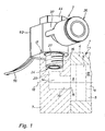
- FIG. 1 shows in dash-dotted lines the end portion of a operated with pneumatic or hydraulic pressure medium fluid power device 1, which is a driven by fluid power drive in the embodiment, For example, a pneumatic working cylinder. It could also be in the fluid power device 1 to another type of device that is operated with fluidic pressure medium, such as a valve or a used for compressed air conditioning maintenance device.
- Trained as a linear drive fluid power device 1 of the embodiment has an elongated device housing 4, which defines a housing interior 5, in which a piston 6 is arranged axially displaceable.
- the housing interior 5 is closed at both ends by a respective housing cover 7, of which, however, only one is shown.
- a connected to the piston 6 piston rod 8 passes through the unillustrated housing cover 7 and allows the connection to a component to be moved (not shown).
- the piston 6 divides the housing interior 5 with sealing in two working chambers 9, 10, with respect to which a fluidic pressure medium can be supplied and discharged to displace the piston 6 in a desired manner linear.
- the device channel 14 opens with an inner mouth 15 in particular coaxially in the associated working chamber 9 and is open with an outer mouth 16 to an outer surface 17 of the device housing 4, in this case on the housing cover 7, open.
- the outer mouth 16 is oriented in the embodiment perpendicular to the longitudinal axis 18 of the fluid power device, whereas the inner mouth 15 in the direction of the longitudinal axis 18 refers, so that the device channel 14 a to 90 ° bent course.
- the device channel 14 in the embodiment has an outgoing from the inner mouth 15 axial longitudinal portion 19 and an outgoing from the outer mouth 16 radial length portion 20th
- This connector 3 has the advantage that it is equipped with a flow detection device 2 directly, which allows a very accurate detection of the flow rate of the flowing through the connector 3 and thus to or from the fluid power device 1 inflowing or outflowing pressure medium. So it is a flow detection device 2 integrated into the connector 3, which therefore has a dual function and with compact dimensions allows both the flow control and the flow detection.
- the connector 3 includes a main body, designated in its entirety by reference number 21, which is equipped with a device connection 24 on the one hand and with a line connection 25 on the other hand. Between the two terminals 24, 25 runs in the interior of the main housing 21 in its entirety designated by reference numeral 26 connecting channel. Through the connecting channel 26 can fluid between the two terminals 24, 25 - in the embodiment in both directions - flow.
- the connector 3 in the mouth region of the outer mouth 16 of the device channel 14 in particular be releasably secured.
- the attachment is done in the embodiment by screwing the device port 24 in the outer orifice 16 and the adjoining channel section.
- the device port 24 is formed for this purpose hollow cylindrical and provided with an external thread 27, which in a complementary internal thread of the device channel 14 can be screwed.
- the device connection 24 is thus a screw connection and can be inserted into the device channel 14 by means of a screwdriving process.
- the device port 24 is formed as a plug-in shaft, wherein the device side in the region of the outer orifice 16 is a plug connection device which allows a fastening of the connector 3 by a plug-in operation.
- the line connection 25 is provided for the particular detachable fastening of a dash-dotted line indicated fluid line 28.
- the fluid line 28 may in particular be a pressure medium hose.
- the line connection 25 can in principle also be designed as a screw connection, in or on which a fluid line 28 can be fastened by a screwing operation. In the embodiment, however, it contains the preferred embodiment of a plug-in connection, in which the fluid line 28 only has to be inserted coaxially for connection. For releasing a release element 29 of the line connection 25 is actuated, so that holding means, not shown, get out of engagement with the wall of the fluid line 28 and the fluid line 28 can be pulled out without destruction.
- the connecting piece 3 is formed in the embodiment as an angle piece.
- the two terminals 24, 25 are at an angle to each other and preferably perpendicular to each other.
- the line connection 25 is placed laterally on the connection piece 3.
- connection channel 26 is divided into a first and a second connection channel section. These two connecting channel sections 32, 33 run in the embodiment at right angles to each other. In addition, the two connecting channel sections 32, 33 are in two separate components housing the main housing 21, wherein the first connection channel section 32 extends in a device housing 24 having the first main housing body 34, while the second connection channel section 33 extends in a equipped with the line connection 25 second main housing body 35.
- the two main housing bodies 34, 35 are coupled together. It may be a fixed connection, but the embodiment provides a rotatable connection, since here the connection piece 3 is formed in the manner of a swivel fitting.
- the second main housing body 35 is designed as a pivoting part, which is rotatably mounted on the elongated, in particular designed as a hollow screw first main housing body 34.
- the pivoting part 36 has a coaxially seated on the first main housing body 34 annular body 37, from which a connecting piece 38 projects radially, at the free end of the line connection 25 is provided.
- the second connecting channel section 33 passes through the connecting piece 38 in the longitudinal direction and meets with perpendicular orientation to the first main housing body 34.
- the first connecting channel section 32 is connected via one or more radial holes 39 with a defined between the first main housing body 34 and the annular body 37 concentric annular channel 42 in connection ,
- the second connecting channel section 33 opens out at the inner surface of the annular body 37 at the level of the annular channel 42. As a result, it is always in fluid communication with the first connection channel section 32, regardless of the instantaneous rotational position of the pivoting part 36.
- the first connecting channel section 32 terminates at the top of the connecting piece 3 opposite the appliance connection 24 within the first main housing body 34.
- a head 44 of the first main housing body 34 adjoins there, the outside surface of which is preferably designed to form a screwing tool for the inlet and outlet Unscrew the first main housing body 34 with respect to the device channel 14 attach.
- the above-mentioned flow rate detecting means 2 is provided with pressure drop generating means 46 which are turned on in the communication passage 26. They are preferably located in the first connecting channel section 32 running in the first main housing body 34. They bring about a pressure drop of the pressure medium flowing through them, so that, relative to the flow direction, a higher pressure prevails in front of them than afterwards.
- the pressure drop generating means 46 are formed by a diaphragm 47, which defines within the connecting channel 26 a narrowing the flow cross-section concentrically narrowing.
- a bypass channel 48 opens into the connection channel 26 at two tapping points 52, 53.
- the tapping points 52, 53 are arranged in the running direction of the connecting channel 26 at a distance from each other, wherein they are provided, at least in connection with a diaphragm 47, on the one hand before and the other after the pressure drop generating means 46.
- a mass flow sensor device 54 which is located outside the connecting channel 26 and is based on a calorimetric operating principle and which is provided on or in the connection piece 3.
- the mass flow sensor device 54 determines the mass flow flowing through the bypass channel 48, which has a relatively small diameter compared to the connection channel 26, which is correlated to the flow in the connection channel 26 in an evaluation electronics 55 also provided on or in the connection piece 3.
- a tap of the desired measured values can take place via electrical cables 56 connected to the evaluation electronics 55 or via other electromechanical connection measures.
- the mass flow sensor device 54 is housed together with the evaluation electronics 55 in a receiving housing 57, which is designed as part of the connecting piece 3. It may be a separate component which is fixed by any fastening means on the main housing 21.
- the receiving housing 57 is partially formed by the main housing 21, which assumes a dual function in this respect.
- the receiving housing 57 defines a receiving space 58 containing the aforementioned components.
- This receiving space 58 can be made accessible by removing a removable housing cover 62 of the receiving housing 57. As a result, the individual components can be easily replaced in the event of a defect.
- the receiving housing 57 is provided on the second main housing body 35. It is expediently located on the line connection 25 with respect to the longitudinal axis 45 diametrically opposite side. Accordingly, the mass flow sensor device 54 is arranged in this area. This allows in the longitudinal direction of the first main housing body 34, ie in the height direction of the connecting piece 3, very compact dimensions.
- the mass flow sensor device 54 is formed as a chip, which is manufactured by known technologies of microsystem technology. It includes an active chip area 63 which is arranged to be contacted by the pressure medium flowing through the bypass channel.
- the mass flow sensor device 54 can not only determine the flow through the bypass channel, but is also able to detect the flow direction.
- the measuring method of the so-called heat transfer anemometry is used. Since the flow direction in the bypass channel corresponds to the instantaneous flow direction in the connection channel 26, the flow rate detection device 2 is therefore also able to detect the flow direction of the pressure medium in the connection channel.
- the connector in addition to the flow detection device 2 also with pressure detection means 64 and / or with temperature detection means 65 for detecting the corresponding Data of the pressure medium prevailing in the connection channel can be equipped.
- the picking up of the measured values preferably takes place via corresponding tap channels 66 directly in the connecting channel 26.
- the active components are expediently, like the active chip surface 63, directly on the optionally present chip.
- the connector 3 of the embodiment is characterized by a high flexibility with regard to the processable measuring range.
- the flow-detecting device 2 can be used without replacement in turn, to measure different volume flows in the connecting channel 26.
- a simple replacement of the pressure drop generating means 46 is sufficient.
- the existing aperture 47 is replaced by a diaphragm with a larger or smaller aperture diameter. It is therefore possible to achieve that, regardless of the volume flow, comparable pressure differences occur at the diaphragm which the mass flow sensor device 54 can easily handle.
- the modularity is realized in that the pressure drop generating means 46 - here: the aperture 47 - part of an insert body 68 which is interchangeable fixed in the main housing 21.
- the insert body 68 is in the embodiment of a sleeve-shaped component with integrally formed aperture 47. It can in a complementary receptacle 69 of the first main housing body 34 are used, wherein it defines with its inner circumference at the same time a longitudinal portion of the first connecting channel section 32.
- a plurality of insert bodies 68 can be provided, which have different cross-sectional geometries and which are alternatively inserted into the receptacle 69, in accordance with the expected flow conditions.
Landscapes
- Engineering & Computer Science (AREA)
- General Engineering & Computer Science (AREA)
- Mechanical Engineering (AREA)
- Physics & Mathematics (AREA)
- Fluid Mechanics (AREA)
- General Physics & Mathematics (AREA)
- Measuring Volume Flow (AREA)
- Rigid Pipes And Flexible Pipes (AREA)
Description
- Die Erfindung betrifft ein als Winkelstück ausgebildetes Anschlussstück zum Anschließen einer Fluidleitung an ein fluidtechnisches Gerät, beispielsweise einen Antrieb, ein Ventil oder ein Wartungsgerät, mit einem Leitungsanschluss zum Fixieren einer Fluidleitung, mit einem rechtwinkelig zu dem Leitungsanschluss orientierten Geräteanschluss zum Befestigen an einem fluidtechnischen Gerät und mit einem in einem Hauptgehäuse zwischen dem Leitungsanschluss und dem Geräteanschluss verlaufenden, das Hindurchströmen eines Fluides ermöglichenden Verbindungskanal, wobei das Hauptgehäuse einen den Geräteanschluss aufweisenden ersten Hauptgehäusekörper mit einem ersten Verbindungskanalabschnitt und einen den Leitungsanschluss aufweisenden zweiten Hauptgehäusekörper mit einem mit dem ersten Verbindungskanalabschnitt kommunizierenden zweiten Verbindungskanalabschnitt aufweist.
- Ein Anschlussstück dieser Art geht beispielsweise aus der
DE 20008129 U hervor. Es ermöglicht den Anschluss einer Fluidleitung an einem mit einem Druckmedium zu versorgenden fluidtechnischen Gerät. Ein beispielsweise als Schraubanschluss ausgebildeter Geräteanschluss ermöglicht das Befestigen des Anschlussstückes am fluidtechnischen Gerät. Ein rechtwinkelig dazu orientierter Leitungsanschluss ermöglicht das insbesondere lösbare Fixieren einer Fluidleitung. Im Betrieb kann Druckmedium, je nach Ausgestaltung des Anschlussstückes, in der einen oder anderen Richtung zwischen den beiden Anschlüssen überströmen, wobei es einen Verbindungskanal des Anschlussstückes durchströmt. - Beim Betrieb fluidtechnischer Geräte ist es von Fall zu Fall erforderlich, die in der Regel nur als "Durchfluss" bezeichnete Durchflussrate an Druckmedium zum und/oder vom betreffenden fluidtechnischen Gerät zu bestimmen. In solchen Fällen ist es bekannt, einen Durchflusssensor in den Verlauf der Fluidleitung einzuschalten, wie er beispielsweise aus der
DE 29821673 U1 oder aus derUS 5332005 hervorgeht. Im Falle derDE 29821673 U1 enthält der Durchflusssensor ein Gehäuse mit axial durchgehendem Kanal, in dem ein federbelasteter Staukörper untergebracht ist. Das zuströmende Druckmedium verlagert den Staukörper, der in Abhängigkeit von seiner Position einen Positionssensor betätigt. Im Falle derUS 5332005 ist ein sogenanntes Laminar-Flow-Element vorgesehen, um einen Druckabfall des hindurchströmenden Mediums hervorzurufen. Ein vor und nach dem Laminar-Flow-Element einmündender Bypass-Kanal ist einer Massenstrom-Sensoreinrichtung zugeordnet, deren Messwerte die Berechnung des Durchflusses bzw. der Durchflussrate gestatten. - Beide bekannten Durchfluss-Messvorrichtungen erfordern eine umständliche Installation im Verlauf einer Fluidleitung. Handelt es sich um eine flexible Fluidleitung, beispielsweise ein Druckluftschlauch, sind überdies zusätzliche Befestigungsmaßnahmen zu treffen, um die Durchfluss-Messvorrichtung an Ort und Stelle sicher zu fixieren.
- Aus der
US-A-5944048 ist eine Vorrichtung zur Detektion und Steuerung des Durchflusses eines Fluides bekannt, die ein Hauptgehäuse mit zwei sich koaxial gegenüberliegenden Anschlüssen aufweist. Eine zur Messung des Durchflusses dienende Massenstrom-Sensoreinrichtung ist an der Oberseite des Hauptgehäuses befestigt und kommuniziert über einen Bypass-Kanal mit einem die beiden Anschlüsse verbindenden Verbindungskanal. Eine Vorrichtung vergleichbaren Aufbaues offenbart auch dieEP-B-0664879 . - Es ist die Aufgabe der vorliegenden Erfindung, Maßnahmen vorzuschlagen, die eine einfache Durchflussmessung ermöglichen.
- Zur Lösung dieser Aufgabe ist bei einem Anschlussstück der eingangs genannten Art vorgesehen, dass das Anschlussstück selbst mit einer Durchfluss-Erfassungseinrichtung ausgestattet ist, die in den Verbindungskanal eingeschaltete Druckabfall-Erzeugungsmittel und einen im Bereich der Druckabfall-Erzeugungsmittel an in Verlaufsrichtung des Verbindungskanals beabstandeten Stellen in den Verbindungskanal einmündenden Bypass-Kanal enthält, wobei dem Bypass-Kanal eine außerhalb des Verbindungskanals platzierte, auf kalorimetrischem Funktionsprinzip basierende Massenstrom-Sensoreinrichtung am oder im Anschlussstück zugeordnet ist, die auf der dem Leitungsanschluss entgegengesetzten Seite angeordnet ist.
- Auf diese Weise ist die Durchfluss-Erfassungseinrichtung als unmittelbarer Bestandteil des Anschlussstückes ausgebildet und erfordert mithin keine gesonderte Herstellung oder Installation. Bei der Installation des Anschlussstückes wird die Durchfluss-Erfassungseinrichtung automatisch mitinstalliert, wobei keine besonderen Befestigungsmaßnahmen erforderlich sind, weil der Geräteanschluss die erforderliche sichere Fixierung liefert. Es besteht die Möglichkeit, die Durchfluss-Erfassungseinrichtung in ein gebräuchliches Standard-Anschlussstück zu integrieren. Insgesamt kann auf extrem reduzierten Platzverhältnissen der aktuelle Durchfluss ermittelt werden. Der Einsatz einer Massenstrom-Sensoreinrichtung lässt sich extrem kompakt realisieren, insbesondere wenn sie mit mikromechanischen Technologien hergestellt wurde. Außerdem kann die Möglichkeit geschaffen werden, über den ermittelten Wärmetransfer strömungsrichtungsabhängig den aktuellen Massenstrom zu bestimmen (Heat-Transfer-Anemometer). Eine besonders niedrige Bauweise ist möglich, weil die Massenstrom-Sensoreinrichtung auf der dem Leitungsanschluss entgegengesetzten Seite platziert ist.
- Vorteilhafte Weiterbildungen der Erfindung gehen aus den Unteransprüchen hervor.
- Die Massenstrom-Sensoreinrichtung ist zweckmäßigerweise geschützt in einem Aufnahmegehäuse untergebracht, das an dem den Verbindungskanal enthaltenden Hauptgehäuse des Anschlussstückes angebracht ist oder gar ganz oder teilweise von diesem Hauptgehäuse gebildet ist. Auf diese Weise lässt sich problemlos eine Schutzart von IP65 oder besser realisieren. Ist das Aufnahmegehäuse mit einem abnehmbaren Deckel versehen, kann bei Bedarf ein Austausch der Massenstrom-Sensoreinrichtung vorgenommen werden, wenn eine Umrüstung auf andere Durchflusswerte erforderlich ist.
- Das Aufnahmegehäuse enthält zweckmäßigerweise auch eine gegebenenfalls vorhandene Auswerteelektronik der Durchfluss-Erfassungseinrichtung.
- Besonders kleine Abmessungen sind möglich, wenn die Massenstrom-Sensoreinrichtung als Chip ausgebildet ist. Er kann mit hoher Präzision durch die Technologien der Mikrosystemtechnik realisiert werden, beispielsweise Abform- und/oder Ätztechniken oder auch mikromechanische Bearbeitungen mittels entsprechend miniaturisierten Werkzeugen.
- In allen Fällen ermöglicht die Durchfluss-Erfassungseinrichtung eine Diagnose des mit dem Anschlussstück ausgestatteten fluidtechnischen Gerätes, wobei die erfassten Werte einer übergeordneten Steuereinrichtung zugeleitet werden können, die ergebnisabhängig gewisse Maßnahmen veranlasst.
- Die Druckabfall-Erzeugungsmittel sind zweckmäßigerweise Bestandteil eine austauschbaren Einsatzkörpers des Anschlussstückes. Insbesondere kann der Einsatzkörper austauschbar im Hauptgehäuse des Anschlussstückes installiert sein. Der dadurch realisierte modulare Aufbau ermöglicht von Fall zu Fall die Verwendung unterschiedlicher Druckabfall-Erzeugungsmittel in Abhängigkeit von den vorhandenen Durchflusswerten. Um für unterschiedliche Strömungraten vergleichbare Druckdifferenzwerte zu erhalten, die für die Strömung durch den Bypass-Kanal verantwortlich sind, können somit baukastenartig unterschiedliche Druckabfall-Erzeugungsmittel eingesetzt werden, ohne einen Austausch der Massenstrom-Sensoreinrichtung vornehmen zu müssen. Man kann also die elektronischen Komponenten beibehalten und hat nur den rein mechanischen Teil auszutauschen.
- Die Druckabfall-Erzeugungsmittel sind zweckmäßigerweise von einer Blende gebildet. Dadurch wird ein bidirektionales Messen begünstigt. Die Strömung im Bypass-Kanal wird dabei zweckmäßigerweise durch eine geeignete Blendengeometrie mit Eckdruckentnahme erzeugt, wobei der Bypass-Kanal in den beiden Eckbereichen zwischen der Blende und den sich beidseits daran anschließenden Kanalabschnitten in den Verbindungskanal mündet.
- Es ist ferner vorteilhaft, wenn die Durchflussmessung im Anschlussstück zusätzlich mit einer Druck- und/oder Temperaturmessung kombiniert wird. Auf diese Weise können die wesentlichen Parameter der Strömung erfasst und weiterführende Diagnosemaßnahmen betrieben werden.
- Nachfolgend wird die Erfindung anhand der beiliegenden Zeichnung näher erläutert. In dieser zeigen:
- Figur 1
- eine fluidtechnische Anordnung mit einem Endabschnitt eines nur strichpunktiert angedeuteten fluidtechnischen Gerätes, das mit einer bevorzugten Bauform des erfindungsgemäßen Anschlussstückes ausgestattet ist,
- Figur 2
- das Anschlussstück aus
Figur 1 , aus einer anderen Blickrichtung gesehen und - Figur 3
- einen Längsschnitt durch das Anschlussstück der Figuren 1 und 2, wobei strichpunktiert eine angeschlossene oder anschließbare Fluidleitung angedeutet ist.
- Die
Figur 1 zeigt in strichpunktierten Linien den Endabschnitt eines mit pneumatischem oder hydraulischem Druckmedium betriebenen fluidtechnischen Gerätes 1, das beim Ausführungsbeispiel ein durch Fluidkraft betätigter Antrieb ist, beispielweise ein pneumatischer Arbeitszylinder. Es könnte sich bei dem fluidtechnischen Gerät 1 auch um einen anderen Gerätetyp handeln, der mit fluidischem Druckmedium betrieben wird, beispielsweise ein Ventil oder ein zur Druckluftaufbereitung eingesetztes Wartungsgerät. - Das als Linearantrieb ausgebildete fluidtechnische Gerät 1 des Ausführungsbeispiels verfügt über ein längliches Gerätegehäuse 4, das einen Gehäuse-Innenraum 5 definiert, in dem ein Kolben 6 axial verschiebbar angeordnet ist. Der Gehäuse-Innenraum 5 ist an beiden Stirnseiten durch je einen Gehäusedeckel 7 verschlossen, von denen jedoch nur einer abgebildet ist. Eine mit dem Kolben 6 verbundene Kolbenstange 8 durchsetzt den nicht abgebildeten Gehäusedeckel 7 und ermöglicht die Verbindung zu einem zu bewegenden Bauteil (nicht dargestellt).
- Der Kolben 6 unterteilt den Gehäuse-Innenraum 5 unter Abdichtung in zwei Arbeitskammern 9, 10, bezüglich denen ein fluidisches Druckmedium zugeführt und abgeführt werden kann, um den Kolben 6 in einer gewünschten Weise linear zu verlagern. Die Zufuhr und Abfuhr von Druckmedium bezüglich der kolbenstangenseitigen Arbeitskammer 10 erfolgt über einen Gerätekanal im Innern des nicht dargestellten Gehäusedeckels. Die Zufuhr und Abfuhr des Druckmediums bezüglich der auf der entgegengesetzten Seite des Kolbens 6 liegenden Arbeitskammer 9 erfolgt durch einen Gerätekanal 14 hindurch, der das Gerätegehäuse 4 durchsetzt und insbesondere im Gehäusedeckel 7 verläuft. Der Gerätekanal 14 mündet mit einer inneren Mündung 15 insbesondere koaxial in die zugeordnete Arbeitskammer 9 und ist mit einer äußeren Mündung 16 zu einer Außenfläche 17 des Gerätegehäuses 4 hin, vorliegend am Gehäusedeckel 7, offen.
- Die äußere Mündung 16 ist beim Ausführungsbeispiel rechtwinkelig zur Längsachse 18 des fluidtechnischen Gerätes orientiert, wohingegen die innere Mündung 15 in Richtung der Längsachse 18 verweist, so dass der Gerätekanal 14 einen um 90° abknickenden Verlauf hat. Im Einzelnen besitzt der Gerätekanal 14 beim Ausführungsbeispiel einen von der inneren Mündung 15 ausgehenden axialen Längenabschnitt 19 sowie einen von der äußeren Mündung 16 ausgehenden radialen Längenabschnitt 20.
- Die Zufuhr und Abfuhr des Druckmediums erfolgt mittels eines Anschlussstückes 3 der erfindungsgemäßen Bauart. Dieses Anschlussstück 3 hat den Vorteil, dass es unmittelbar mit einer Durchfluss-Erfassungseinrichtung 2 ausgestattet ist, die eine sehr exakte Erfassung der Durchflussrate des durch das Anschlussstück 3 hindurchströmenden und somit zum oder vom fluidtechnischen Gerät 1 zu- bzw. abströmenden Druckmediums ermöglicht. Es ist also eine Durchfluss-Erfassungseinrichtung 2 in das Anschlussstück 3 integriert, das mithin eine Doppelfunktion hat und mit kompakten Abmessungen sowohl die Strömungsführung als auch die Durchflusserfassung ermöglicht.
- Wie insbesondere auch aus
Figur 3 näher hervorgeht, enthält das Anschlussstück 3 ein in seiner Gesamtheit mit Bezugsziffer 21 bezeichnetes Hauptgehäuse, das zum einen mit einem Geräteanschluss 24 und zum anderen mit einem Leitungsanschluss 25 ausgestattet ist. Zwischen den beiden Anschlüssen 24, 25 verläuft im Innern des Hauptgehäuses 21 ein in seiner Gesamtheit mit Bezugsziffer 26 bezeichneter Verbindungskanal. Durch den Verbindungskanal 26 hindurch kann Fluid zwischen den beiden Anschlüssen 24, 25 - beim Ausführungsbeispiel in beiden Richtungen - strömen. - Mit dem Geräteanschluss 24 kann das Anschlussstück 3 im Mündungsbereich der äußeren Mündung 16 des Gerätekanals 14 insbesondere lösbar befestigt werden. Die Befestigung geschieht beim Ausführungsbeispiel durch Einschrauben des Geräteanschlusses 24 in die äußere Mündung 16 und den sich daran anschließenden Kanalabschnitt. Der Geräteanschluss 24 ist zu diesem Zweck hohlzylindrisch ausgebildet und mit einem Außengewinde 27 versehen, das in ein komplementäres Innengewinde des Gerätekanals 14 einschraubbar ist. Der Geräteanschluss 24 ist also ein Schraubanschluss und kann durch einen Schraubvorgang in den Gerätekanal 14 eingesetzt werden.
- Bei einer nicht näher dargestellten alternativen Bauform ist der Geräteanschluss 24 als Steckschaft ausgebildet, wobei sich geräteseitig im Bereich der äußeren Mündung 16 eine Steckverbindungseinrichtung befindet, die ein Befestigen des Anschlussstückes 3 durch einen Steckvorgang ermöglicht.
- Der Leitungsanschluss 25 ist zum insbesondere lösbaren Befestigen einer strichpunktiert angedeuteten Fluidleitung 28 vorgesehen. Die Fluidleitung 28 kann insbesondere ein Druckmittelschlauch sein.
- Der Leitungsanschluss 25 kann prinzipiell ebenfalls als Schraubanschluss ausgeführt sein, in oder an dem sich eine Fluidleitung 28 durch einen Schraubvorgang befestigen lässt. Beim Ausführungsbeispiel enthält er jedoch die bevorzugte Ausgestaltung eines Steckanschlusses, bei dem die Fluidleitung 28 zum Anschließen lediglich koaxial eingesteckt werden muss. Zum Lösen wird ein Löseelement 29 des Leitungsanschlusses 25 betätigt, so dass nicht gezeigte Haltemittel außer Eingriff mit der Wandung der Fluidleitung 28 gelangen und die Fluidleitung 28 zerstörungsfrei herausgezogen werden kann.
- Das Anschlussstück 3 ist beim Ausführungsbeispiel als Winkelstück ausgebildet. Die beiden Anschlüsse 24, 25 sind winkelig zueinander und vorzugsweise rechtwinkelig zueinander angeordnet. Der Leitungsanschluss 25 ist seitlich an dem Anschlussstück 3 platziert.
- Der Verbindungskanal 26 ist in einen ersten und einen zweiten Verbindungskanalabschnitt unterteilt. Diese beiden Verbindungskanalabschnitte 32, 33 verlaufen beim Ausführungsbeispiel rechtwinkelig zueinander. Außerdem sind die beiden Verbindungskanalabschnitte 32, 33 in zwei gesonderten Komponenten des Hauptgehäuses 21 untergebracht, wobei der erste Verbindungskanalabschnitt 32 in einem den Geräteanschluss 24 aufweisenden ersten Hauptgehäusekörper 34 verläuft, während sich der zweite Verbindungskanalabschnitt 33 in einem mit dem Leitungsanschluss 25 ausgestatteten zweiten Hauptgehäusekörper 35 erstreckt.
- Die beiden Hauptgehäusekörper 34, 35 sind miteinander gekoppelt. Es kann sich um eine feste Verbindung handeln, wobei das Ausführungsbeispiel jedoch eine drehbewegliche Verbindung vorsieht, da hier das Anschlussstück 3 nach Art einer Schwenkverschraubung ausgebildet ist.
- Der zweite Hauptgehäusekörper 35 ist als Schwenkteil ausgebildet, das verdrehbar auf dem länglichen, insbesondere als Hohlschraube ausgebildeten ersten Hauptgehäusekörper 34 gelagert ist. Zur Drehlagerung verfügt das Schwenkteil 36 über einen koaxial auf dem ersten Hauptgehäusekörper 34 sitzenden Ringkörper 37, von dem ein Anschlussstutzen 38 radial absteht, an dessen freiem Ende der Leitungsanschluss 25 vorgesehen ist.
- Der zweite Verbindungskanalabschnitt 33 durchsetzt den Anschlussstutzen 38 in Längsrichtung und trifft mit rechtwinkeliger Ausrichtung auf den ersten Hauptgehäusekörper 34. Der erste Verbindungskanalabschnitt 32 steht über eine oder mehrere radiale Bohrungen 39 mit einem zwischen dem ersten Hauptgehäusekörper 34 und dem Ringkörper 37 definierten konzentrischen Ringkanal 42 in Verbindung. Der zweite Verbindungskanalabschnitt 33 mündet an der Innenfläche des Ringkörpers 37 auf Höhe des Ringkanals 42 aus. Dadurch steht er unabhängig von der momentanen Drehposition des Schwenkteils 36 stets mit dem ersten Verbindungskanalabschnitt 32 in fluidischer Verbindung.
- Zwei axial beabstandete Ringdichtungen 43 zwischen den beiden Hauptgehäusekörpern 34, 35 sorgen für einen leckagefreien Fluidübertritt zwischen den beiden Verbindungskanaläbschnitten 32, 33.
- Der erste Verbindungskanalabschnitt 32 endet an der dem Geräteanschluss 24 entgegengesetzten Oberseite des Anschlussstückes 3 innerhalb des ersten Hauptgehäusekörpers 34. Es schließt sich dort ein Kopf 44 des ersten Hauptgehäusekörpers 34 an, dessen Außenfläche vorzugsweise so gestaltet ist, dass sich ein Schraubwerkzeug für das Ein- und Ausschrauben des ersten Hauptgehäusekörpers 34 bezüglich des Gerätekanals 14 ansetzen lässt.
- Die oben angesprochene Durchfluss-Erfassungseinrichtung 2 ist mit Druckabfall-Erzeugungsmitteln 46 ausgestattet, die in den Verbindungskanal 26 eingeschaltet sind. Bevorzugt befinden sie sich in dem im ersten Hauptgehäusekörper 34 verlaufenden ersten Verbindungskanalabschnitt 32. Sie bewirken einen Druckabfall des durch sie hindurchströmenden Druckmediums, so dass, bezogen auf die Strömungsrichtung, vor ihnen ein höherer Druck herrscht als danach. Bevorzugt sind die Druckabfall-Erzeugungsmittel 46 von einer Blende 47 gebildet, die innerhalb des Verbindungskanals 26 eine den Strömungsquerschnitt konzentrisch verengende Engstelle definiert.
- Im Bereich der Druckabfall-Erzeugungsmittel 46 mündet ein Bypass-Kanal 48 an zwei Abgriffsstellen 52, 53 in den Verbindungskanal 26 ein. Die Abgriffsstellen 52, 53 sind in der Verlaufsrichtung des Verbindungskanals 26 mit Abstand zueinander angeordnet, wobei sie, zumindest im Zusammenhang mit einer Blende 47, zum einen vor und zum anderen nach den Druckabfall-Erzeugungsmitteln 46 vorgesehen sind.
- Wenn im Betrieb des Anschlussstückes Druckmedium durch den Verbindungskanal 26 strömt, stellt sich im Verbindungskanal 26 eine Druckdifferenz zwischen den beiden durch die Blende 47 voneinander getrennten Kanalabschnitten ein. Diese Druckdifferenz führt dazu, dass ein Teil des Druckmediums die Blende 47 durch den Bypass-Kanal 48 hindurch umströmt. Die Abgriffsstellen 52, 53 befinden sich hier zweckmäßigerweise in den beiden Eckbereichen zwischen der Blende 47 und den sich beidseits daran anschließenden Kanalabschnitten des Verbindungskanals 26, so dass man von einer Eckdruckentnahme sprechen kann.
- Dem Bypass-Kanal 48 ist eine außerhalb des Verbindungskanals 26 platzierte, auf kalorimetrischem Funktionsprinzip basierende Massenstrom-Sensoreinrichtung 54 zugeordnet, die am oder im Anschlussstück 3 vorgesehen ist. Die Massenstrom-Sensoreinrichtung 54 ermittelt den durch den im Vergleich zum Verbindungskanal 26 einen relativ kleinen Durchmesser aufweisenden Bypass-Kanal 48 strömenden Massenstrom, der in einer ebenfalls am oder im Anschlussstück 3 vorgesehenen Auswerteelektronik 55 zur Strömung im Verbindungskanal 26 korreliert wird. Somit kann letztlich über mit der Auswerteelektronik 55 verbundene elektrische Kabel 56 oder über andere elektromechanische Anschlussmaßnahmen ein Abgriff der gewünschten Messwerte erfolgen.
- Die Massenstrom-Sensoreinrichtung 54 ist zusammen mit der Auswerteelektronik 55 in einem Aufnahmegehäuse 57 untergebracht, das als Bestandteil des Anschlussstückes 3 ausgeführt ist. Es kann sich um eine gesonderte Komponente handeln, die durch beliebige Befestigungsmittel am Hauptgehäuse 21 fixiert ist. Beim Ausführungsbeispiel ist das Aufnahmegehäuse 57 teilweise vom Hauptgehäuse 21 gebildet, das insoweit eine Doppelfunktion übernimmt.
- Das Aufnahmegehäuse 57 definiert einen Aufnahmeraum 58, der die vorerwähnten Komponenten enthält. Dieser Aufnahmeraum 58 kann durch Entfernen eines abnehmbaren Gehäusedeckels 62 des Aufnahmegehäuses 57 zugänglich gemacht werden. Dadurch können die einzelnen Komponenten im Defektfalle leicht ausgetauscht werden.
- Zweckmäßigerweise ist das Aufnahmegehäuse 57 am zweiten Hauptgehäusekörper 35 vorgesehen. Es befindet sich zweckmäßigerweise auf der dem Leitungsanschluss 25 bezüglich der Längsachse 45 diametral entgegengesetzten Seite. Dementsprechend ist auch die Massenstrom-Sensoreinrichtung 54 in diesem Bereich angeordnet. Dies ermöglicht in der Längsrichtung des ersten Hauptgehäusekörpers 34, also in Höhenrichtung des Anschlussstückes 3, sehr kompakte Abmessungen.
- Als weitere Maßnahme, die sehr kompakte Abmessungen ermöglicht, ist die Massenstrom-Sensoreinrichtung 54 als Chip ausgebildet, der durch bekannte Technologien der Mikrosystemtechnik hergestellt ist. Er enthält eine aktive Chipfläche 63, die so angeordnet ist, dass sie von dem den Bypass-Kanal durchströmenden Druckmedium berührt wird.
- Die Massenstrom-Sensoreinrichtung 54 kann nicht nur den Durchfluss durch den Bypass-Kanal bestimmen, sondern ist auch in der Lage, die Strömungsrichtung zu detektieren. Dabei wird das Messverfahren der sogenannten Heat-Transfer-Anemometrie angewandt. Da die Strömungsrichtung im Bypass-Kanal der momentanen Strömungsrichtung im Verbindungskanal 26 entspricht, ist die Durchfluss-Erfassungseinrichtung 2 folglich auch in der Lage, die Strömungsrichtung des Druckmediums im Verbindungskanal zu detektieren.
- Lediglich strichpunktiert ist in
Figur 3 angedeutet, dass das Anschlussstück zusätzlich zu der Durchfluss-Erfassungseinrichtung 2 auch noch mit Druckerfassungsmitteln 64 und/oder mit Temperaturerfassungsmitteln 65 zur Erfassung der entsprechenden Daten des im Verbindungskanal herrschenden Druckmediums ausgestattet sein kann. Der Abgriff der Messwerte erfolgt vorzugsweise über entsprechende Abgriffskanäle 66 unmittelbar im Verbindungskanal 26. Die aktiven Bestandteile befinden sich zweckmäßigerweise, wie die aktive Chipfläche 63, direkt an dem gegebenenfalls vorhandenen Chip. - Damit die Drehbarkeit des Schwenkteils 36 gegeben ist, sind die zu den beiden Abgriffsstellen 52, 53 führenden Kanaläste des Bypass-Kanals in vergleichbarer Weise in zwei Kanalabschnitte unterteilt, wie dies beim Verbindungskanal 26 der Fall ist. Zwischen den beiden Kanalabschnitten erstreckt sich jeweils ein Ringkanal 67, der zwischen dem Ringkörper 37 und dem ersten Hauptgehäusekörper 34 vorgesehen ist und der eine Fluidverbindung unabhängig von der jeweiligen Drehposition des Schwenkteils 36 garantiert.
- Das Anschlussstück 3 des Ausführungsbeispiels zeichnet sich durch eine hohe Flexibilität hinsichtlich des verarbeitbaren Messbereiches aus. Die Durchfluss-Erfassungseinrichtung 2 kann ohne Austausch ihrerseits eingesetzt werden, um unterschiedlich große Volumenströme im Verbindungskanal 26 zu messen. In diesem Falle genügt ein einfacher Austausch der Druckabfall-Erzeugungsmittel 46. Beim Ausführungsbeispiel wird hierzu die vorhandene Blende 47 durch eine Blende mit größerem oder kleinerem Blendendurchmesser ausgetauscht. Man kann somit erreichen, dass unabhängig vom Volumenstrom vergleichbare Druckdifferenzen an der Blende auftreten, die die Massenstrom-Sensoreinrichtung 54 bequem verarbeiten kann.
- Beim Ausführungsbeispiel wird die Modularität dadurch realisiert, dass die Druckabfall-Erzeugungsmittel 46 - hier: die Blende 47 - Bestandteil eines Einsatzkörpers 68 sind, der austauschbar im Hauptgehäuse 21 fixiert ist.
- Der Einsatzkörper 68 ist beim Ausführungsbeispiel ein hülsenförmiges Bauteil mit angeformter Blende 47. Es kann in eine komplementäre Aufnahme 69 des ersten Hauptgehäusekörpers 34 eingesetzt werden, wobei es mit seinem Innenumfang gleichzeitig einen Längenabschnitt des ersten Verbindungskanalabschnittes 32 definiert.
- Bei der Herstellung oder beim späteren Einsatz des Anschlussstückes 3 können mehrere Einsatzkörper 68 bereitgestellt werden, die über unterschiedliche Querschnittsgeometrien verfügen und die alternativ in die Aufnahme 69 eingesetzt werden, entsprechend den zu erwartenden Strömungsverhältnissen.
Claims (16)
- Als Winkelstück ausgebildetes Anschlussstück zum Anschließen einer Fluidleitung an ein fluidtechnisches Gerät, beispielsweise einen Antrieb, ein Ventil oder ein Wartungsgerät, mit einem Leitungsanschluss (25) zum Fixieren einer Fluidleitung (28), mit einem rechtwinkelig zu dem Leitungsanschluss (25) orientierten Geräteanschluss (24) zum Befestigen an einem fluidtechnischen Gerät (1) und mit einem in einem Hauptgehäuse (21) zwischen dem Leitungsanschluss (25) und dem Geräteanschluss (24) verlaufenden, das Hindurchströmen eines Fluides ermöglichenden Verbindungskanal (26), wobei das Hauptgehäuse (21) einen den Geräteanschluss (24) aufweisenden ersten Hauptgehäusekörper (34) mit einem ersten Verbindungskanalabschnitt (32) und einen den Leitungsanschluss (25) aufweisenden zweiten Hauptgehäusekörper (35) mit einem mit dem ersten Verbindungskanalabschnitt (32) kommunizierenden zweiten Verbindungskanalabschnitt (33) aufweist, dadurch gekennzeichnet, dass das Anschlussstück (3) selbst mit einer Durchfluss-Erfassungseinrichtung (2) ausgestattet ist, die in den Verbindungskanal (26) eingeschaltete Druckabfall-Erzeugungsmittel (46) und einen im Bereich der Druckabfall-Erzeugungsmittel (46) an in Verlaufsrichtung des Verbindungskanals (26) beabstandeten Stellen in den Verbindungskanal (26) einmündenden Bypass-Kanal (48) enthält, wobei dem Bypass-Kanal (48) eine außerhalb des Verbindungskanals (26) platzierte, auf kalorimetrischem Funktionsprinzip basierende Massenstrom-Sensoreinrichtung (54) am oder im Anschlussstück (3) zugeordnet ist, die auf der dem Leitungsanschluss (25) entgegengesetzten Seite angeordnet ist.
- Anschlussstück nach Anspruch 1, dadurch gekennzeichnet, dass der zweite Hauptgehäusekörper (35) als an dem ersten Hauptgehäusekörper (34) drehbar gelagertes Schwenkteil (36) ausgebildet ist.
- Anschlussstück nach Anspruch 1 oder 2, dadurch gekennzeichnet, dass die Massenstrom-Sensoreinrichtung (54) in einem an dem Hauptgehäuse (21) angeordneten oder zumindest teilweise von dem Hauptgehäuse (21) gebildeten Aufnahmegehäuse (57) untergebracht ist.
- Anschlussstück nach Anspruch 3, gekennzeichnet durch einen abnehmbaren Deckel (62) des Aufnahmegehäuses (57).
- Anschlussstück nach einem der Ansprüche 1 bis 4, dadurch gekennzeichnet, dass die Durchfluss-Erfassungseinrichtung (2) eine mit der Massenstrom-Sensoreinrichtung (54) zusammenarbeitende Auswerteelektronik (55) aufweist.
- Anschlussstück nach Anspruch 5 in Verbindung mit Anspruch 3 oder 4, dadurch gekennzeichnet, dass die Auswerteelektronik (55) ebenfalls in dem Aufnahmegehäuse (57) untergebracht ist.
- Anschlussstück nach einem der Ansprüche 3 bis 6, dadurch gekennzeichnet, dass das Aufnahmegehäuse (57) an dem zweiten Hauptgehäusekörper (35) vorgesehen ist.
- Anschlussstück nach einem der Ansprüche 1 bis 7, dadurch gekennzeichnet, dass die Massenstrom-Sensoreinrichtung (54) als Chip ausgebildet ist.
- Anschlussstück nach einem der Ansprüche 1 bis 8, dadurch gekennzeichnet, dass die Massenstrom-Sensoreinrichtung (54) eine mikrosystemtechnisch aufgebaute Komponente ist.
- Anschlussstück nach einem der Ansprüche 1 bis 9, dadurch gekennzeichnet, dass die Druckabfall-Erzeugungsmittel (46) austauschbar sind.
- Anschlussstück nach Anspruch 10, dadurch gekennzeichnet, dass die Druckabfall-Erzeugungsmittel (46) Bestandteil eines austauschbaren Einsatzkörpers (68) sind.
- Anschlussstück nach Anspruch 11, dadurch gekennzeichnet, dass der Einsatzkörper (68) zumindest einen Längenabschnitt des Verbindungskanals (26) definiert.
- Anschlussstück nach einem der Ansprüche 1 bis 12, dadurch gekennzeichnet, dass die Druckabfall-Erzeugungsmittel (46) von einer Blende (47) gebildet sind.
- Anschlussstück nach Anspruch 13, dadurch gekennzeichnet, dass der Bypass-Kanal (48) in den beiden Eckbereichen zwischen der Blende (47) und den sich beidseits daran anschließenden Abschnitten des Verbindungskanals (26) in den Verbindungskanal (26) mündet.
- Anschlussstück nach einem der Ansprüche 1 bis 14, gekennzeichnet durch eine Ausstattung mit zusätzlichen Druckerfassungsmitteln (64) für den im Verbindungskanal (26) herrschenden Fluiddruck.
- Anschlussstück nach einem der Ansprüche 1 bis 15, gekennzeichnet durch eine Ausstattung mit zusätzlichen Temperaturerfassungsmitteln (65) für die im Verbindungskanal (26) herrschende Fluidtemperatur.
Applications Claiming Priority (3)
| Application Number | Priority Date | Filing Date | Title |
|---|---|---|---|
| DE10259395 | 2002-12-19 | ||
| DE10259395A DE10259395A1 (de) | 2002-12-19 | 2002-12-19 | Anschlussstück für Fluidleitungen |
| PCT/EP2003/014268 WO2004057280A1 (de) | 2002-12-19 | 2003-12-16 | Anschlussstück für fluidleitungen |
Publications (2)
| Publication Number | Publication Date |
|---|---|
| EP1573277A1 EP1573277A1 (de) | 2005-09-14 |
| EP1573277B1 true EP1573277B1 (de) | 2008-03-05 |
Family
ID=32519105
Family Applications (1)
| Application Number | Title | Priority Date | Filing Date |
|---|---|---|---|
| EP03795896A Expired - Lifetime EP1573277B1 (de) | 2002-12-19 | 2003-12-16 | Anschlussstück für fluidleitungen |
Country Status (5)
| Country | Link |
|---|---|
| US (1) | US7213472B2 (de) |
| EP (1) | EP1573277B1 (de) |
| AT (1) | ATE388390T1 (de) |
| DE (2) | DE10259395A1 (de) |
| WO (1) | WO2004057280A1 (de) |
Families Citing this family (9)
| Publication number | Priority date | Publication date | Assignee | Title |
|---|---|---|---|---|
| DE102004046547A1 (de) * | 2004-09-20 | 2006-04-06 | Festo Ag & Co. | Fluidtechnisches Gerät mit Druckregler |
| DE102005038459A1 (de) * | 2005-08-13 | 2007-02-22 | Ott-Jakob Gmbh & Co. Spanntechnik Kg | Drehdurchführung mit Leckagesensor |
| EP2416743B1 (de) * | 2009-04-10 | 2016-03-30 | Tecres S.P.A. | Chirurgische vorrichtung zur injektion von zement in eine knochenhöhle |
| CN102167079A (zh) * | 2011-03-26 | 2011-08-31 | 长治液压有限公司 | 可旋转方向的液压转向泵出油口装置 |
| CA2865495C (en) | 2012-02-28 | 2019-06-11 | Norma U.S. Holding Llc | Automotive selective catalytic reduction (scr) system sensor holder and assembly |
| WO2016027190A1 (en) | 2014-08-20 | 2016-02-25 | Tecres S.P.A. | Device for supplying fluid substances in the body of a patient |
| US10844975B2 (en) * | 2016-06-06 | 2020-11-24 | Parker-Hannifin Corporation | Slide through fitting |
| TWI639790B (zh) * | 2017-01-24 | 2018-11-01 | 中大冷凍材料股份有限公司 | 接頭的結構 |
| CN120576833B (zh) * | 2025-08-05 | 2025-11-11 | 祎智量芯(江苏)电子科技有限公司 | 一种基于mems传感器的燃气计量装置 |
Family Cites Families (17)
| Publication number | Priority date | Publication date | Assignee | Title |
|---|---|---|---|---|
| DE7230533U (de) * | 1972-11-16 | Festo Maschinenfab Stoll G | Anschlussverbindungsstück für Leitungen für gasförmige Medien | |
| US2845282A (en) * | 1950-09-09 | 1958-07-29 | Mueller Otto | Pipe connector having adjustable elbow |
| DE1773337B1 (de) * | 1968-05-02 | 1971-04-22 | Linde Ag | Vorrichtung zur entnahme der druecke fuer eine different druck messeinrichtung fuer fluessigkeiten z b mit druckent nahmestellen beiderseits einer messblende |
| IT992634B (it) | 1972-08-18 | 1975-09-30 | Festo Maschf Stoll G | Elemento di raccordo per il collegamento di condotte per mezzi gassosi |
| US4083245A (en) * | 1977-03-21 | 1978-04-11 | Research Development Corporation | Variable orifice gas flow sensing head |
| DE3905524A1 (de) * | 1989-02-23 | 1990-08-30 | Weber Guenther | Elementanordnung fuer kalorimetrische stroemungssensoren |
| EP0664879B1 (de) | 1992-10-16 | 2000-01-05 | Unit Instruments, Inc. | Thermischer massendurchflussregler mit senkrecht angeordnetem massendurchflusssensor |
| US5332005A (en) * | 1992-11-06 | 1994-07-26 | Aalborg Instruments & Controls, Inc. | Laminar flow element and method for metering fluid flow |
| JP3431631B2 (ja) * | 1993-10-06 | 2003-07-28 | ユニット インストルメンツ インコーポレーテッド | プロセス流体の処理装置 |
| US6058787A (en) * | 1996-06-21 | 2000-05-09 | Hughes Technology Group L.L.C | Mass flow measuring device |
| US5944048A (en) * | 1996-10-04 | 1999-08-31 | Emerson Electric Co. | Method and apparatus for detecting and controlling mass flow |
| FR2766568B1 (fr) * | 1997-07-23 | 1999-09-10 | Saime Sarl | Capteur de debit de gaz et appareil d'assistance respiratoire comportant un tel capteur |
| US5861546A (en) * | 1997-08-20 | 1999-01-19 | Sagi; Nehemiah Hemi | Intelligent gas flow measurement and leak detection apparatus |
| US6128963A (en) * | 1998-05-28 | 2000-10-10 | Instrumentarium Corp. | Gas flow restricting and sensing device |
| DE29821673U1 (de) * | 1998-12-04 | 2000-04-13 | Zucht, Manfred, 82275 Emmering | Fluidtechnische Einrichtung, insbesondere Durchflußsensor mit Gehäuse aus Leitungsverbindungselementen |
| US6578435B2 (en) * | 1999-11-23 | 2003-06-17 | Nt International, Inc. | Chemically inert flow control with non-contaminating body |
| DE20008129U1 (de) | 2000-05-05 | 2000-08-10 | Festo AG & Co, 73734 Esslingen | Anschlußteil für Fluidleitungen |
-
2002
- 2002-12-19 DE DE10259395A patent/DE10259395A1/de not_active Withdrawn
-
2003
- 2003-12-16 EP EP03795896A patent/EP1573277B1/de not_active Expired - Lifetime
- 2003-12-16 DE DE50309344T patent/DE50309344D1/de not_active Expired - Lifetime
- 2003-12-16 WO PCT/EP2003/014268 patent/WO2004057280A1/de not_active Ceased
- 2003-12-16 US US10/529,320 patent/US7213472B2/en not_active Expired - Fee Related
- 2003-12-16 AT AT03795896T patent/ATE388390T1/de not_active IP Right Cessation
Also Published As
| Publication number | Publication date |
|---|---|
| DE10259395A1 (de) | 2004-07-22 |
| US7213472B2 (en) | 2007-05-08 |
| WO2004057280A1 (de) | 2004-07-08 |
| ATE388390T1 (de) | 2008-03-15 |
| DE50309344D1 (de) | 2008-04-17 |
| EP1573277A1 (de) | 2005-09-14 |
| US20060150729A1 (en) | 2006-07-13 |
Similar Documents
| Publication | Publication Date | Title |
|---|---|---|
| EP2427275B1 (de) | Spritzpistole mit abnehmbarer druckmesseinrichtung | |
| EP1984631B1 (de) | Modulares druckluft -wartungsgerät | |
| DE10247869B4 (de) | Druckmediumsbetätigter Arbeitszylinder | |
| DE29811901U1 (de) | Kniehebelspannvorrichtung oder Kolben-Zylinder-Einheit | |
| EP1573277B1 (de) | Anschlussstück für fluidleitungen | |
| DE3638604A1 (de) | Fluidisches system mit volumenstrommesseinrichtung | |
| WO1999050584A1 (de) | Vorrichtung zum nachträglichen einbau eines fluidzählers in eine rohrleitung | |
| EP1694967B1 (de) | Gebläse mit Laminar-flow-element vor der Ansaugöffnung | |
| DE19600286C2 (de) | Kompaktregelventil | |
| DE102006022981B4 (de) | Sondeneinrichtung zur Messung von Prozessgrößen | |
| DE102012016041B4 (de) | Filtergerät zum Filtern von Druckluft | |
| EP1464842B1 (de) | Vakuumerzeugervorrichtung | |
| DE102016215156A1 (de) | Fluidsteuergerät | |
| EP2241864B1 (de) | Vorrichtung zur Messung des Volumens- oder Messestromes eines Mediums mittels Differenzdrucksensors mit einer Verbindungsvorrichtung für den Sensor | |
| EP1030289A2 (de) | Sensorhaltevorrichtung | |
| DE102008064455A1 (de) | Überwachungsvorrichtung zur Überwachung eines fließfähigen Mediums | |
| DE4007279C2 (de) | Anschlußvorrichtung für Einstutzen-Gaszähler | |
| DE202005018866U1 (de) | Druck- und Durchflussmessvorrichtung | |
| EP4066728B1 (de) | Fluidverteiler für eine aufbereitungseinrichtung zum aufbereiten von chirurgischen instrumenten | |
| DE20217571U1 (de) | Sensor zur Erfassung von Differenzdrücken | |
| EP2076702A1 (de) | Durchflusseinstellventil | |
| DE102008064412A1 (de) | Gehäusekörper für eine Flusssteuer-oder -Überwachungsvorrichtung | |
| WO2018073270A1 (de) | Steigrohranordnung zur erfassung eines pegels einer metallschmelze | |
| DE20305733U1 (de) | Vakuumerzeugervorrichtung | |
| EP0299195A2 (de) | Vorrichtung zum Messen und Regeln eines Gasmassenflusses |
Legal Events
| Date | Code | Title | Description |
|---|---|---|---|
| PUAI | Public reference made under article 153(3) epc to a published international application that has entered the european phase |
Free format text: ORIGINAL CODE: 0009012 |
|
| 17P | Request for examination filed |
Effective date: 20050415 |
|
| AK | Designated contracting states |
Kind code of ref document: A1 Designated state(s): AT BE BG CH CY CZ DE DK EE ES FI FR GB GR HU IE IT LI LU MC NL PT RO SE SI SK TR |
|
| AX | Request for extension of the european patent |
Extension state: AL LT LV MK |
|
| DAX | Request for extension of the european patent (deleted) | ||
| GRAP | Despatch of communication of intention to grant a patent |
Free format text: ORIGINAL CODE: EPIDOSNIGR1 |
|
| GRAS | Grant fee paid |
Free format text: ORIGINAL CODE: EPIDOSNIGR3 |
|
| GRAA | (expected) grant |
Free format text: ORIGINAL CODE: 0009210 |
|
| AK | Designated contracting states |
Kind code of ref document: B1 Designated state(s): AT BE BG CH CY CZ DE DK EE ES FI FR GB GR HU IE IT LI LU MC NL PT RO SE SI SK TR |
|
| REG | Reference to a national code |
Ref country code: GB Ref legal event code: FG4D Free format text: NOT ENGLISH |
|
| REG | Reference to a national code |
Ref country code: CH Ref legal event code: EP Ref country code: CH Ref legal event code: NV Representative=s name: TROESCH SCHEIDEGGER WERNER AG |
|
| REG | Reference to a national code |
Ref country code: IE Ref legal event code: FG4D Free format text: LANGUAGE OF EP DOCUMENT: GERMAN |
|
| REF | Corresponds to: |
Ref document number: 50309344 Country of ref document: DE Date of ref document: 20080417 Kind code of ref document: P |
|
| GBT | Gb: translation of ep patent filed (gb section 77(6)(a)/1977) |
Effective date: 20080417 |
|
| PG25 | Lapsed in a contracting state [announced via postgrant information from national office to epo] |
Ref country code: FI Free format text: LAPSE BECAUSE OF FAILURE TO SUBMIT A TRANSLATION OF THE DESCRIPTION OR TO PAY THE FEE WITHIN THE PRESCRIBED TIME-LIMIT Effective date: 20080305 Ref country code: ES Free format text: LAPSE BECAUSE OF FAILURE TO SUBMIT A TRANSLATION OF THE DESCRIPTION OR TO PAY THE FEE WITHIN THE PRESCRIBED TIME-LIMIT Effective date: 20080616 |
|
| NLV1 | Nl: lapsed or annulled due to failure to fulfill the requirements of art. 29p and 29m of the patents act | ||
| PG25 | Lapsed in a contracting state [announced via postgrant information from national office to epo] |
Ref country code: SI Free format text: LAPSE BECAUSE OF FAILURE TO SUBMIT A TRANSLATION OF THE DESCRIPTION OR TO PAY THE FEE WITHIN THE PRESCRIBED TIME-LIMIT Effective date: 20080305 |
|
| REG | Reference to a national code |
Ref country code: IE Ref legal event code: FD4D |
|
| PG25 | Lapsed in a contracting state [announced via postgrant information from national office to epo] |
Ref country code: SE Free format text: LAPSE BECAUSE OF FAILURE TO SUBMIT A TRANSLATION OF THE DESCRIPTION OR TO PAY THE FEE WITHIN THE PRESCRIBED TIME-LIMIT Effective date: 20080605 Ref country code: PT Free format text: LAPSE BECAUSE OF FAILURE TO SUBMIT A TRANSLATION OF THE DESCRIPTION OR TO PAY THE FEE WITHIN THE PRESCRIBED TIME-LIMIT Effective date: 20080805 Ref country code: SK Free format text: LAPSE BECAUSE OF FAILURE TO SUBMIT A TRANSLATION OF THE DESCRIPTION OR TO PAY THE FEE WITHIN THE PRESCRIBED TIME-LIMIT Effective date: 20080305 Ref country code: CZ Free format text: LAPSE BECAUSE OF FAILURE TO SUBMIT A TRANSLATION OF THE DESCRIPTION OR TO PAY THE FEE WITHIN THE PRESCRIBED TIME-LIMIT Effective date: 20080305 Ref country code: NL Free format text: LAPSE BECAUSE OF FAILURE TO SUBMIT A TRANSLATION OF THE DESCRIPTION OR TO PAY THE FEE WITHIN THE PRESCRIBED TIME-LIMIT Effective date: 20080305 |
|
| ET | Fr: translation filed | ||
| PG25 | Lapsed in a contracting state [announced via postgrant information from national office to epo] |
Ref country code: RO Free format text: LAPSE BECAUSE OF FAILURE TO SUBMIT A TRANSLATION OF THE DESCRIPTION OR TO PAY THE FEE WITHIN THE PRESCRIBED TIME-LIMIT Effective date: 20080305 |
|
| PLBE | No opposition filed within time limit |
Free format text: ORIGINAL CODE: 0009261 |
|
| STAA | Information on the status of an ep patent application or granted ep patent |
Free format text: STATUS: NO OPPOSITION FILED WITHIN TIME LIMIT |
|
| PG25 | Lapsed in a contracting state [announced via postgrant information from national office to epo] |
Ref country code: IE Free format text: LAPSE BECAUSE OF FAILURE TO SUBMIT A TRANSLATION OF THE DESCRIPTION OR TO PAY THE FEE WITHIN THE PRESCRIBED TIME-LIMIT Effective date: 20080305 Ref country code: DK Free format text: LAPSE BECAUSE OF FAILURE TO SUBMIT A TRANSLATION OF THE DESCRIPTION OR TO PAY THE FEE WITHIN THE PRESCRIBED TIME-LIMIT Effective date: 20080305 |
|
| 26N | No opposition filed |
Effective date: 20081208 |
|
| PG25 | Lapsed in a contracting state [announced via postgrant information from national office to epo] |
Ref country code: EE Free format text: LAPSE BECAUSE OF FAILURE TO SUBMIT A TRANSLATION OF THE DESCRIPTION OR TO PAY THE FEE WITHIN THE PRESCRIBED TIME-LIMIT Effective date: 20080305 Ref country code: BG Free format text: LAPSE BECAUSE OF FAILURE TO SUBMIT A TRANSLATION OF THE DESCRIPTION OR TO PAY THE FEE WITHIN THE PRESCRIBED TIME-LIMIT Effective date: 20080605 |
|
| BERE | Be: lapsed |
Owner name: FESTO A.G. & CO. Effective date: 20081231 |
|
| PG25 | Lapsed in a contracting state [announced via postgrant information from national office to epo] |
Ref country code: MC Free format text: LAPSE BECAUSE OF NON-PAYMENT OF DUE FEES Effective date: 20081231 |
|
| PG25 | Lapsed in a contracting state [announced via postgrant information from national office to epo] |
Ref country code: CY Free format text: LAPSE BECAUSE OF FAILURE TO SUBMIT A TRANSLATION OF THE DESCRIPTION OR TO PAY THE FEE WITHIN THE PRESCRIBED TIME-LIMIT Effective date: 20080305 Ref country code: BE Free format text: LAPSE BECAUSE OF NON-PAYMENT OF DUE FEES Effective date: 20081231 |
|
| PG25 | Lapsed in a contracting state [announced via postgrant information from national office to epo] |
Ref country code: AT Free format text: LAPSE BECAUSE OF NON-PAYMENT OF DUE FEES Effective date: 20081216 |
|
| PG25 | Lapsed in a contracting state [announced via postgrant information from national office to epo] |
Ref country code: HU Free format text: LAPSE BECAUSE OF FAILURE TO SUBMIT A TRANSLATION OF THE DESCRIPTION OR TO PAY THE FEE WITHIN THE PRESCRIBED TIME-LIMIT Effective date: 20080906 Ref country code: LU Free format text: LAPSE BECAUSE OF NON-PAYMENT OF DUE FEES Effective date: 20081216 |
|
| PG25 | Lapsed in a contracting state [announced via postgrant information from national office to epo] |
Ref country code: TR Free format text: LAPSE BECAUSE OF FAILURE TO SUBMIT A TRANSLATION OF THE DESCRIPTION OR TO PAY THE FEE WITHIN THE PRESCRIBED TIME-LIMIT Effective date: 20080305 |
|
| PG25 | Lapsed in a contracting state [announced via postgrant information from national office to epo] |
Ref country code: GR Free format text: LAPSE BECAUSE OF FAILURE TO SUBMIT A TRANSLATION OF THE DESCRIPTION OR TO PAY THE FEE WITHIN THE PRESCRIBED TIME-LIMIT Effective date: 20080606 |
|
| PGFP | Annual fee paid to national office [announced via postgrant information from national office to epo] |
Ref country code: CH Payment date: 20121227 Year of fee payment: 10 |
|
| PGFP | Annual fee paid to national office [announced via postgrant information from national office to epo] |
Ref country code: GB Payment date: 20121123 Year of fee payment: 10 Ref country code: IT Payment date: 20121204 Year of fee payment: 10 |
|
| REG | Reference to a national code |
Ref country code: CH Ref legal event code: PL |
|
| GBPC | Gb: european patent ceased through non-payment of renewal fee |
Effective date: 20131216 |
|
| PG25 | Lapsed in a contracting state [announced via postgrant information from national office to epo] |
Ref country code: CH Free format text: LAPSE BECAUSE OF NON-PAYMENT OF DUE FEES Effective date: 20131231 Ref country code: LI Free format text: LAPSE BECAUSE OF NON-PAYMENT OF DUE FEES Effective date: 20131231 |
|
| PG25 | Lapsed in a contracting state [announced via postgrant information from national office to epo] |
Ref country code: GB Free format text: LAPSE BECAUSE OF NON-PAYMENT OF DUE FEES Effective date: 20131216 |
|
| PGFP | Annual fee paid to national office [announced via postgrant information from national office to epo] |
Ref country code: FR Payment date: 20141212 Year of fee payment: 12 |
|
| PG25 | Lapsed in a contracting state [announced via postgrant information from national office to epo] |
Ref country code: IT Free format text: LAPSE BECAUSE OF NON-PAYMENT OF DUE FEES Effective date: 20131231 |
|
| PG25 | Lapsed in a contracting state [announced via postgrant information from national office to epo] |
Ref country code: IT Free format text: LAPSE BECAUSE OF NON-PAYMENT OF DUE FEES Effective date: 20131216 |
|
| REG | Reference to a national code |
Ref country code: FR Ref legal event code: ST Effective date: 20160831 |
|
| PG25 | Lapsed in a contracting state [announced via postgrant information from national office to epo] |
Ref country code: FR Free format text: LAPSE BECAUSE OF NON-PAYMENT OF DUE FEES Effective date: 20151231 |
|
| PGFP | Annual fee paid to national office [announced via postgrant information from national office to epo] |
Ref country code: DE Payment date: 20161117 Year of fee payment: 14 |
|
| REG | Reference to a national code |
Ref country code: DE Ref legal event code: R119 Ref document number: 50309344 Country of ref document: DE |
|
| PG25 | Lapsed in a contracting state [announced via postgrant information from national office to epo] |
Ref country code: DE Free format text: LAPSE BECAUSE OF NON-PAYMENT OF DUE FEES Effective date: 20180703 |