EP1573257B1 - Ultratieftemperaturgefriergerät mit zwei unabhängigen kühlkammern - Google Patents
Ultratieftemperaturgefriergerät mit zwei unabhängigen kühlkammern Download PDFInfo
- Publication number
- EP1573257B1 EP1573257B1 EP03808470.3A EP03808470A EP1573257B1 EP 1573257 B1 EP1573257 B1 EP 1573257B1 EP 03808470 A EP03808470 A EP 03808470A EP 1573257 B1 EP1573257 B1 EP 1573257B1
- Authority
- EP
- European Patent Office
- Prior art keywords
- freezer
- low
- refrigerant stream
- stage circuit
- split
- Prior art date
- Legal status (The legal status is an assumption and is not a legal conclusion. Google has not performed a legal analysis and makes no representation as to the accuracy of the status listed.)
- Expired - Lifetime
Links
- 230000009977 dual effect Effects 0.000 title claims description 20
- 239000003507 refrigerant Substances 0.000 claims description 42
- 238000005057 refrigeration Methods 0.000 claims description 17
- 238000000926 separation method Methods 0.000 claims description 7
- 230000006835 compression Effects 0.000 claims description 6
- 238000007906 compression Methods 0.000 claims description 6
- 238000001816 cooling Methods 0.000 claims description 5
- 238000000034 method Methods 0.000 claims description 5
- 229920005830 Polyurethane Foam Polymers 0.000 claims description 4
- 238000013508 migration Methods 0.000 claims description 4
- 230000005012 migration Effects 0.000 claims description 4
- 230000002093 peripheral effect Effects 0.000 claims description 4
- 239000011496 polyurethane foam Substances 0.000 claims description 4
- 239000003570 air Substances 0.000 description 6
- 238000010586 diagram Methods 0.000 description 4
- 230000007774 longterm Effects 0.000 description 3
- 238000013459 approach Methods 0.000 description 2
- 238000010276 construction Methods 0.000 description 2
- 230000004044 response Effects 0.000 description 2
- 239000012080 ambient air Substances 0.000 description 1
- 239000002131 composite material Substances 0.000 description 1
- 238000011217 control strategy Methods 0.000 description 1
- 238000013461 design Methods 0.000 description 1
- 238000011156 evaluation Methods 0.000 description 1
- 238000001704 evaporation Methods 0.000 description 1
- 230000008595 infiltration Effects 0.000 description 1
- 238000001764 infiltration Methods 0.000 description 1
- 238000009413 insulation Methods 0.000 description 1
- 238000012986 modification Methods 0.000 description 1
- 230000004048 modification Effects 0.000 description 1
- XLYOFNOQVPJJNP-UHFFFAOYSA-N water Substances O XLYOFNOQVPJJNP-UHFFFAOYSA-N 0.000 description 1
Images


Classifications
-
- F—MECHANICAL ENGINEERING; LIGHTING; HEATING; WEAPONS; BLASTING
- F25—REFRIGERATION OR COOLING; COMBINED HEATING AND REFRIGERATION SYSTEMS; HEAT PUMP SYSTEMS; MANUFACTURE OR STORAGE OF ICE; LIQUEFACTION SOLIDIFICATION OF GASES
- F25D—REFRIGERATORS; COLD ROOMS; ICE-BOXES; COOLING OR FREEZING APPARATUS NOT OTHERWISE PROVIDED FOR
- F25D11/00—Self-contained movable devices, e.g. domestic refrigerators
- F25D11/02—Self-contained movable devices, e.g. domestic refrigerators with cooling compartments at different temperatures
- F25D11/022—Self-contained movable devices, e.g. domestic refrigerators with cooling compartments at different temperatures with two or more evaporators
-
- F—MECHANICAL ENGINEERING; LIGHTING; HEATING; WEAPONS; BLASTING
- F25—REFRIGERATION OR COOLING; COMBINED HEATING AND REFRIGERATION SYSTEMS; HEAT PUMP SYSTEMS; MANUFACTURE OR STORAGE OF ICE; LIQUEFACTION SOLIDIFICATION OF GASES
- F25B—REFRIGERATION MACHINES, PLANTS OR SYSTEMS; COMBINED HEATING AND REFRIGERATION SYSTEMS; HEAT PUMP SYSTEMS
- F25B41/00—Fluid-circulation arrangements
- F25B41/20—Disposition of valves, e.g. of on-off valves or flow control valves
- F25B41/22—Disposition of valves, e.g. of on-off valves or flow control valves between evaporator and compressor
-
- F—MECHANICAL ENGINEERING; LIGHTING; HEATING; WEAPONS; BLASTING
- F25—REFRIGERATION OR COOLING; COMBINED HEATING AND REFRIGERATION SYSTEMS; HEAT PUMP SYSTEMS; MANUFACTURE OR STORAGE OF ICE; LIQUEFACTION SOLIDIFICATION OF GASES
- F25B—REFRIGERATION MACHINES, PLANTS OR SYSTEMS; COMBINED HEATING AND REFRIGERATION SYSTEMS; HEAT PUMP SYSTEMS
- F25B7/00—Compression machines, plants or systems, with cascade operation, i.e. with two or more circuits, the heat from the condenser of one circuit being absorbed by the evaporator of the next circuit
-
- F—MECHANICAL ENGINEERING; LIGHTING; HEATING; WEAPONS; BLASTING
- F25—REFRIGERATION OR COOLING; COMBINED HEATING AND REFRIGERATION SYSTEMS; HEAT PUMP SYSTEMS; MANUFACTURE OR STORAGE OF ICE; LIQUEFACTION SOLIDIFICATION OF GASES
- F25B—REFRIGERATION MACHINES, PLANTS OR SYSTEMS; COMBINED HEATING AND REFRIGERATION SYSTEMS; HEAT PUMP SYSTEMS
- F25B2600/00—Control issues
- F25B2600/25—Control of valves
- F25B2600/2511—Evaporator distribution valves
-
- F—MECHANICAL ENGINEERING; LIGHTING; HEATING; WEAPONS; BLASTING
- F25—REFRIGERATION OR COOLING; COMBINED HEATING AND REFRIGERATION SYSTEMS; HEAT PUMP SYSTEMS; MANUFACTURE OR STORAGE OF ICE; LIQUEFACTION SOLIDIFICATION OF GASES
- F25B—REFRIGERATION MACHINES, PLANTS OR SYSTEMS; COMBINED HEATING AND REFRIGERATION SYSTEMS; HEAT PUMP SYSTEMS
- F25B5/00—Compression machines, plants or systems, with several evaporator circuits, e.g. for varying refrigerating capacity
- F25B5/02—Compression machines, plants or systems, with several evaporator circuits, e.g. for varying refrigerating capacity arranged in parallel
-
- F—MECHANICAL ENGINEERING; LIGHTING; HEATING; WEAPONS; BLASTING
- F25—REFRIGERATION OR COOLING; COMBINED HEATING AND REFRIGERATION SYSTEMS; HEAT PUMP SYSTEMS; MANUFACTURE OR STORAGE OF ICE; LIQUEFACTION SOLIDIFICATION OF GASES
- F25D—REFRIGERATORS; COLD ROOMS; ICE-BOXES; COOLING OR FREEZING APPARATUS NOT OTHERWISE PROVIDED FOR
- F25D2201/00—Insulation
- F25D2201/10—Insulation with respect to heat
- F25D2201/12—Insulation with respect to heat using an insulating packing material
- F25D2201/126—Insulation with respect to heat using an insulating packing material of cellular type
-
- F—MECHANICAL ENGINEERING; LIGHTING; HEATING; WEAPONS; BLASTING
- F25—REFRIGERATION OR COOLING; COMBINED HEATING AND REFRIGERATION SYSTEMS; HEAT PUMP SYSTEMS; MANUFACTURE OR STORAGE OF ICE; LIQUEFACTION SOLIDIFICATION OF GASES
- F25D—REFRIGERATORS; COLD ROOMS; ICE-BOXES; COOLING OR FREEZING APPARATUS NOT OTHERWISE PROVIDED FOR
- F25D2201/00—Insulation
- F25D2201/10—Insulation with respect to heat
- F25D2201/14—Insulation with respect to heat using subatmospheric pressure
-
- F—MECHANICAL ENGINEERING; LIGHTING; HEATING; WEAPONS; BLASTING
- F25—REFRIGERATION OR COOLING; COMBINED HEATING AND REFRIGERATION SYSTEMS; HEAT PUMP SYSTEMS; MANUFACTURE OR STORAGE OF ICE; LIQUEFACTION SOLIDIFICATION OF GASES
- F25D—REFRIGERATORS; COLD ROOMS; ICE-BOXES; COOLING OR FREEZING APPARATUS NOT OTHERWISE PROVIDED FOR
- F25D23/00—General constructional features
- F25D23/02—Doors; Covers
- F25D23/025—Secondary closures
-
- F—MECHANICAL ENGINEERING; LIGHTING; HEATING; WEAPONS; BLASTING
- F25—REFRIGERATION OR COOLING; COMBINED HEATING AND REFRIGERATION SYSTEMS; HEAT PUMP SYSTEMS; MANUFACTURE OR STORAGE OF ICE; LIQUEFACTION SOLIDIFICATION OF GASES
- F25D—REFRIGERATORS; COLD ROOMS; ICE-BOXES; COOLING OR FREEZING APPARATUS NOT OTHERWISE PROVIDED FOR
- F25D2400/00—General features of, or devices for refrigerators, cold rooms, ice-boxes, or for cooling or freezing apparatus not covered by any other subclass
- F25D2400/04—Refrigerators with a horizontal mullion
-
- Y—GENERAL TAGGING OF NEW TECHNOLOGICAL DEVELOPMENTS; GENERAL TAGGING OF CROSS-SECTIONAL TECHNOLOGIES SPANNING OVER SEVERAL SECTIONS OF THE IPC; TECHNICAL SUBJECTS COVERED BY FORMER USPC CROSS-REFERENCE ART COLLECTIONS [XRACs] AND DIGESTS
- Y02—TECHNOLOGIES OR APPLICATIONS FOR MITIGATION OR ADAPTATION AGAINST CLIMATE CHANGE
- Y02B—CLIMATE CHANGE MITIGATION TECHNOLOGIES RELATED TO BUILDINGS, e.g. HOUSING, HOUSE APPLIANCES OR RELATED END-USER APPLICATIONS
- Y02B40/00—Technologies aiming at improving the efficiency of home appliances, e.g. induction cooking or efficient technologies for refrigerators, freezers or dish washers
Definitions
- the present invention relates generally to an apparatus for low temperature refrigeration systems.
- One such refrigeration system is disclosed in patent US 5 600 966 B . More particularly, the present invention relates to a dual independent freezer chamber design of an ultra-low temperature refrigeration system.
- a refrigerant gas is compressed in a compressor unit. Heat generated by the compression is then removed generally by passing the compressed gas through a water or air cooled condenser coil. The cooled, condensed gas is then allowed to rapidly expand into an evaporating coil where the gas becomes much colder, thus cooling the coil and the inside of the refrigeration system box around which the coil is placed.
- Life Science researchers have a need for short-term, high access and long-term, low access storage chambers. These researchers also need to minimize any product warm-up when a freezer door is opened for any appreciable time. Two short vertical doors would allow less air infiltrations and consequently less product warm-up than the conventional single tall vertical door when opened.
- the present invention also provides many additional advantages which shall become apparent as described below.
- the present invention uses independently controllable chambers (i.e., -40° C to -80° C) to provide additional storage flexibility to users.
- a freezer including a cabinet, a first freezer chamber having insulated peripheral walls including a pair of side walls, a rear wall, a top wall and a bottom wall disposed in a top portion of said cabinet, a second freezer chamber having insulated peripheral walls including a pair of side walls, a rear wall, a top wall and a bottom wall disposed in a bottom portion of said cabinet, an upper insulated door hingedly secured to one of the side walls of the first freezer chamber, a lower insulated door hingedly secured to one of the side walls of the second freezer chamber, and a refrigeration unit connected to the freezer which cools the first and second freezer chambers to a substantially uniform temperature between about -40°C and -80°C, in which the temperatures of the first and second freezer chambers are independently controllable.
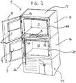
- FIG. 1 there is shown a dual chamber shell sub-assembly for an ultra-low temperature refrigeration system.
- Cabinet 5 is constructed with two independent storage volumes 11, 12 stacked and fastened internally.
- Each cabinet uses cold-wall evaporators (not shown), two hinged interior doors 7, 9 and two exterior doors 8, 10.
- the rear wall (not shown) may be a composite of vacuum insulation panels and expanded polyurethane foam.
- the remaining side walls 13, 14, 15, 16 and top/bottom walls 17, 18, 19, 20 and exterior doors 8, 10 may be homogeneous polyurethane foam.
- the freezer chamber units 22, 24 install within storage volumes 11, 12. Control lines 26 connect to each freezer unit accordingly.
- the wall selection permits high storage efficiency while utilizing a proven door seal interface.
- the use of symmetry reduces the number of parts required to fabricate the cabinet and chambers.
- the refrigeration system is housed in compartment 27.
- the present invention uses refrigerants R404a and R508b in two possible approaches.
- a dual cascade system with a split flow in the low stage circuit comprising a cascade heat exchanger 36, condenser 38, high stage compressor 39, a single low-stage reciprocating compressor 30, a R404a expansion valve 37, R508b expansion valves 34, 35, independent evaporators 31, 32 and an oil separator 33 may be utilized.
- the single low-stage reciprocating compressor 30 supplies refrigerant to the two independent evaporators 31, 32.
- a high-pressure gas stream is split after oil separation occurs.
- the split gas stream passes through the cascade heat exchanger 36.
- the refrigerant R508b expansion valves or electronically controlled expansion valves 34, 35 will meter the refrigerant responsively to varying evaporator loads.
- the refrigerant recombines after leaving the evaporators 31, 32 to return to the low-stage reciprocating compressor 30.
- the separation or split flow allows the two freezer chambers 22, 24 to remain independent while only using a single low-stage reciprocating compressor 30.
- the configuration of using a single low-stage reciprocating compressor to drive both refrigerant loops is efficient and limits operating current in order to utilize any standard 115V-20A power supply.
- a dual cascade system with a split flow in the low stage circuit comprising a cascade heat exchanger 53, condenser 52, high stage reciprocating compressor 48, a single low-stage reciprocating compressor 47, an expansion valve 49, normally open solenoid valves 40, 41, independent evaporators 50, 51, capillary expansion tubes 42, 43, solenoid valves 44, 45 and an oil separator 46 may be utilized.
- a high-pressure refrigerant gas stream is split after oil separation occurs.
- the split gas stream passes through the normally open solenoid valves 40, 41 and into the cascade heat exchanger 53.
- the normally open solenoid valves 40, 41 open refrigerant flow to capillary expansion tubes 42, 43 feeding either chamber 22, 24 in response to the cooling demand.
- Solenoid valves, 44, 45 prevent migration of refrigerant to the active chamber during single chamber 22 or 24 operation.
- the refrigerant recombines after leaving solenoid valves 44, 45 to return to the low-stage reciprocating compressor 47.
- Split flow is complicated by the less responsive capillary expansion tubes 42, 43. However, capillaries are sometimes preferred to expansion valves since capillaries rarely leak or require adjustment.
- the single low-stage compressor 47 is economical and limits operating current in order to utilize any standard 115V-20A power supply.
- a dual cascade system with two independent low-stage cooling circuits 60, 61 comprising a cascade heat exchanger 70, capillary expansion tubes 68, 69, an expansion valve 73, a high stage reciprocating compressor 71, low stage reciprocating compressors 66, 67, oil separators 62, 63, evaporators 64, 65 and a condenser 72 may be utilized.
- a high-pressure gas stream passes through a cascade heat exchanger 70.
- the refrigerant flows to capillary expansion tubes 68, 69 feeding respective chambers 22, 24 in response to the cooling demand of each respective evaporator 64, 65 accordingly.
- This approach avoids flow splitting complications making the system less sensitive to evaporator load differences.
- the system requires simple "on-off' control rather than more complicated flow control strategies. The trade off is higher operating current but it can be managed with smaller, efficient low-stage compressors.
- the present invention may use a life sciences temperature controller 80 having alarm features, self-diagnostics and a cascade system control.
- the temperature controller 80 will need to meet special requirements, for example, at least three inputs, heat exchange, top and bottom chamber temperature readings, two output signals for compressors and/or solenoids, and about two pulsed output signals for electronic expansion valves (not shown). It will also require logic functions, for example, staging multiple compressor start-up, insuring balanced pressure start-up assisting low current/low torque motors, and superheat evaluation functionality.
Landscapes
- Engineering & Computer Science (AREA)
- Physics & Mathematics (AREA)
- Mechanical Engineering (AREA)
- Thermal Sciences (AREA)
- General Engineering & Computer Science (AREA)
- Chemical & Material Sciences (AREA)
- Combustion & Propulsion (AREA)
- Devices That Are Associated With Refrigeration Equipment (AREA)
Claims (12)
- Gefriergerät, umfassend:ein Gehäuse (5),eine erste Gefrierkammer (22) mit ein Paar Seitenwände (13, 14), eine Rückwand, eine Deckenwand (17) und eine Bodenwand (18) beinhaltenden isolierten Begrenzungswänden, die in einem oberen Abschnitt des Gehäuses (5) angeordnet sind,eine zweite Gefrierkammer (24) mit ein Paar Seitenwände (15, 16), eine Rückwand, eine Deckenwand (19) und eine Bodenwand (20) beinhaltenden isolierten Begrenzungswänden, die in einem unteren Abschnitt des Gehäuses (5) angeordnet sind,eine obere isolierte Tür (7), die an einer der Seitenwände der ersten Gefrierkammer (22) angelenkt ist,eine untere isolierte Tür (9), die an einer der Seitenwände der zweiten Gefrierkammer (24) angelenkt ist,wobei das Gehäuse (5) ferner äußere vertikale Türen (8, 10) umfasst, die entlang des oberen bzw. unteren Abschnitts angelenkt sind,ein Kühlaggregat, das ein Zwei-Kaskaden-System umfasst, das einen ersten und einen zweiten Verdampfer umfasst, welche die erste und die zweite Gefrierkammer unabhängig kühlen,und Mittel zum unabhängigen Steuern der Kühlung der ersten und der zweiten Gefrierkammer über das Kühlaggregat,dadurch gekennzeichnet, dassdas Kühlaggregat dafür eingerichtet ist, die erste und die zweite Gefrierkammer (22, 24) auf eine im Wesentlichen einheitliche Temperatur zwischen -40 °C und -80 °C zu kühlen, unddie Kühlmittel R404a und R508b in einem mit der ersten Gefrierkammer (22) und der zweiten Gefrierkammer (24) verbundenen Zwei-Kaskaden-System verwendet werden.
- Gefriergerät nach Anspruch 1, wobei jede der Rückwände Vakuumisolationspaneele und expandierten Polyurethanschaum umfasst.
- Gefriergerät nach Anspruch 2, wobei die Seitenwände (13, 14) und die Decken- und Bodenwand (17, 18) homogenen Polyurethanschaum umfassen.
- Gefriergerät nach Anspruch 1, wobei das Zwei-Kaskaden-System ferner umfasst:einen Kaskadenwärmetauscher (36, 53, 70), der thermodynamisch mit einem Hochstufenkreislauf und einem aufgeteilten Niederstufenkreislauf mit einem Hochdruck-Kühlmittelstrom und einem Niederdruck-Kühlmittelstrom verbunden ist,wobei der aufgeteilte Niederstufenkreislauf unabhängig mit der ersten Gefrierkammer (22) und der zweiten Gefrierkammer (24) verbunden ist.
- Gefriergerät nach Anspruch 4, wobei der aufgeteilte Niederstufenkreislauf umfasst:einen ersten Kreislauf mit einem ersten Verdampfer (31, 50) und einer ersten Expansionseinrichtung (34, 42),einen zweiten Kreislauf mit einem zweiten Verdampfer (32, 51) und einer zweiten Expansionseinrichtung (35, 43),eine Kälteverdichtungseinrichtung (30, 47) undeinen Ölabscheider (33, 46),wobei sich der Hochdruck-Kühlmittelstrom nach Passieren des Ölabscheiders (33, 46) aufteilt und sich der Niederdruck-Kühlmittelstrom nach Passieren des ersten und des zweiten Verdampfers (30, 31, 50, 51) wieder vereinigt.
- Gefriergerät nach Anspruch 5, wobei es sich bei der ersten und der zweiten Expansionseinrichtung (34, 35) um elektronische Expansionseinrichtungen handelt.
- Gefriergerät nach Anspruch 5, wobei es sich bei der ersten und der zweiten Expansionseinrichtung um Kapillarexpansionseinrichtungen (42, 43) handelt.
- Gefriergerät nach Anspruch 7, ferner umfassend:ein erstes Magnetventil (40), das der Aufteilung des Hochdruck-Kühlmittelstroms in den ersten Kreislauf nachgeschaltet ist,ein zweites Magnetventil (41), das der Aufteilung des Hochdruck-Kühlmittelstroms in den zweiten Kreislauf nachgeschaltet ist,ein drittes Magnetventil (44), das dem ersten Verdampfer (50) nachgeschaltet ist, undein viertes Magnetventil (45), das dem zweiten Verdampfer (51) nachgeschaltet ist,wobei das erste und das zweite Magnetventil (40, 41) normalerweise geöffnet sind und das dritte und das vierte Magnetventil (50, 51) während eines Ein-Kammer-Betriebs ein Überwandern von Kühlmittel verhindern.
- Gefrierapparat nach Anspruch 3, wobei das Zwei-Kaskaden-System ferner umfasst:einen Kaskadenwärmetauscher (70), der einen Hochstufenkreislauf und einen ersten undeinen zweiten Niederstufenkreislauf thermodynamisch miteinander verbindet, wobei jeder Niederstufenkreislauf einen Hochdruck-Kühlmittelstrom und einen Niederdruck-Kühlmittelstrom aufweist.
- Gefriergerät nach Anspruch 9, wobei der erste Niederstufenkreislauf und der zweite Niederstufenkreislauf unabhängig durch eine Temperatursteuereinrichtung (80) gesteuert sind.
- Verfahren zum Steuern eines Gefriergeräts nach einem der Ansprüche 1 bis 10, umfassend die Schritte:Bereitstellen eines Zwei-Kaskaden-Systems mit einem Hochstufen- und einem Niederstufenkreislauf, wobei der Hochstufenkreislauf einen Verdichter (39, 48, 71), einen Kondensator (38, 52, 72) und eine Expansionseinrichtung (37, 49, 73) beinhaltet,Aufteilen eines Kühlmittelstroms nach erfolgter Ölabscheidung in einen ersten und einen zweiten Niederstufenkreislauf,Leiten des aufgeteilten Kühlmittelstroms durch eine erste bzw. eine zweite Expansionseinrichtung (34, 35; 42, 43) und einen ersten bzw. einen zweiten Verdampfer (31, 32; 50, 51), Wiedervereinigen des aufgeteilten Kühlmittelstroms nach Passieren des ersten und des zweiten Verdampfers (31, 32; 50, 51) undVerdichten des wiedervereinigten Kühlmittelstroms mit einer Kälteverdichtungseinrichtung (30; 47).
- Verfahren nach Anspruch 11, umfassend die zusätzlichen Schritte:Steuern des Einströmens des aufgeteilten Kühlmittelstroms in einen Kaskadenwärmetauscher mit einem ersten bzw. einem zweiten Magnetventil (40, 41) undSteuern des Überwanderns des aufgeteilten Kühlmittelstroms mit einem dritten bzw. einem vierten Magnetventil (44, 45).
Priority Applications (1)
| Application Number | Priority Date | Filing Date | Title |
|---|---|---|---|
| EP11000997.4A EP2341305B1 (de) | 2002-12-18 | 2003-12-18 | Ultratieftemperaturgefriergerät mit zwei unhabhängigen Kühlkammern |
Applications Claiming Priority (3)
| Application Number | Priority Date | Filing Date | Title |
|---|---|---|---|
| US321584 | 2002-12-18 | ||
| US10/321,584 US6766652B2 (en) | 2002-12-18 | 2002-12-18 | Dual independent chamber ultra-low temperature freezer |
| PCT/US2003/040312 WO2004059226A1 (en) | 2002-12-18 | 2003-12-18 | Dual independent chamber ultra-low temperature freezer |
Related Child Applications (2)
| Application Number | Title | Priority Date | Filing Date |
|---|---|---|---|
| EP11000997.4A Division EP2341305B1 (de) | 2002-12-18 | 2003-12-18 | Ultratieftemperaturgefriergerät mit zwei unhabhängigen Kühlkammern |
| EP11000997.4A Division-Into EP2341305B1 (de) | 2002-12-18 | 2003-12-18 | Ultratieftemperaturgefriergerät mit zwei unhabhängigen Kühlkammern |
Publications (2)
| Publication Number | Publication Date |
|---|---|
| EP1573257A1 EP1573257A1 (de) | 2005-09-14 |
| EP1573257B1 true EP1573257B1 (de) | 2018-08-08 |
Family
ID=32592939
Family Applications (2)
| Application Number | Title | Priority Date | Filing Date |
|---|---|---|---|
| EP11000997.4A Expired - Lifetime EP2341305B1 (de) | 2002-12-18 | 2003-12-18 | Ultratieftemperaturgefriergerät mit zwei unhabhängigen Kühlkammern |
| EP03808470.3A Expired - Lifetime EP1573257B1 (de) | 2002-12-18 | 2003-12-18 | Ultratieftemperaturgefriergerät mit zwei unabhängigen kühlkammern |
Family Applications Before (1)
| Application Number | Title | Priority Date | Filing Date |
|---|---|---|---|
| EP11000997.4A Expired - Lifetime EP2341305B1 (de) | 2002-12-18 | 2003-12-18 | Ultratieftemperaturgefriergerät mit zwei unhabhängigen Kühlkammern |
Country Status (3)
| Country | Link |
|---|---|
| US (1) | US6766652B2 (de) |
| EP (2) | EP2341305B1 (de) |
| WO (1) | WO2004059226A1 (de) |
Families Citing this family (33)
| Publication number | Priority date | Publication date | Assignee | Title |
|---|---|---|---|---|
| CN1878991A (zh) * | 2003-10-08 | 2006-12-13 | 谷轮公司 | 分布式的冷凝单元 |
| US20060130513A1 (en) * | 2004-12-22 | 2006-06-22 | Samsung Electronics Co., Ltd. | Refrigerator |
| TWM302835U (en) * | 2005-04-29 | 2006-12-11 | Interdigital Tech Corp | User equipment and base station for wideband code division multiple access frequency division duplex |
| KR100697088B1 (ko) * | 2005-06-09 | 2007-03-20 | 엘지전자 주식회사 | 공기조화기 |
| JP5026736B2 (ja) * | 2006-05-15 | 2012-09-19 | パナソニックヘルスケア株式会社 | 冷凍装置 |
| JP2007303792A (ja) * | 2006-05-15 | 2007-11-22 | Sanyo Electric Co Ltd | 冷凍装置 |
| US8061153B2 (en) * | 2006-12-28 | 2011-11-22 | Whirlpool Corporation | Refrigeration appliance with optional storage module |
| US20080245086A1 (en) * | 2007-03-02 | 2008-10-09 | Polar King International, Inc. | Multi-zone low temperature freezer |
| CN101688695B (zh) * | 2007-04-23 | 2014-07-23 | 开利公司 | 带增强器回路的co2制冷剂系统 |
| US8794026B2 (en) | 2008-04-18 | 2014-08-05 | Whirlpool Corporation | Secondary cooling apparatus and method for a refrigerator |
| US20100120351A1 (en) * | 2008-11-10 | 2010-05-13 | Thermo Fisher Scientific (Asheville) Llc | Frost reduction by air curtain |
| DE202009010492U1 (de) * | 2009-02-25 | 2010-07-22 | Liebherr-Hausgeräte Ochsenhausen GmbH | Kühl- und/oder Gefriergerät |
| US9217599B2 (en) * | 2009-02-28 | 2015-12-22 | Electrolux Home Products, Inc. | Water introduction into fresh-food icemaker |
| US8011201B2 (en) * | 2009-09-30 | 2011-09-06 | Thermo Fisher Scientific (Asheville) Llc | Refrigeration system mounted within a deck |
| US8011191B2 (en) * | 2009-09-30 | 2011-09-06 | Thermo Fisher Scientific (Asheville) Llc | Refrigeration system having a variable speed compressor |
| CN101893344B (zh) * | 2010-06-24 | 2012-08-15 | 中国科学院理化技术研究所 | 一种混合工质双循环的低温液化系统 |
| DE102011006174B4 (de) * | 2011-03-25 | 2014-07-24 | Bruker Biospin Ag | Kältevorrichtung mit steuerbarer Verdampfungstemperatur |
| EP2532991B1 (de) * | 2011-06-08 | 2019-10-30 | LG Electronics Inc. | Kühlkreislaufvorrichtung und Betriebsverfahren dafür |
| EP2798284B1 (de) * | 2011-10-07 | 2016-12-14 | Danfoss A/S | Verfahren zur koordination des betriebs von verdichtern |
| ES2430714B1 (es) * | 2011-11-11 | 2014-08-27 | Consejo Superior De Investigaciones Científicas (Csic) | Espectrometro automatico multifuncional de alta sensibilidad y su metodo de empleo |
| US8925346B2 (en) | 2012-02-07 | 2015-01-06 | Thermo Fisher Scientific (Asheville) Llc | High performance freezer having cylindrical cabinet |
| JP2014037954A (ja) * | 2012-08-17 | 2014-02-27 | Yutaka Takahashi | 複合ヒートポンプシステム |
| JP2014055753A (ja) * | 2012-09-14 | 2014-03-27 | Hitachi Appliances Inc | 二元冷凍装置 |
| CN105917183B (zh) * | 2012-12-31 | 2018-06-01 | 阿塞里克股份有限公司 | 包括两个冷冻隔室的冰箱 |
| US9140482B2 (en) | 2013-09-30 | 2015-09-22 | Thermo Fisher Scientific (Asheville) Llc | Removable storage basket and associated methods for storing items within a freezer |
| EP3428559B1 (de) * | 2016-03-11 | 2019-12-25 | PHC Holdings Corporation | Ultratieftemperaturgefriergerät |
| US10487570B1 (en) | 2018-07-05 | 2019-11-26 | Schlage Lock Company Llc | Door with interior protective coating |
| CN112923635B (zh) * | 2019-12-05 | 2024-03-05 | 博西华电器(江苏)有限公司 | 制冷器具以及用于制冷器具的方法 |
| EP4030118A1 (de) * | 2021-01-19 | 2022-07-20 | Secop GmbH | Kühleinheit |
| CN113154764A (zh) * | 2021-04-25 | 2021-07-23 | 军事科学院系统工程研究院卫勤保障技术研究所 | 一种适用于高温环境的移动式医用冰箱 |
| DK181274B1 (en) * | 2021-11-05 | 2023-06-16 | Maersk Container Ind A/S | Heat exchanger arrangement and method of controlling same |
| CH718262A1 (de) * | 2022-04-01 | 2022-07-15 | V Zug Ag | Kühlgerät mit einem Kühlkreislauf zum Kühlen des Kondensators. |
| CN119665523B (zh) * | 2025-02-19 | 2025-06-17 | 浙江博开机电科技有限公司 | 一种超低温高效制冷装置 |
Citations (2)
| Publication number | Priority date | Publication date | Assignee | Title |
|---|---|---|---|---|
| EP0845643A2 (de) * | 1996-11-27 | 1998-06-03 | CANDY S.p.A. | Kühlanlage mit veränderlicher Zwangsbelüftung |
| US6161391A (en) * | 1999-08-31 | 2000-12-19 | Trieskey; Guy T. | Environmental test chamber fast cool down system and method therefor |
Family Cites Families (15)
| Publication number | Priority date | Publication date | Assignee | Title |
|---|---|---|---|---|
| US3316731A (en) * | 1965-03-01 | 1967-05-02 | Lester K Quick | Temperature responsive modulating control valve for a refrigeration system |
| US4000626A (en) * | 1975-02-27 | 1977-01-04 | Webber Robert C | Liquid convection fluid heat exchanger for refrigeration circuit |
| GB2083928B (en) * | 1980-09-04 | 1985-01-16 | Gen Electric | Apparatus and method of controlling temperature of a evaporator refrigeration system |
| JPS6078257A (ja) * | 1983-10-03 | 1985-05-02 | 株式会社日立製作所 | 二元冷凍装置 |
| JPS62294855A (ja) * | 1986-05-08 | 1987-12-22 | 三洋電機株式会社 | 冷凍装置 |
| US5335508A (en) * | 1991-08-19 | 1994-08-09 | Tippmann Edward J | Refrigeration system |
| US5447038A (en) * | 1993-11-16 | 1995-09-05 | Reefco Manufacturing Corporation | Apparatus for simultaneously providing multiple temperatures using an automatically configurable cooling system having both cascade and single compressor modes |
| JPH08200921A (ja) * | 1995-01-31 | 1996-08-09 | Sanyo Electric Co Ltd | 急速凍結装置 |
| US5600966A (en) * | 1995-05-19 | 1997-02-11 | Forma Scientific, Inc. | Ultra low temperature split door freezer |
| MY114473A (en) * | 1997-04-08 | 2002-10-31 | Daikin Ind Ltd | Refrigerating system |
| JP3094997B2 (ja) * | 1998-09-30 | 2000-10-03 | ダイキン工業株式会社 | 冷凍装置 |
| JP2000234813A (ja) * | 1999-02-15 | 2000-08-29 | Mitsubishi Electric Corp | 冷凍装置 |
| US6260377B1 (en) * | 1999-03-05 | 2001-07-17 | Sanyo Electric Co., Ltd. | Refrigerating apparatus |
| JP3870048B2 (ja) * | 2001-03-26 | 2007-01-17 | 三星電子株式会社 | マルチルーム型冷蔵庫及びその制御方法 |
| US6557358B2 (en) * | 2001-06-28 | 2003-05-06 | Kendro Laboratory Products, Inc. | Non-hydrocarbon ultra-low temperature system for a refrigeration system |
-
2002
- 2002-12-18 US US10/321,584 patent/US6766652B2/en not_active Expired - Lifetime
-
2003
- 2003-12-18 EP EP11000997.4A patent/EP2341305B1/de not_active Expired - Lifetime
- 2003-12-18 EP EP03808470.3A patent/EP1573257B1/de not_active Expired - Lifetime
- 2003-12-18 WO PCT/US2003/040312 patent/WO2004059226A1/en not_active Ceased
Patent Citations (2)
| Publication number | Priority date | Publication date | Assignee | Title |
|---|---|---|---|---|
| EP0845643A2 (de) * | 1996-11-27 | 1998-06-03 | CANDY S.p.A. | Kühlanlage mit veränderlicher Zwangsbelüftung |
| US6161391A (en) * | 1999-08-31 | 2000-12-19 | Trieskey; Guy T. | Environmental test chamber fast cool down system and method therefor |
Also Published As
| Publication number | Publication date |
|---|---|
| US6766652B2 (en) | 2004-07-27 |
| WO2004059226A1 (en) | 2004-07-15 |
| EP2341305B1 (de) | 2018-09-26 |
| EP2341305A2 (de) | 2011-07-06 |
| EP2341305A3 (de) | 2011-11-09 |
| US20040118139A1 (en) | 2004-06-24 |
| EP1573257A1 (de) | 2005-09-14 |
Similar Documents
| Publication | Publication Date | Title |
|---|---|---|
| US6766652B2 (en) | Dual independent chamber ultra-low temperature freezer | |
| JP3192130B2 (ja) | 冷凍コンテナおよび冷凍システムの運転方法 | |
| US5996356A (en) | Parallel type refrigerator | |
| EP3190356B1 (de) | Kühlschrank und verfahren zur steuerung davon | |
| US5157943A (en) | Refrigeration system including capillary tube/suction line heat transfer | |
| US6758053B2 (en) | Cooling apparatus | |
| JP3847499B2 (ja) | 二段圧縮冷凍冷蔵装置 | |
| EP1957888B1 (de) | Zweitemperaturkältekreislauf | |
| US5447038A (en) | Apparatus for simultaneously providing multiple temperatures using an automatically configurable cooling system having both cascade and single compressor modes | |
| EP0485147A1 (de) | Kühlsystem | |
| WO2009017283A1 (en) | Refrigerator with evaporator installed in door | |
| KR100470476B1 (ko) | 냉동시스템 | |
| JP2002277082A (ja) | 冷凍装置 | |
| KR100550581B1 (ko) | 심온 냉동실을 갖는 냉장고 | |
| JP4240715B2 (ja) | 冷凍冷蔵装置 | |
| JP2004085106A (ja) | 冷凍機および冷蔵庫 | |
| GB2040427A (en) | Single-compressor refrigerator and freezer | |
| KR0136046B1 (ko) | 냉장고의 냉장 및 냉동사이클 진행 제어장치 및 제어방법 | |
| JP2010210133A (ja) | 冷凍サイクル装置 | |
| JPH0534026A (ja) | 冷凍サイクル装置 | |
| KR100522404B1 (ko) | 멀티형 에어컨의 냉동시스템 | |
| JPH02238270A (ja) | 冷凍機のコンデンシングユニット | |
| KR19990056528A (ko) | 식품저장고의 냉동시스템 | |
| KR20020042780A (ko) | 2원 냉동방식을 이용한 다용도 멀티프리저 시스템 | |
| WO2025028243A1 (ja) | 冷凍装置及び制御方法 |
Legal Events
| Date | Code | Title | Description |
|---|---|---|---|
| PUAI | Public reference made under article 153(3) epc to a published international application that has entered the european phase |
Free format text: ORIGINAL CODE: 0009012 |
|
| 17P | Request for examination filed |
Effective date: 20050620 |
|
| AK | Designated contracting states |
Kind code of ref document: A1 Designated state(s): AT BE BG CH CY CZ DE DK EE ES FI FR GB GR HU IE IT LI LU MC NL PT RO SE SI SK TR |
|
| AX | Request for extension of the european patent |
Extension state: AL LT LV MK |
|
| DAX | Request for extension of the european patent (deleted) | ||
| 17Q | First examination report despatched |
Effective date: 20101104 |
|
| RAP1 | Party data changed (applicant data changed or rights of an application transferred) |
Owner name: THERMO FISHER SCIENTIFIC (ASHEVILLE) LLC Owner name: WENG, CHUAN Owner name: KELLY, ALAN |
|
| RAP1 | Party data changed (applicant data changed or rights of an application transferred) |
Owner name: WENG, CHUAN Owner name: THERMO FISHER SCIENTIFIC (ASHEVILLE) LLC |
|
| RIN1 | Information on inventor provided before grant (corrected) |
Inventor name: WENG, CHUAN Inventor name: KELLY, ALAN |
|
| RAP1 | Party data changed (applicant data changed or rights of an application transferred) |
Owner name: THERMO FISHER SCIENTIFIC (ASHEVILLE) LLC |
|
| REG | Reference to a national code |
Ref country code: DE Ref legal event code: R079 Ref document number: 60351387 Country of ref document: DE Free format text: PREVIOUS MAIN CLASS: F25D0011020000 Ipc: F25B0005020000 |
|
| RIC1 | Information provided on ipc code assigned before grant |
Ipc: F25D 23/02 20060101ALI20170331BHEP Ipc: F25B 7/00 20060101ALI20170331BHEP Ipc: F25B 41/04 20060101ALI20170331BHEP Ipc: F25D 11/02 20060101ALI20170331BHEP Ipc: F25B 5/02 20060101AFI20170331BHEP |
|
| GRAP | Despatch of communication of intention to grant a patent |
Free format text: ORIGINAL CODE: EPIDOSNIGR1 |
|
| INTG | Intention to grant announced |
Effective date: 20180426 |
|
| GRAS | Grant fee paid |
Free format text: ORIGINAL CODE: EPIDOSNIGR3 |
|
| GRAA | (expected) grant |
Free format text: ORIGINAL CODE: 0009210 |
|
| AK | Designated contracting states |
Kind code of ref document: B1 Designated state(s): AT BE BG CH CY CZ DE DK EE ES FI FR GB GR HU IE IT LI LU MC NL PT RO SE SI SK TR |
|
| REG | Reference to a national code |
Ref country code: GB Ref legal event code: FG4D |
|
| REG | Reference to a national code |
Ref country code: CH Ref legal event code: EP Ref country code: AT Ref legal event code: REF Ref document number: 1027457 Country of ref document: AT Kind code of ref document: T Effective date: 20180815 |
|
| REG | Reference to a national code |
Ref country code: IE Ref legal event code: FG4D |
|
| REG | Reference to a national code |
Ref country code: DE Ref legal event code: R096 Ref document number: 60351387 Country of ref document: DE |
|
| REG | Reference to a national code |
Ref country code: NL Ref legal event code: MP Effective date: 20180808 |
|
| REG | Reference to a national code |
Ref country code: AT Ref legal event code: MK05 Ref document number: 1027457 Country of ref document: AT Kind code of ref document: T Effective date: 20180808 |
|
| PG25 | Lapsed in a contracting state [announced via postgrant information from national office to epo] |
Ref country code: BG Free format text: LAPSE BECAUSE OF FAILURE TO SUBMIT A TRANSLATION OF THE DESCRIPTION OR TO PAY THE FEE WITHIN THE PRESCRIBED TIME-LIMIT Effective date: 20181108 Ref country code: SE Free format text: LAPSE BECAUSE OF FAILURE TO SUBMIT A TRANSLATION OF THE DESCRIPTION OR TO PAY THE FEE WITHIN THE PRESCRIBED TIME-LIMIT Effective date: 20180808 Ref country code: NL Free format text: LAPSE BECAUSE OF FAILURE TO SUBMIT A TRANSLATION OF THE DESCRIPTION OR TO PAY THE FEE WITHIN THE PRESCRIBED TIME-LIMIT Effective date: 20180808 Ref country code: FI Free format text: LAPSE BECAUSE OF FAILURE TO SUBMIT A TRANSLATION OF THE DESCRIPTION OR TO PAY THE FEE WITHIN THE PRESCRIBED TIME-LIMIT Effective date: 20180808 Ref country code: GR Free format text: LAPSE BECAUSE OF FAILURE TO SUBMIT A TRANSLATION OF THE DESCRIPTION OR TO PAY THE FEE WITHIN THE PRESCRIBED TIME-LIMIT Effective date: 20181109 Ref country code: AT Free format text: LAPSE BECAUSE OF FAILURE TO SUBMIT A TRANSLATION OF THE DESCRIPTION OR TO PAY THE FEE WITHIN THE PRESCRIBED TIME-LIMIT Effective date: 20180808 |
|
| REG | Reference to a national code |
Ref country code: CH Ref legal event code: PK Free format text: BERICHTIGUNGEN |
|
| RIC2 | Information provided on ipc code assigned after grant |
Ipc: F25B 5/02 20060101AFI20170331BHEP Ipc: F25B 41/04 20060101ALI20170331BHEP Ipc: F25D 11/02 20060101ALI20170331BHEP Ipc: F25D 23/02 20060101ALI20170331BHEP Ipc: F25B 7/00 20060101ALI20170331BHEP |
|
| PG25 | Lapsed in a contracting state [announced via postgrant information from national office to epo] |
Ref country code: ES Free format text: LAPSE BECAUSE OF FAILURE TO SUBMIT A TRANSLATION OF THE DESCRIPTION OR TO PAY THE FEE WITHIN THE PRESCRIBED TIME-LIMIT Effective date: 20180808 |
|
| PG25 | Lapsed in a contracting state [announced via postgrant information from national office to epo] |
Ref country code: IT Free format text: LAPSE BECAUSE OF FAILURE TO SUBMIT A TRANSLATION OF THE DESCRIPTION OR TO PAY THE FEE WITHIN THE PRESCRIBED TIME-LIMIT Effective date: 20180808 Ref country code: RO Free format text: LAPSE BECAUSE OF FAILURE TO SUBMIT A TRANSLATION OF THE DESCRIPTION OR TO PAY THE FEE WITHIN THE PRESCRIBED TIME-LIMIT Effective date: 20180808 Ref country code: CZ Free format text: LAPSE BECAUSE OF FAILURE TO SUBMIT A TRANSLATION OF THE DESCRIPTION OR TO PAY THE FEE WITHIN THE PRESCRIBED TIME-LIMIT Effective date: 20180808 Ref country code: EE Free format text: LAPSE BECAUSE OF FAILURE TO SUBMIT A TRANSLATION OF THE DESCRIPTION OR TO PAY THE FEE WITHIN THE PRESCRIBED TIME-LIMIT Effective date: 20180808 |
|
| REG | Reference to a national code |
Ref country code: DE Ref legal event code: R097 Ref document number: 60351387 Country of ref document: DE |
|
| PG25 | Lapsed in a contracting state [announced via postgrant information from national office to epo] |
Ref country code: DK Free format text: LAPSE BECAUSE OF FAILURE TO SUBMIT A TRANSLATION OF THE DESCRIPTION OR TO PAY THE FEE WITHIN THE PRESCRIBED TIME-LIMIT Effective date: 20180808 Ref country code: SK Free format text: LAPSE BECAUSE OF FAILURE TO SUBMIT A TRANSLATION OF THE DESCRIPTION OR TO PAY THE FEE WITHIN THE PRESCRIBED TIME-LIMIT Effective date: 20180808 |
|
| PLBE | No opposition filed within time limit |
Free format text: ORIGINAL CODE: 0009261 |
|
| STAA | Information on the status of an ep patent application or granted ep patent |
Free format text: STATUS: NO OPPOSITION FILED WITHIN TIME LIMIT |
|
| 26N | No opposition filed |
Effective date: 20190509 |
|
| REG | Reference to a national code |
Ref country code: CH Ref legal event code: PL |
|
| PG25 | Lapsed in a contracting state [announced via postgrant information from national office to epo] |
Ref country code: MC Free format text: LAPSE BECAUSE OF FAILURE TO SUBMIT A TRANSLATION OF THE DESCRIPTION OR TO PAY THE FEE WITHIN THE PRESCRIBED TIME-LIMIT Effective date: 20180808 Ref country code: SI Free format text: LAPSE BECAUSE OF FAILURE TO SUBMIT A TRANSLATION OF THE DESCRIPTION OR TO PAY THE FEE WITHIN THE PRESCRIBED TIME-LIMIT Effective date: 20180808 Ref country code: LU Free format text: LAPSE BECAUSE OF NON-PAYMENT OF DUE FEES Effective date: 20181218 |
|
| REG | Reference to a national code |
Ref country code: IE Ref legal event code: MM4A |
|
| REG | Reference to a national code |
Ref country code: BE Ref legal event code: MM Effective date: 20181231 |
|
| PG25 | Lapsed in a contracting state [announced via postgrant information from national office to epo] |
Ref country code: IE Free format text: LAPSE BECAUSE OF NON-PAYMENT OF DUE FEES Effective date: 20181218 |
|
| PG25 | Lapsed in a contracting state [announced via postgrant information from national office to epo] |
Ref country code: BE Free format text: LAPSE BECAUSE OF NON-PAYMENT OF DUE FEES Effective date: 20181231 |
|
| PG25 | Lapsed in a contracting state [announced via postgrant information from national office to epo] |
Ref country code: LI Free format text: LAPSE BECAUSE OF NON-PAYMENT OF DUE FEES Effective date: 20181231 Ref country code: CH Free format text: LAPSE BECAUSE OF NON-PAYMENT OF DUE FEES Effective date: 20181231 |
|
| PG25 | Lapsed in a contracting state [announced via postgrant information from national office to epo] |
Ref country code: TR Free format text: LAPSE BECAUSE OF FAILURE TO SUBMIT A TRANSLATION OF THE DESCRIPTION OR TO PAY THE FEE WITHIN THE PRESCRIBED TIME-LIMIT Effective date: 20180808 |
|
| PG25 | Lapsed in a contracting state [announced via postgrant information from national office to epo] |
Ref country code: PT Free format text: LAPSE BECAUSE OF FAILURE TO SUBMIT A TRANSLATION OF THE DESCRIPTION OR TO PAY THE FEE WITHIN THE PRESCRIBED TIME-LIMIT Effective date: 20180808 |
|
| PG25 | Lapsed in a contracting state [announced via postgrant information from national office to epo] |
Ref country code: HU Free format text: LAPSE BECAUSE OF FAILURE TO SUBMIT A TRANSLATION OF THE DESCRIPTION OR TO PAY THE FEE WITHIN THE PRESCRIBED TIME-LIMIT; INVALID AB INITIO Effective date: 20031218 Ref country code: CY Free format text: LAPSE BECAUSE OF FAILURE TO SUBMIT A TRANSLATION OF THE DESCRIPTION OR TO PAY THE FEE WITHIN THE PRESCRIBED TIME-LIMIT Effective date: 20180808 |
|
| PGFP | Annual fee paid to national office [announced via postgrant information from national office to epo] |
Ref country code: GB Payment date: 20221219 Year of fee payment: 20 Ref country code: FR Payment date: 20221222 Year of fee payment: 20 Ref country code: DE Payment date: 20221130 Year of fee payment: 20 |
|
| REG | Reference to a national code |
Ref country code: DE Ref legal event code: R082 Ref document number: 60351387 Country of ref document: DE Representative=s name: STELLBRINK & PARTNER PATENTANWAELTE MBB, DE |
|
| REG | Reference to a national code |
Ref country code: DE Ref legal event code: R071 Ref document number: 60351387 Country of ref document: DE |
|
| REG | Reference to a national code |
Ref country code: GB Ref legal event code: PE20 Expiry date: 20231217 |
|
| PG25 | Lapsed in a contracting state [announced via postgrant information from national office to epo] |
Ref country code: GB Free format text: LAPSE BECAUSE OF EXPIRATION OF PROTECTION Effective date: 20231217 |
|
| PG25 | Lapsed in a contracting state [announced via postgrant information from national office to epo] |
Ref country code: GB Free format text: LAPSE BECAUSE OF EXPIRATION OF PROTECTION Effective date: 20231217 |