EP1571075A1 - Einsatz für Fahrradtretkurbel - Google Patents
Einsatz für Fahrradtretkurbel Download PDFInfo
- Publication number
- EP1571075A1 EP1571075A1 EP04425151A EP04425151A EP1571075A1 EP 1571075 A1 EP1571075 A1 EP 1571075A1 EP 04425151 A EP04425151 A EP 04425151A EP 04425151 A EP04425151 A EP 04425151A EP 1571075 A1 EP1571075 A1 EP 1571075A1
- Authority
- EP
- European Patent Office
- Prior art keywords
- insert
- pedal crank
- fibres
- mould
- polymeric material
- Prior art date
- Legal status (The legal status is an assumption and is not a legal conclusion. Google has not performed a legal analysis and makes no representation as to the accuracy of the status listed.)
- Granted
Links
- 239000000463 material Substances 0.000 claims abstract description 54
- 239000004744 fabric Substances 0.000 claims description 34
- 239000002131 composite material Substances 0.000 claims description 32
- 238000000034 method Methods 0.000 claims description 28
- 229920005989 resin Polymers 0.000 claims description 11
- 239000011347 resin Substances 0.000 claims description 11
- 229920005992 thermoplastic resin Polymers 0.000 claims description 10
- OKTJSMMVPCPJKN-UHFFFAOYSA-N Carbon Chemical compound [C] OKTJSMMVPCPJKN-UHFFFAOYSA-N 0.000 claims description 6
- 229910052799 carbon Inorganic materials 0.000 claims description 6
- ZOXJGFHDIHLPTG-UHFFFAOYSA-N Boron Chemical compound [B] ZOXJGFHDIHLPTG-UHFFFAOYSA-N 0.000 claims description 3
- 229910052796 boron Inorganic materials 0.000 claims description 3
- 239000000919 ceramic Substances 0.000 claims description 3
- 239000003365 glass fiber Substances 0.000 claims description 3
- 230000002093 peripheral effect Effects 0.000 claims description 2
- 238000009941 weaving Methods 0.000 claims description 2
- 238000007493 shaping process Methods 0.000 claims 1
- 238000001816 cooling Methods 0.000 description 10
- 239000004033 plastic Substances 0.000 description 5
- 230000008878 coupling Effects 0.000 description 4
- 238000010168 coupling process Methods 0.000 description 4
- 238000005859 coupling reaction Methods 0.000 description 4
- 239000000835 fiber Substances 0.000 description 3
- 238000000465 moulding Methods 0.000 description 3
- 230000007704 transition Effects 0.000 description 3
- 239000004411 aluminium Substances 0.000 description 2
- 229910052782 aluminium Inorganic materials 0.000 description 2
- XAGFODPZIPBFFR-UHFFFAOYSA-N aluminium Chemical compound [Al] XAGFODPZIPBFFR-UHFFFAOYSA-N 0.000 description 2
- -1 aramidic fibres Substances 0.000 description 2
- 239000000155 melt Substances 0.000 description 2
- 239000002184 metal Substances 0.000 description 2
- 229910052751 metal Inorganic materials 0.000 description 2
- 239000007769 metal material Substances 0.000 description 2
- 238000003801 milling Methods 0.000 description 2
- 239000002245 particle Substances 0.000 description 2
- 230000008569 process Effects 0.000 description 2
- 238000012545 processing Methods 0.000 description 2
- XLYOFNOQVPJJNP-UHFFFAOYSA-N water Substances O XLYOFNOQVPJJNP-UHFFFAOYSA-N 0.000 description 2
- 230000009471 action Effects 0.000 description 1
- 230000005540 biological transmission Effects 0.000 description 1
- 238000013461 design Methods 0.000 description 1
- 238000003780 insertion Methods 0.000 description 1
- 230000037431 insertion Effects 0.000 description 1
- 239000013067 intermediate product Substances 0.000 description 1
- 238000002844 melting Methods 0.000 description 1
- 230000008018 melting Effects 0.000 description 1
- 230000001737 promoting effect Effects 0.000 description 1
- 238000011160 research Methods 0.000 description 1
- 229920001169 thermoplastic Polymers 0.000 description 1
- 239000012815 thermoplastic material Substances 0.000 description 1
- 239000004416 thermosoftening plastic Substances 0.000 description 1
Images

Classifications
-
- B—PERFORMING OPERATIONS; TRANSPORTING
- B62—LAND VEHICLES FOR TRAVELLING OTHERWISE THAN ON RAILS
- B62M—RIDER PROPULSION OF WHEELED VEHICLES OR SLEDGES; POWERED PROPULSION OF SLEDGES OR SINGLE-TRACK CYCLES; TRANSMISSIONS SPECIALLY ADAPTED FOR SUCH VEHICLES
- B62M3/00—Construction of cranks operated by hand or foot
-
- B—PERFORMING OPERATIONS; TRANSPORTING
- B62—LAND VEHICLES FOR TRAVELLING OTHERWISE THAN ON RAILS
- B62K—CYCLES; CYCLE FRAMES; CYCLE STEERING DEVICES; RIDER-OPERATED TERMINAL CONTROLS SPECIALLY ADAPTED FOR CYCLES; CYCLE AXLE SUSPENSIONS; CYCLE SIDE-CARS, FORECARS, OR THE LIKE
- B62K19/00—Cycle frames
- B62K19/02—Cycle frames characterised by material or cross-section of frame members
- B62K19/16—Cycle frames characterised by material or cross-section of frame members the material being wholly or mainly of plastics
-
- Y—GENERAL TAGGING OF NEW TECHNOLOGICAL DEVELOPMENTS; GENERAL TAGGING OF CROSS-SECTIONAL TECHNOLOGIES SPANNING OVER SEVERAL SECTIONS OF THE IPC; TECHNICAL SUBJECTS COVERED BY FORMER USPC CROSS-REFERENCE ART COLLECTIONS [XRACs] AND DIGESTS
- Y10—TECHNICAL SUBJECTS COVERED BY FORMER USPC
- Y10T—TECHNICAL SUBJECTS COVERED BY FORMER US CLASSIFICATION
- Y10T74/00—Machine element or mechanism
- Y10T74/21—Elements
- Y10T74/2164—Cranks and pedals
Definitions
- the present invention refers to an insert for a bicycle pedal crank and to a method suitable for making such an insert.
- the invention also refers to a pedal crank incorporating such an insert and to a method for obtaining it.
- Such pedal cranks are made by moulding of a thermo-setting composite material inside a mould where such metallic inserts are arranged.
- the composite material in plastic state is arranged to cover the inserts, surrounding them for a large part of their outer surface.
- the material thus arranged inside the mould is heated and simultaneously subjected to a suitable pressure until it is reticulated.
- the pedal crank then undergoes a cooling until it reaches room temperature.
- the composite material that surrounds the metallic insert tends to detach from the walls of the insert itself.
- the metallic material of which the insert consists shrinks more than the composite material of the pedal crank body and the degree of detachment is all the greater the greater the difference of the cooling coefficient of the two materials.
- Such a detachment involves a decrease in adherence between the metal insert and the composite material, with a consequent decrease in the properties of resistance and hold of the interface zones.
- the purpose of the present invention is that of overcoming said drawback.
- a first purpose of the invention is that of making an insert for a pedal crank that does not detach and at the same time that ensures sufficient resistance for the interface zones in which it is arranged.
- Another purpose of the invention is to make an insert for a pedal crank that gives the pedal crank itself a lower weight with respect to known pedal cranks with metallic inserts.
- a first aspect of the invention lies in an insert for a bicycle pedal crank characterised in that it is made with unidirectional structural fibres incorporated in a polymeric material and coupled according to at least two distinct directions and in that it has a connection portion to a part of the bicycle and a fastening portion to the body of the pedal crank.
- the unidirectional structural fibres coupled according to many directions give the insert a high mechanical rigidity and allow its direct connection to the bicycle parts.
- the insert is made by piling up many sheets of unidirectional fibres in which each sheet consists of unidirectional fibres woven together to make a typical fabric structure with warp and weft.
- the insert has a substantially elongated shape along a main axis, in which the fastening portion is contiguous to the connection portion along such an axis.
- the length of the connection portion is slightly greater than the length of the fastening portion.
- the insert has a substantially tubular shape in which the connection portion is defined on the inner surface of the tubular body and the fastening portion is defined on the outer surface of the tubular body.
- the insert of the invention has, in the connection portion, a through hole, possibly threaded, to allow the connection to the parts of the bicycle, like for example the toothed crowns, the pin of the pedal or the pin of the bottom bracket.
- a second aspect of the invention lies in a method for making an insert for a bicycle pedal crank with unidirectional structural fibres incorporated in a polymeric material, coupled according to at least two distinct directions, characterised in that it comprises the steps of:
- a further step of making a through hole in the connection zone of the insert is provided.
- a bicycle pedal crank characterised in that it comprises a main body at least partially consisting of a composite material consisting of structural fibres incorporated in a polymeric material and in that it comprises one or more of the aforementioned inserts.
- the main body of the pedal crank consists entirely of the composite material consisting of structural fibres incorporated in a polymeric material.
- the polymeric material of which the composite material of the body of the pedal crank consists is substantially the same as the polymeric material that incorporates the unidirectional fibres of which the inserts consist.
- the inserts are inserted in the attachment zones of the pedal crank to the toothed crowns, in the attachment zone to the bottom bracket and in the attachment zone to the pin of the pedal so as to make a pedal crank completely in composite material.
- a further aspect of the invention lies in a method for making a pedal crank comprising a main body at least partially consisting of a composite material consisting of structural fibres incorporated in a polymeric material, characterised in that it comprises the steps of:
- the through hole in the connection zone of the insert is made after the pedal crank is removed from the mould, to allow the exact centring of the hole itself with respect to the bicycle part intended to be connected to the pedal crank, in particular during the assembly step of the toothed crowns to the pedal crank.
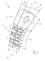
- the insert of the invention is represented in fig. 1 and is wholly indicated with 1.
- the insert 1 has an elongated slightly arched shape and extends along the main axis X-X. It essentially consists of a connection portion 2 and a fastening portion 4 that extend contiguously along the main axis X-X.
- the fastening portion 4 of the insert 1 has, in its outer surface, a plurality of depression zones 7a, 7b. More specifically, first depression zones 7a extend on the outer peripheral surface of the fastening portion 4 for all of its thickness S2 and consist of substantially cylindrical surfaces. Second depression zones 7b engage the interfacing surfaces 4a and 4b of the fastening portion 4 and consist of cuts that partially engage the thickness S2 of the fastening portion 4 itself. In different embodiments, such depressions 7b could, nevertheless, engage the fastening portion 4 for all of its thickness S2, substantially making through holes.
- connection portion 2 has a through hole 6.
- the fastening portion 4 has a length L2 slightly greater than the length L1 of the first portion 2, whereas its width H2 is less than the width H1 of the first portion.
- the thicknesses S1 and S2 of the connection and fastening portions 2 and 4, on the other hand, are substantially the same.
- connection and fastening portions 2 and 4 are connected through two surfaces 8 and 9 having a circular profile of radius R.
- the curvilinear progression of such surfaces allows the tensions to which the insert 1 is subjected in the transition zone between the connection and fastening portions 2 and 4 to be uniformly distributed.
- the value of the radius R is suitably chosen, in the design phase, based upon the force components to which the insert 1 is subjected.
- the insert 1 is made through the piling up of many sheets of unidirectional structural fibres incorporated in a polymeric material coupled together according to two distinct directions.
- the unidirectional structural fibres are orientated according to two perpendicular directions and are woven together to define the weft and the warp of a sheet of fabric, commonly known as plain fabric.
- the insert 1 is thus obtained through the piling up of a number of sheets of fabric in a sufficient number to reach the desired thickness S1 (S2).
- the sheets of fabric used typically have a thickness of between 0.3 and 0.5 mm whereas the thickness S1 (S2) of the insert 1 is in the order of 5 mm, for which reason between 10 and 17 sheets of fabric are used.
- the fabric obtained from the weaving of unidirectional fibres of warp and weft can have, in different embodiments, any known weave, like for example a "twill” or "satin” fabric.
- the weft fibres are present in the fabric with the same percentage by weight of the warp fibres.
- the unidirectional structural fibres are incorporated in distinct sheets, each containing fibres orientated in a single direction.
- the insert 1 is obtained by piling up a plurality of such sheets, arranging them so that the directions of the unidirectional fibres that they incorporate do not all coincide.
- the sheets of unidirectional fibres are piled up so that the unidirectional fibres are aligned according to two directions perpendicular to each other.
- the sheets of unidirectional fibres are piled up and angularly staggered according to many directions, so as to define a substantially isotropic structure with unidirectional structural fibres distributed on many directions.
- the insert 1 is made by piling up many sheets of the type described above according to any combination, like for example sheets of fabric alternated by sheets of just unidirectional fibres angularly staggered from each other.
- the unidirectional structural fibres are chosen from the group consisting of carbon fibres, glass fibres, aramidic fibres, ceramic fibres, boron fibres and combinations thereof, carbon fibre being preferred.
- the polymeric material can consist of a thermo-setting plastic material or a thermoplastic material, with different known treatment processes according to the chosen material, as we shall see later on.
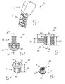
- a variant embodiment of the insert 20 is represented that differs from the embodiment described previously in that it does not have the through hole 6 in the connection portion 2.
- a variant embodiment of the insert is represented, indicated with 50.
- the insert 50 differs from the insert described with reference to fig. 1 in that it has the connection portion 52 with a thickness S1 greater than the thickness S2 of the fastening portion 54 and, moreover, the hole 56 in the connection portion 52 is threaded.
- the thickness S1 of the insert 50 is in the order of 14 mm, whereas the thickness S2 is about half the thickness S4, i.e. about 7 mm.
- the sheets of fabric used typically have a thickness of between 0.3 and 0.5 mm, for which reason to obtain the desired thicknesses S1 and S4 between 14 and 23 sheets of fabric for S3 and between 28 and 46 sheets of fabric for S4 are used, respectively.
- the insert 70 has a substantially tubular shape in which a connection portion 72 and a fastening portion 74 are defined.
- the connection portion 72 consists of a square hole 76 formed on the inner surface of the tubular body, whereas the fastening portion 74 consists of depressions in the form of grooves 77 that extend on the outer surface of the tubular body for almost the entire thickness S3 of the insert 70, of about 22 mm.
- the insert 80 has a substantially tubular shape in which a connection portion 82 and a fastening portion 84 are defined.
- the connection portion 82 consists of a threaded hole 86 coinciding with the inner surface of the tubular body, whereas the fastening portion 84 consists of depressions 87 in the form of grooves that extend on the outer surface of the tubular body for almost the entire thickness S4 of the insert 80, of about 14 mm.
- an insert 1, 20, of the type represented in figures 1 and 2 according to the present invention is made with the method described hereafter.
- a predetermined number of sheets of fabric are piled up so as to fill the mould for the desired thickness.
- Each sheet of fabric is formed of unidirectional structural fibres of carbon fibre, crossed according to two directions, of warp and weft, perpendicular to each other in a configuration commonly called "plain".
- the fabric is arranged in the mould so that one of the two warp and weft directions is substantially parallel to the main axis X-X of the insert 1, 20.
- the fibres in the sheets of fabric are impregnated with a thermo-setting resin.
- the mould is then closet through a second semi-mould that couples with the first semi-mould to internally define a chamber with a shape matching the outer shape of the insert 1, 20.
- the two semi-moulds are then subjected to a temperature and pressure profile such as to cause the cross-linkage of the thermo-setting resin giving the sheets of fabric the compact structure with the desired shape of insert. More specifically, the temperature of the thermo-setting resin is raised from a room temperature value, when the sheets of fabric are positioned in the mould and the resin possesses a degree of plasticity such as to allow the cascade of the sheets of fabric, up to its cross-linkage temperature, i.e. when it takes up a rigid structure. With cross-linkage complete, the insert is left to cool and is then removed from the mould.
- the unidirectional fibres can also be incorporated in a thermoplastic resin.
- the temperature and pressure profile firstly provides that the temperature of the thermoplastic resin be raised from a room temperature value, when the sheets of fabric are positioned in the mould and the resin is substantially rigid, up to its vitreous transition temperature.
- the thermoplastic resin of the various sheets of fabric melts, giving a plastic consistency to the piled up sheets of fabric that take up, under pressure, the shape of the mould.
- a second cooling step of the mould during which the thermoplastic resin, cooling down, regains the desired rigidity.
- the mould is then opened and the insert is removed.
- thermosetting we therefore mean the cross-linkage process, in the case in which the resin used is of the thermo-setting type, whereas we mean a melting followed by cooling in the case in which the resin used is of the thermoplastic type.
- the steps of the method described up to here allow an insert 20 of the type shown in fig. 2 to be obtained, in other words the same element of fig. 1 with the exception of the fact that it does not have the hole 6.
- the hole 6 on each insert 20 is made after it has been inserted in the pedal crank, as we shall see hereafter.
- the hole 6 can be made on the insert 20 obtained with the previous method through mechanical processing, for example milling, boring or through cutting with a high pressure beam of concentrated water incorporating abrasive particles.
- the hole 6 can be obtained directly during the previous moulding steps, taking care to suitably perforate the sheets of fabric before their insertion in the mould and thus before the thermal setting treatment of the thermo-setting or thermoplastic resin.
- the same method described above can be used, in which the filling step of the mould through the piling up of sheets of fabric firstly provides for arranging a predetermined number of sheets of fabric of length L1 for a thickness S5, then piling a predetermined number of sheets of fabric of length L1+L2 for a thickness S2 and finally piling up a predetermined number of sheets of fabric of length L1 for a thickness S6.
- the aforementioned inserts 1, 20, 50, and their variations in thickness can be obtained starting from a monolithic element, with a substantially parallelepiped shape, consisting of piled up sheets of fabric subjected to the previous moulding cycle with setting, on which subsequent mechanical removal operations are carried out to obtain the desired profiles.
- the sheets of can have a weave with a different configuration, like for example "twill", "satin” or other type weave, or else furthermore the fabric can have different percentages of weight between warp and weft.
- each sheet inserted in the mould consists of just unidirectional structural fibres and the desired thickness is obtained by alternately piling up a predetermined number of sheets according to perpendicular directions.
- each sheet inserted in the mould consists of just unidirectional structural fibres and the desired thickness is obtained by alternately piling up a predetermined number of sheets according to angularly staggered directions, so as to obtain a substantially isotropic structure with unidirectional fibres distributed homogeneously over 360°.
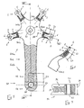
- a pedal crank with spokes 100 is represented, commonly known as right pedal crank, suitable for being connected to the bottom bracket of the bicycle, to the pedal and for receiving two or more toothed crowns in mechanical coupling.
- Such a type of pedal crank 100 substantially has a main body 102 having a first end 102a provided for the connection to the bottom bracket and for the connection of the toothed crowns, not represented, and a second end 102b provided to receive the pin of a pedal, also not represented.
- spokes 101a-101d are made at the ends of which respective inserts 1 or 20 of the type represented in fig. 1 are inserted.
- the inserts 1 have the toothed crowns fixed to them, on which the chain is wound for the transmission of the movement from the pedal to the rear wheel.
- a known attachment method of the toothed crowns to the pedal crank with spokes 100 provides, for example, the use of attachment screws arranged passing into the holes 6 of the inserts 1 that lock the sprockets to the spokes 101a-101d through corresponding attachment nuts.
- each insert 1 is totally enclosed by the material that constitutes the end of the corresponding spoke 101a-101d.
- the material that constitutes the pedal crank 100 fills the depressions 7a and 7b of the fastening portion 4, with the consequent increase in contact surfaces and the increase in adherence between the body of the pedal crank and the insert 1.
- the characteristics that the length L2 of the fastening portion 4 incorporated in the body of the pedal crank 100 is greater than the length L1 of the connection portion 2 projecting from the ends of the spokes 101a-101d, allows a high stability of the insert 1, and in particular a high rigidity to be obtained that counteracts possible flexing of the insert along its main axis X-X.
- the second end 102b of the pedal crank 100 there is an insert 50 of the type shown in figs. 3 and 4, which allows the connection of a pedal receiving in engagement in the threaded hole 56 the threaded pin of the pedal, not represented.
- the thickness S1 of the connection portion 52 which is greater than the thickness S2 of the fastening portion 54, allows a smooth progression of the outer surface of the pedal crank 100 to be obtained, promoting the attachment of the pedal to the pedal crank 100 itself.
- the fastening portion 54 of the insert 50 is totally enclosed by the material that constitutes the body of the pedal crank 100, determining a high adherence between the body of the pedal crank 100 and the insert 50 itself.
- the stability of the insert 50, and in particular the rigidity with respect to flexing along its main axis X-X is obtained thanks to the fact that the length L2 of the fastening portion 54 incorporated in the body of the pedal crank 100 is greater than the length L1 of the connection portion 52 projecting from the end of the pedal crank 100.
- a pedal crank 200 is represented, commonly known as left pedal crank, consisting of a main body 202 having a first end 202a provided for the connection to the bottom bracket, not represented, and a second end 202b provided to receive the pin of a pedal, also not represented.
- the insert 70 of the type represented in fig. 5 to the square hole of which 76 the pin of the bottom bracket is fixed in a known way.
- the fastening portion 74 of the insert 70, and in particular the grooves 77, are totally enclosed by the material that constitutes the body of the pedal crank 200 determining a high adherence between the body of the pedal crank 200 and the insert 70 itself.
- the fastening portion 84 of the insert 80 and in particular the grooves 87, are totally enclosed by the material that constitutes the body of the pedal crank 200 determining a high adherence between the body of the pedal crank 200 and the insert 80 itself.
- the main body 102, 202 advantageously consists of a composite material consisting of structural fibres incorporated in a polymeric material, the fibres of the composite material being able to be arranged in the polymeric material both in a disordered manner, for example in the form of small sheets or pieces of fibres arranged randomly, and in an ordered manner to form a typical fabric structure.
- the structural fibres like for the insert, are chosen from the group consisting of carbon fibres, glass fibres, aramidic fibres, ceramic fibres, boron fibres and combinations thereof, carbon fibre being preferred.
- the polymeric material with which the composite of the pedal crank is made is advantageously chosen of the same type as the polymeric material used to make the inserts 1, 50, 70, 80, in the case in point a thermo-setting resin.
- the right or left pedal crank can provide for the use both of inserts of the type described and inserts of the conventional type made from aluminium or metallic material.
- a right pedal crank can have the inserts 1 for the attachment to the toothed crowns of the type described in the present invention, whereas the inserts for the attachment to the bottom bracket and to the pedal can be made from aluminium.
- the body of the pedal crank can be not entirely made from composite material consisting of structural fibres incorporated in a polymeric material, but have parts of different material or recesses, like for example a hollow metallic core or a core of plastic material, according to that which is described in patent applications EP 1270393, EP 1270394 and EP 1281609 to the same Applicant, incorporated here for reference.
- a right or left pedal crank 100, 200 of the type described above is made with the method described hereafter.
- the inserts 1, 50, 70, 80 are positioned in the corresponding zones relative to the attachment of the toothed crowns, to the attachment to the bottom bracket and to the attachment to the pin of the pedal. Then the composite material that constitutes the body 102, 202 of the pedal crank 100, 200 is arranged in the mould. The mould is then closed through a second semi-mould that couples with the first semi-mould to internally define a chamber with a shape matching the outer shape of the pedal crank 100, 200.
- the composite material is then subjected to a pressure such as to allow it to be arranged to fill the mould and in particular to be arranged in contact with the fastening portion 4, 54, 74, 84 of the inserts 1, 50, 70, 80.
- the two semi-moulds are then subjected to a temperature profile such as to cause the setting of the polymeric material that constitutes the composite material of the pedal crank.
- a temperature profile such as to cause the setting of the polymeric material that constitutes the composite material of the pedal crank.
- the temperature of the thermo-setting resin is raised, from a room temperature value, up to its cross-linkage temperature, i.e. when it takes up a rigid structure.
- the coupling between the composite material and the fastening portions 4, 54, 74, 84 of the inserts 1, 50, 70, 80 is thus made.
- the pedal crank 100, 200 is left to cool and is then removed from the mould.
- the temperature and pressure profile firstly provides that the temperature of the thermoplastic resin is raised, from a room temperature value, up to its vitreous transition temperature. At such a temperature the thermoplastic resin melts, giving a plastic consistency to the composite material that takes up, under pressure, the shape of the mould. Then follows a second cooling step of the mould during which the thermoplastic resin, cooling down, regains the desired rigidity. The mould is then opened and the pedal crank 100, 200 is removed.
- the polymeric material with which the body of the pedal crank 100, 200 is made is the same as the polymeric material used for making the inserts 1, 20, 50, 70, 80.
- the thermal coefficients of the parts that are co-moulded, i.e. the body of the pedal crank 100, 200 and the inserts 1, 20, 50, 70, 80, are substantially the same and the coupling between the pedal crank and the inserts has maximum adhesion.
Landscapes
- Engineering & Computer Science (AREA)
- Mechanical Engineering (AREA)
- Chemical & Material Sciences (AREA)
- Combustion & Propulsion (AREA)
- Transportation (AREA)
- Moulding By Coating Moulds (AREA)
- Reinforced Plastic Materials (AREA)
- Shafts, Cranks, Connecting Bars, And Related Bearings (AREA)
- Injection Moulding Of Plastics Or The Like (AREA)
Priority Applications (7)
| Application Number | Priority Date | Filing Date | Title |
|---|---|---|---|
| EP04425151A EP1571075B1 (de) | 2004-03-05 | 2004-03-05 | Einsatz für Fahrradtretkurbel |
| DE602004010780T DE602004010780T2 (de) | 2004-03-05 | 2004-03-05 | Einsatz für Fahrradtretkurbel |
| ES04425151T ES2297364T3 (es) | 2004-03-05 | 2004-03-05 | Injerto para manivela de pedal de bicicleta. |
| AT04425151T ATE381481T1 (de) | 2004-03-05 | 2004-03-05 | Einsatz für fahrradtretkurbel |
| TW094105099A TW200530076A (en) | 2004-03-05 | 2005-02-21 | Insert for a bicycle pedal crank, pedal crank comprising such an insert and methods suitable for making such an insert and such a pedal crank |
| CN200510053096.9A CN1724307A (zh) | 2004-03-05 | 2005-03-07 | 自行车踏板曲柄、用于踏板曲柄的镶嵌件、及其制造方法 |
| US11/074,290 US20050199092A1 (en) | 2004-03-05 | 2005-03-07 | Insert for a bicycle pedal crank, pedal crank comprising such an insert and methods suitable for making such an insert and such a pedal crank |
Applications Claiming Priority (1)
| Application Number | Priority Date | Filing Date | Title |
|---|---|---|---|
| EP04425151A EP1571075B1 (de) | 2004-03-05 | 2004-03-05 | Einsatz für Fahrradtretkurbel |
Publications (2)
| Publication Number | Publication Date |
|---|---|
| EP1571075A1 true EP1571075A1 (de) | 2005-09-07 |
| EP1571075B1 EP1571075B1 (de) | 2007-12-19 |
Family
ID=34746233
Family Applications (1)
| Application Number | Title | Priority Date | Filing Date |
|---|---|---|---|
| EP04425151A Expired - Lifetime EP1571075B1 (de) | 2004-03-05 | 2004-03-05 | Einsatz für Fahrradtretkurbel |
Country Status (7)
| Country | Link |
|---|---|
| US (1) | US20050199092A1 (de) |
| EP (1) | EP1571075B1 (de) |
| CN (1) | CN1724307A (de) |
| AT (1) | ATE381481T1 (de) |
| DE (1) | DE602004010780T2 (de) |
| ES (1) | ES2297364T3 (de) |
| TW (1) | TW200530076A (de) |
Cited By (2)
| Publication number | Priority date | Publication date | Assignee | Title |
|---|---|---|---|---|
| EP1749736A1 (de) | 2005-08-03 | 2007-02-07 | Campagnolo S.R.L. | Fahrradkomponente aus Verbundwerkstoff mit Einsätzen und deren Herstellung |
| GB2566471A (en) * | 2017-09-14 | 2019-03-20 | Chin Long Hsieh | Assembling structure for crank and pedal |
Families Citing this family (23)
| Publication number | Priority date | Publication date | Assignee | Title |
|---|---|---|---|---|
| FR2874203A1 (fr) * | 2004-08-13 | 2006-02-17 | Stronglight Sa Sa | Manivelle pour cycles |
| EP1759980A1 (de) * | 2005-06-17 | 2007-03-07 | Campagnolo Srl | Einsatz zur Befestigung von Fahrradbauteilen und Fahrradbauteile mit solch einem Einsatz |
| DE102007058587A1 (de) * | 2007-12-04 | 2009-06-10 | Dt Swiss Ag | Gabelkrone und Verfahren zur Herstellung, insbesondere für Fahrräder |
| EP2179838B1 (de) * | 2008-10-23 | 2017-12-06 | Campagnolo S.r.l. | Plattenformungsverbindung |
| TWM358112U (en) * | 2009-01-21 | 2009-06-01 | Guang-Xiong Liu | Sensing structure of bicycle power assistance system |
| US20100275724A1 (en) * | 2009-04-29 | 2010-11-04 | Race Face Components Inc. | Insert for bicycle crank arm |
| US8820192B2 (en) | 2009-04-29 | 2014-09-02 | Race Face Prerformance Products Inc. | Bicycle crank arm and insert therefore |
| CN102887199B (zh) * | 2012-09-29 | 2014-02-26 | 张卫兵 | 一种碳纤维自行车曲柄及其制造工艺 |
| WO2015095042A1 (en) * | 2013-12-16 | 2015-06-25 | Borgwarner Inc. | Composite tensioner arm or guide for timing drive application |
| US10562588B2 (en) | 2015-09-01 | 2020-02-18 | The Hive Global, Inc | Bicycle cassette with locking connection |
| US11142280B2 (en) | 2016-03-24 | 2021-10-12 | The Hive Global, Inc. | Bicycle crank with spindle attachment structure |
| EP3239035A1 (de) | 2016-04-11 | 2017-11-01 | Fox Factory, Inc. | Vorderes fahrradkettenrad |
| TWM550261U (zh) * | 2016-11-04 | 2017-10-11 | Cherub Cycle Enterprise Co Ltd | 雙用童車 |
| US11014628B2 (en) | 2017-04-28 | 2021-05-25 | Fox Factory, Inc. | Cinch direct mount 2X ring system |
| CN111542471A (zh) | 2017-08-21 | 2020-08-14 | 劲锋铁马股份有限公司 | 具有夹紧连接的自行车塔轮 |
| IT201800005294A1 (it) | 2018-05-11 | 2019-11-11 | Componente di bicicletta in materiale composito e relativo processo di fabbricazione | |
| TWI804619B (zh) | 2018-05-11 | 2023-06-11 | 義大利商坎帕克諾羅公司 | 設有電氣/電子系統的自行車曲柄臂 |
| IT201800005302A1 (it) | 2018-05-11 | 2019-11-11 | Pedivella di bicicletta dal lato trasmissione, dotata di rilevatore di sforzi/deformazioni per un misuratore di coppia o di potenza, nonche' metodi correlati | |
| IT201800005297A1 (it) | 2018-05-11 | 2019-11-11 | Pedivella di bicicletta e relativa guarnitura | |
| IT201800005299A1 (it) | 2018-05-11 | 2019-11-11 | Componente di bicicletta dotato di sensore di sforzi/deformazioni compensato in temperatura | |
| US11359709B2 (en) | 2018-12-18 | 2022-06-14 | Fox Factory, Inc. | Chainring |
| US11680633B2 (en) | 2019-02-08 | 2023-06-20 | Fox Factory, Inc. | Chainring |
| US11932351B2 (en) | 2020-07-17 | 2024-03-19 | The Hive Global, Inc. | Conical bicycle cassette sprocket structure |
Citations (7)
| Publication number | Priority date | Publication date | Assignee | Title |
|---|---|---|---|---|
| FR2605968A1 (fr) * | 1986-10-31 | 1988-05-06 | Bezin Michel | Manivelle pour pedalier de bicyclette |
| JPH06321167A (ja) * | 1993-05-14 | 1994-11-22 | Mitsubishi Rayon Co Ltd | 自転車用クランク |
| US5435869A (en) * | 1993-08-27 | 1995-07-25 | Christensen; Roland | Method for manufacturing a composite crank arm |
| US5624519A (en) * | 1992-05-29 | 1997-04-29 | Trek Bicycle, Corp. | Method making a composite bicycle frame using composite lugs |
| EP1270394A1 (de) | 2001-06-27 | 2003-01-02 | Campagnolo Srl | Fahrrad-Kurbel und ihre Fertigungsmethode |
| EP1270393A1 (de) | 2001-06-27 | 2003-01-02 | Campagnolo S.R.L. | Fahrradkurbel und ihre Fertigungsmethode |
| EP1281609A2 (de) | 2001-08-03 | 2003-02-05 | Campagnolo S.R.L. | Verfahren zur Herstellung von einem Kurbelhebel eines Fahrrads |
Family Cites Families (7)
| Publication number | Priority date | Publication date | Assignee | Title |
|---|---|---|---|---|
| EP0270388B1 (de) * | 1986-10-31 | 1990-07-18 | Look Sté. | Kurbel für Tretlager eines Fahrrads |
| DE29608748U1 (de) * | 1996-05-14 | 1996-08-01 | Storck Markus | Fahrradkurbel |
| WO2003024185A2 (en) * | 2001-09-17 | 2003-03-27 | Compositech, Inc. | High performance bicycle crank |
| EP1486412B1 (de) * | 2003-06-10 | 2014-05-07 | Campagnolo S.R.L. | Fahrradtretkurbel |
| US7788992B2 (en) * | 2005-03-01 | 2010-09-07 | Trek Bicycle Corporation | Unitary fiber reinforced plastic aerodynamic bicycle handlebar with selectable stem |
| EP1759980A1 (de) * | 2005-06-17 | 2007-03-07 | Campagnolo Srl | Einsatz zur Befestigung von Fahrradbauteilen und Fahrradbauteile mit solch einem Einsatz |
| EP1749736A1 (de) * | 2005-08-03 | 2007-02-07 | Campagnolo S.R.L. | Fahrradkomponente aus Verbundwerkstoff mit Einsätzen und deren Herstellung |
-
2004
- 2004-03-05 ES ES04425151T patent/ES2297364T3/es not_active Expired - Lifetime
- 2004-03-05 AT AT04425151T patent/ATE381481T1/de not_active IP Right Cessation
- 2004-03-05 EP EP04425151A patent/EP1571075B1/de not_active Expired - Lifetime
- 2004-03-05 DE DE602004010780T patent/DE602004010780T2/de not_active Expired - Lifetime
-
2005
- 2005-02-21 TW TW094105099A patent/TW200530076A/zh unknown
- 2005-03-07 CN CN200510053096.9A patent/CN1724307A/zh active Pending
- 2005-03-07 US US11/074,290 patent/US20050199092A1/en not_active Abandoned
Patent Citations (7)
| Publication number | Priority date | Publication date | Assignee | Title |
|---|---|---|---|---|
| FR2605968A1 (fr) * | 1986-10-31 | 1988-05-06 | Bezin Michel | Manivelle pour pedalier de bicyclette |
| US5624519A (en) * | 1992-05-29 | 1997-04-29 | Trek Bicycle, Corp. | Method making a composite bicycle frame using composite lugs |
| JPH06321167A (ja) * | 1993-05-14 | 1994-11-22 | Mitsubishi Rayon Co Ltd | 自転車用クランク |
| US5435869A (en) * | 1993-08-27 | 1995-07-25 | Christensen; Roland | Method for manufacturing a composite crank arm |
| EP1270394A1 (de) | 2001-06-27 | 2003-01-02 | Campagnolo Srl | Fahrrad-Kurbel und ihre Fertigungsmethode |
| EP1270393A1 (de) | 2001-06-27 | 2003-01-02 | Campagnolo S.R.L. | Fahrradkurbel und ihre Fertigungsmethode |
| EP1281609A2 (de) | 2001-08-03 | 2003-02-05 | Campagnolo S.R.L. | Verfahren zur Herstellung von einem Kurbelhebel eines Fahrrads |
Non-Patent Citations (1)
| Title |
|---|
| PATENT ABSTRACTS OF JAPAN vol. 1995, no. 02 31 March 1995 (1995-03-31) * |
Cited By (2)
| Publication number | Priority date | Publication date | Assignee | Title |
|---|---|---|---|---|
| EP1749736A1 (de) | 2005-08-03 | 2007-02-07 | Campagnolo S.R.L. | Fahrradkomponente aus Verbundwerkstoff mit Einsätzen und deren Herstellung |
| GB2566471A (en) * | 2017-09-14 | 2019-03-20 | Chin Long Hsieh | Assembling structure for crank and pedal |
Also Published As
| Publication number | Publication date |
|---|---|
| TW200530076A (en) | 2005-09-16 |
| DE602004010780D1 (de) | 2008-01-31 |
| CN1724307A (zh) | 2006-01-25 |
| DE602004010780T2 (de) | 2008-12-04 |
| ATE381481T1 (de) | 2008-01-15 |
| EP1571075B1 (de) | 2007-12-19 |
| US20050199092A1 (en) | 2005-09-15 |
| ES2297364T3 (es) | 2008-05-01 |
Similar Documents
| Publication | Publication Date | Title |
|---|---|---|
| EP1571075B1 (de) | Einsatz für Fahrradtretkurbel | |
| US7610832B2 (en) | Bicycle component and method for making such a component | |
| EP1818252B1 (de) | Fahrradtretkurbel und Herstellungsmethode für eine derartige Tretkurbel | |
| EP1818251A1 (de) | Fahrradtretkurbel, Zwischenprodukt and Methode zur Herstellung einer solchen Tretkurbel | |
| US8024993B2 (en) | Bicycle component and method for manufacturing such a component | |
| EP1270393A1 (de) | Fahrradkurbel und ihre Fertigungsmethode | |
| EP1749736A1 (de) | Fahrradkomponente aus Verbundwerkstoff mit Einsätzen und deren Herstellung | |
| US5435869A (en) | Method for manufacturing a composite crank arm | |
| EP1864904A2 (de) | Fahrradkurbel | |
| WO2003024185A2 (en) | High performance bicycle crank | |
| EP1486406B1 (de) | Halterung für Fahrradutensilien | |
| EP1270394A1 (de) | Fahrrad-Kurbel und ihre Fertigungsmethode | |
| CN101362502A (zh) | 用于自行车后轮的链轮组以及包括这种链轮组的链轮组件 | |
| EP2960072B1 (de) | Fahrradnabe mit geformten speichenlöchern | |
| JP2003276671A (ja) | 自転車用中空クランクアーム、及び該製造方法 | |
| US4690177A (en) | Gripper rod for shuttleless looms | |
| US20070186718A1 (en) | Bicycle cranks composed of composite material and metal parts and method for making the same | |
| EP1386756A2 (de) | Felge für ein Fahrradrad und dergleichen | |
| EP1759980A1 (de) | Einsatz zur Befestigung von Fahrradbauteilen und Fahrradbauteile mit solch einem Einsatz | |
| FR2696354A1 (fr) | Procédé pour la fabrication d'un ski composite à évidements. | |
| EP1970297A1 (de) | Fahrradrahmen und Verfahren zu seiner Herstellung |
Legal Events
| Date | Code | Title | Description |
|---|---|---|---|
| PUAI | Public reference made under article 153(3) epc to a published international application that has entered the european phase |
Free format text: ORIGINAL CODE: 0009012 |
|
| AK | Designated contracting states |
Kind code of ref document: A1 Designated state(s): AT BE BG CH CY CZ DE DK EE ES FI FR GB GR HU IE IT LI LU MC NL PL PT RO SE SI SK TR |
|
| AX | Request for extension of the european patent |
Extension state: AL LT LV MK |
|
| 17P | Request for examination filed |
Effective date: 20060228 |
|
| AKX | Designation fees paid |
Designated state(s): AT BE BG CH CY CZ DE DK EE ES FI FR GB GR HU IE IT LI LU MC NL PL PT RO SE SI SK TR |
|
| GRAP | Despatch of communication of intention to grant a patent |
Free format text: ORIGINAL CODE: EPIDOSNIGR1 |
|
| GRAS | Grant fee paid |
Free format text: ORIGINAL CODE: EPIDOSNIGR3 |
|
| GRAA | (expected) grant |
Free format text: ORIGINAL CODE: 0009210 |
|
| AK | Designated contracting states |
Kind code of ref document: B1 Designated state(s): AT BE BG CH CY CZ DE DK EE ES FI FR GB GR HU IE IT LI LU MC NL PL PT RO SE SI SK TR |
|
| REG | Reference to a national code |
Ref country code: GB Ref legal event code: FG4D |
|
| REG | Reference to a national code |
Ref country code: IE Ref legal event code: FG4D |
|
| REG | Reference to a national code |
Ref country code: CH Ref legal event code: EP |
|
| REF | Corresponds to: |
Ref document number: 602004010780 Country of ref document: DE Date of ref document: 20080131 Kind code of ref document: P |
|
| PG25 | Lapsed in a contracting state [announced via postgrant information from national office to epo] |
Ref country code: CH Free format text: LAPSE BECAUSE OF FAILURE TO SUBMIT A TRANSLATION OF THE DESCRIPTION OR TO PAY THE FEE WITHIN THE PRESCRIBED TIME-LIMIT Effective date: 20071219 Ref country code: LI Free format text: LAPSE BECAUSE OF FAILURE TO SUBMIT A TRANSLATION OF THE DESCRIPTION OR TO PAY THE FEE WITHIN THE PRESCRIBED TIME-LIMIT Effective date: 20071219 Ref country code: SE Free format text: LAPSE BECAUSE OF FAILURE TO SUBMIT A TRANSLATION OF THE DESCRIPTION OR TO PAY THE FEE WITHIN THE PRESCRIBED TIME-LIMIT Effective date: 20080319 |
|
| REG | Reference to a national code |
Ref country code: ES Ref legal event code: FG2A Ref document number: 2297364 Country of ref document: ES Kind code of ref document: T3 |
|
| REG | Reference to a national code |
Ref country code: RO Ref legal event code: EPE |
|
| PG25 | Lapsed in a contracting state [announced via postgrant information from national office to epo] |
Ref country code: FI Free format text: LAPSE BECAUSE OF FAILURE TO SUBMIT A TRANSLATION OF THE DESCRIPTION OR TO PAY THE FEE WITHIN THE PRESCRIBED TIME-LIMIT Effective date: 20071219 Ref country code: NL Free format text: LAPSE BECAUSE OF FAILURE TO SUBMIT A TRANSLATION OF THE DESCRIPTION OR TO PAY THE FEE WITHIN THE PRESCRIBED TIME-LIMIT Effective date: 20071219 Ref country code: PL Free format text: LAPSE BECAUSE OF FAILURE TO SUBMIT A TRANSLATION OF THE DESCRIPTION OR TO PAY THE FEE WITHIN THE PRESCRIBED TIME-LIMIT Effective date: 20071219 Ref country code: SI Free format text: LAPSE BECAUSE OF FAILURE TO SUBMIT A TRANSLATION OF THE DESCRIPTION OR TO PAY THE FEE WITHIN THE PRESCRIBED TIME-LIMIT Effective date: 20071219 |
|
| NLV1 | Nl: lapsed or annulled due to failure to fulfill the requirements of art. 29p and 29m of the patents act | ||
| REG | Reference to a national code |
Ref country code: CH Ref legal event code: PL |
|
| PG25 | Lapsed in a contracting state [announced via postgrant information from national office to epo] |
Ref country code: AT Free format text: LAPSE BECAUSE OF FAILURE TO SUBMIT A TRANSLATION OF THE DESCRIPTION OR TO PAY THE FEE WITHIN THE PRESCRIBED TIME-LIMIT Effective date: 20071219 |
|
| PG25 | Lapsed in a contracting state [announced via postgrant information from national office to epo] |
Ref country code: CZ Free format text: LAPSE BECAUSE OF FAILURE TO SUBMIT A TRANSLATION OF THE DESCRIPTION OR TO PAY THE FEE WITHIN THE PRESCRIBED TIME-LIMIT Effective date: 20071219 |
|
| ET | Fr: translation filed | ||
| PG25 | Lapsed in a contracting state [announced via postgrant information from national office to epo] |
Ref country code: SK Free format text: LAPSE BECAUSE OF FAILURE TO SUBMIT A TRANSLATION OF THE DESCRIPTION OR TO PAY THE FEE WITHIN THE PRESCRIBED TIME-LIMIT Effective date: 20071219 Ref country code: BE Free format text: LAPSE BECAUSE OF FAILURE TO SUBMIT A TRANSLATION OF THE DESCRIPTION OR TO PAY THE FEE WITHIN THE PRESCRIBED TIME-LIMIT Effective date: 20071219 |
|
| PG25 | Lapsed in a contracting state [announced via postgrant information from national office to epo] |
Ref country code: PT Free format text: LAPSE BECAUSE OF FAILURE TO SUBMIT A TRANSLATION OF THE DESCRIPTION OR TO PAY THE FEE WITHIN THE PRESCRIBED TIME-LIMIT Effective date: 20080519 |
|
| PLBE | No opposition filed within time limit |
Free format text: ORIGINAL CODE: 0009261 |
|
| STAA | Information on the status of an ep patent application or granted ep patent |
Free format text: STATUS: NO OPPOSITION FILED WITHIN TIME LIMIT |
|
| PG25 | Lapsed in a contracting state [announced via postgrant information from national office to epo] |
Ref country code: DK Free format text: LAPSE BECAUSE OF FAILURE TO SUBMIT A TRANSLATION OF THE DESCRIPTION OR TO PAY THE FEE WITHIN THE PRESCRIBED TIME-LIMIT Effective date: 20071219 Ref country code: MC Free format text: LAPSE BECAUSE OF NON-PAYMENT OF DUE FEES Effective date: 20080331 |
|
| 26N | No opposition filed |
Effective date: 20080922 |
|
| GBPC | Gb: european patent ceased through non-payment of renewal fee |
Effective date: 20080319 |
|
| PG25 | Lapsed in a contracting state [announced via postgrant information from national office to epo] |
Ref country code: EE Free format text: LAPSE BECAUSE OF FAILURE TO SUBMIT A TRANSLATION OF THE DESCRIPTION OR TO PAY THE FEE WITHIN THE PRESCRIBED TIME-LIMIT Effective date: 20071219 Ref country code: GR Free format text: LAPSE BECAUSE OF FAILURE TO SUBMIT A TRANSLATION OF THE DESCRIPTION OR TO PAY THE FEE WITHIN THE PRESCRIBED TIME-LIMIT Effective date: 20080320 Ref country code: IE Free format text: LAPSE BECAUSE OF NON-PAYMENT OF DUE FEES Effective date: 20080305 |
|
| PG25 | Lapsed in a contracting state [announced via postgrant information from national office to epo] |
Ref country code: BG Free format text: LAPSE BECAUSE OF FAILURE TO SUBMIT A TRANSLATION OF THE DESCRIPTION OR TO PAY THE FEE WITHIN THE PRESCRIBED TIME-LIMIT Effective date: 20080319 |
|
| PG25 | Lapsed in a contracting state [announced via postgrant information from national office to epo] |
Ref country code: GB Free format text: LAPSE BECAUSE OF NON-PAYMENT OF DUE FEES Effective date: 20080319 |
|
| PG25 | Lapsed in a contracting state [announced via postgrant information from national office to epo] |
Ref country code: CY Free format text: LAPSE BECAUSE OF FAILURE TO SUBMIT A TRANSLATION OF THE DESCRIPTION OR TO PAY THE FEE WITHIN THE PRESCRIBED TIME-LIMIT Effective date: 20071219 |
|
| PG25 | Lapsed in a contracting state [announced via postgrant information from national office to epo] |
Ref country code: HU Free format text: LAPSE BECAUSE OF FAILURE TO SUBMIT A TRANSLATION OF THE DESCRIPTION OR TO PAY THE FEE WITHIN THE PRESCRIBED TIME-LIMIT Effective date: 20080620 Ref country code: LU Free format text: LAPSE BECAUSE OF NON-PAYMENT OF DUE FEES Effective date: 20080305 |
|
| PG25 | Lapsed in a contracting state [announced via postgrant information from national office to epo] |
Ref country code: TR Free format text: LAPSE BECAUSE OF FAILURE TO SUBMIT A TRANSLATION OF THE DESCRIPTION OR TO PAY THE FEE WITHIN THE PRESCRIBED TIME-LIMIT Effective date: 20071219 |
|
| REG | Reference to a national code |
Ref country code: FR Ref legal event code: PLFP Year of fee payment: 13 |
|
| REG | Reference to a national code |
Ref country code: FR Ref legal event code: PLFP Year of fee payment: 14 |
|
| PGFP | Annual fee paid to national office [announced via postgrant information from national office to epo] |
Ref country code: FR Payment date: 20170327 Year of fee payment: 14 Ref country code: RO Payment date: 20170222 Year of fee payment: 14 |
|
| PGFP | Annual fee paid to national office [announced via postgrant information from national office to epo] |
Ref country code: IT Payment date: 20170324 Year of fee payment: 14 |
|
| PGFP | Annual fee paid to national office [announced via postgrant information from national office to epo] |
Ref country code: DE Payment date: 20170329 Year of fee payment: 14 |
|
| PGFP | Annual fee paid to national office [announced via postgrant information from national office to epo] |
Ref country code: ES Payment date: 20170328 Year of fee payment: 14 |
|
| REG | Reference to a national code |
Ref country code: DE Ref legal event code: R119 Ref document number: 602004010780 Country of ref document: DE |
|
| PG25 | Lapsed in a contracting state [announced via postgrant information from national office to epo] |
Ref country code: RO Free format text: LAPSE BECAUSE OF NON-PAYMENT OF DUE FEES Effective date: 20180305 |
|
| PG25 | Lapsed in a contracting state [announced via postgrant information from national office to epo] |
Ref country code: DE Free format text: LAPSE BECAUSE OF NON-PAYMENT OF DUE FEES Effective date: 20181002 |
|
| PG25 | Lapsed in a contracting state [announced via postgrant information from national office to epo] |
Ref country code: IT Free format text: LAPSE BECAUSE OF NON-PAYMENT OF DUE FEES Effective date: 20180305 |
|
| PG25 | Lapsed in a contracting state [announced via postgrant information from national office to epo] |
Ref country code: FR Free format text: LAPSE BECAUSE OF NON-PAYMENT OF DUE FEES Effective date: 20180331 |
|
| REG | Reference to a national code |
Ref country code: ES Ref legal event code: FD2A Effective date: 20190904 |
|
| PG25 | Lapsed in a contracting state [announced via postgrant information from national office to epo] |
Ref country code: ES Free format text: LAPSE BECAUSE OF NON-PAYMENT OF DUE FEES Effective date: 20180306 |