EP1571013B1 - Suspension à ressort d'un essieu rigide pour chassis d'un véhicule, notamment d'un camion ou un autobus - Google Patents
Suspension à ressort d'un essieu rigide pour chassis d'un véhicule, notamment d'un camion ou un autobus Download PDFInfo
- Publication number
- EP1571013B1 EP1571013B1 EP05004639A EP05004639A EP1571013B1 EP 1571013 B1 EP1571013 B1 EP 1571013B1 EP 05004639 A EP05004639 A EP 05004639A EP 05004639 A EP05004639 A EP 05004639A EP 1571013 B1 EP1571013 B1 EP 1571013B1
- Authority
- EP
- European Patent Office
- Prior art keywords
- rocker
- leaf spring
- bearing block
- bearing
- suspension
- Prior art date
- Legal status (The legal status is an assumption and is not a legal conclusion. Google has not performed a legal analysis and makes no representation as to the accuracy of the status listed.)
- Active
Links
- 239000000725 suspension Substances 0.000 title claims abstract description 20
- 230000000149 penetrating effect Effects 0.000 claims description 6
- 229910000831 Steel Inorganic materials 0.000 claims description 4
- 239000002184 metal Substances 0.000 claims description 4
- 239000010959 steel Substances 0.000 claims description 4
- 230000006835 compression Effects 0.000 claims description 3
- 238000007906 compression Methods 0.000 claims description 3
- 238000006073 displacement reaction Methods 0.000 description 4
- 239000003381 stabilizer Substances 0.000 description 2
- 239000006096 absorbing agent Substances 0.000 description 1
- 238000005452 bending Methods 0.000 description 1
- 230000000694 effects Effects 0.000 description 1
- 238000004080 punching Methods 0.000 description 1
- 230000035939 shock Effects 0.000 description 1
Images


Classifications
-
- B—PERFORMING OPERATIONS; TRANSPORTING
- B60—VEHICLES IN GENERAL
- B60G—VEHICLE SUSPENSION ARRANGEMENTS
- B60G7/00—Pivoted suspension arms; Accessories thereof
- B60G7/04—Buffer means for limiting movement of arms
-
- B—PERFORMING OPERATIONS; TRANSPORTING
- B60—VEHICLES IN GENERAL
- B60G—VEHICLE SUSPENSION ARRANGEMENTS
- B60G11/00—Resilient suspensions characterised by arrangement, location or kind of springs
- B60G11/02—Resilient suspensions characterised by arrangement, location or kind of springs having leaf springs only
- B60G11/10—Resilient suspensions characterised by arrangement, location or kind of springs having leaf springs only characterised by means specially adapted for attaching the spring to axle or sprung part of the vehicle
- B60G11/12—Links, pins, or bushes
-
- B—PERFORMING OPERATIONS; TRANSPORTING
- B60—VEHICLES IN GENERAL
- B60G—VEHICLE SUSPENSION ARRANGEMENTS
- B60G2202/00—Indexing codes relating to the type of spring, damper or actuator
- B60G2202/10—Type of spring
- B60G2202/11—Leaf spring
- B60G2202/112—Leaf spring longitudinally arranged
-
- B—PERFORMING OPERATIONS; TRANSPORTING
- B60—VEHICLES IN GENERAL
- B60G—VEHICLE SUSPENSION ARRANGEMENTS
- B60G2204/00—Indexing codes related to suspensions per se or to auxiliary parts
- B60G2204/10—Mounting of suspension elements
- B60G2204/12—Mounting of springs or dampers
- B60G2204/121—Mounting of leaf springs
-
- B—PERFORMING OPERATIONS; TRANSPORTING
- B60—VEHICLES IN GENERAL
- B60G—VEHICLE SUSPENSION ARRANGEMENTS
- B60G2204/00—Indexing codes related to suspensions per se or to auxiliary parts
- B60G2204/40—Auxiliary suspension parts; Adjustment of suspensions
- B60G2204/43—Fittings, brackets or knuckles
-
- B—PERFORMING OPERATIONS; TRANSPORTING
- B60—VEHICLES IN GENERAL
- B60G—VEHICLE SUSPENSION ARRANGEMENTS
- B60G2204/00—Indexing codes related to suspensions per se or to auxiliary parts
- B60G2204/40—Auxiliary suspension parts; Adjustment of suspensions
- B60G2204/45—Stops limiting travel
-
- B—PERFORMING OPERATIONS; TRANSPORTING
- B60—VEHICLES IN GENERAL
- B60G—VEHICLE SUSPENSION ARRANGEMENTS
- B60G2206/00—Indexing codes related to the manufacturing of suspensions: constructional features, the materials used, procedures or tools
- B60G2206/01—Constructional features of suspension elements, e.g. arms, dampers, springs
- B60G2206/40—Constructional features of dampers and/or springs
- B60G2206/42—Springs
- B60G2206/428—Leaf springs
Definitions
- the invention relates to a sprung suspension of a rigid axle on the chassis frame of a vehicle, in particular lorry or bus, with features specified in the preamble of claim 1 Art.
- the invention is based on a sprung rigid axle suspension, as it came in commercial vehicles of the Applicant with the generic features used and from Fig. 9 can be seen. It is a drawn axis.
- the spring catch device according to the invention is immediately effective when the leaf spring breaks at its front attachment point.
- the leaf spring shifts in this case to the rear.
- this movement is stopped after a short way, because the deflected backward in this longitudinal displacement rocker already after a short angular movement comes with her stop at the top of the leaf spring to the plant and then blocked their further displacement to the rear. It is then the axle of the rigid axle, although something wrong, that is, no longer perpendicular to the vehicle longitudinal axis. This disadvantage can be compensated but at slower driving on the wheel steering.
- the safety gear according to the invention does not hinder the deflection of the chassis frame to the axis, since the arranged on the rocker stop in each compression state of the frame with respect to the axis of the rigid axle a greater or lesser degree of the leaf spring Top remains at a distance.
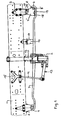
- FIG. 9 There is a vehicle, z. As trucks or buses, a Section of a part of the chassis forming frame side member 1 shown, on which a rigid axle with its axle body 2 is sprung articulated and fixed. This purpose is served by either a single spring leaf or a leaf spring package existing leaf spring 3, which is fastened with its front spring eye 4 on a frame-fixed front bearing block 5 and with its rear spring eye 6 on a rocker 7, where the lower bearing 8, hinged and this rocker 7 is suspended on a rear frame fixed bearing block 9 flying. About the upper bearing point 10 on the rocker 7 whose connection to the bearing block 9 is made.
- a shock absorber 11 which is articulated at the top on a frame-fixed bearing block 12 and at the bottom of the axle 2, and a U-shaped stabilizer 13, with its transverse leg on the axle body 2 and with its two U-shaped stabilizer. Legs is hinged to one holding rod 14, which is suspended with its upper end to a frame-fixed block 15. 16 with a stop buffer is designated, which is fastened on top of the leaf spring 3 and in cooperation with a frame-fixed stop surface 17, the Einfederungsweg of the frame 1 with respect to the axle beam 2 limited.
- a device that could be effective after a break of the leaf spring 3 in the region of its front spring eye 4 has not been provided in this known axle suspension.
- the invention provides a corresponding remedy, as described below.
- a spring catch device is provided in the region of the rear linkage of the leaf spring 3, which then becomes effective when the leaf spring 3 breaks in its front attachment region 4.
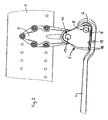
- This spring catching device consists of a relative to the aforementioned known modified, specially designed rocker 7 'and at this (seen in the direction of front leaf spring mounting point 4) spaced before the lower bearing 8 arranged stop 18th
- This stop 18 comes - regardless of its case by case different design and arrangement of the rocker 7 '- after a front breakage of the leaf spring 3 and a displacement thereof backwards due to the concomitant pivoting of the rocker 7' at the top 19 of the leaf spring 3 to the plant , whereby their further displacement is blocked to the rear - see Fig. 2, there the dashed line.
- the stop 18 With intact leaf spring 3, however, the stop 18 remains in each compression state of the frame 1 with respect to the axle body 2 of the rigid axle a more or less large Distance from the leaf spring top 19 spaced - see Fig. 2, where the representation with solid lines.
- the lower holes 24, 25 are used in the region of the lower bearing 8 for the passage of a bearing screw 8 'for the attachment of the rear spring eye 6 of the leaf spring third
- Both plates 20, 21 of the rocker 7 ' have front, inwardly toward each other to angled ends 30, 31, the lower edges of which form the stop 18 and extend at least partially parallel to the upper side 19 of the leaf spring 3.
- Both plates 20, 21 are preferably made of steel or other sheet metal by punching and bending.
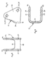
- the rocker 7 ' is formed by a punched-bent part, which is U-shaped, preferably made of steel or another sheet metal, as seen from above.
- the side walls 32, 33 are the same as in the plates 20, 21 of the first embodiment aligned upper holes 22, 23 and spaced therefrom lower holes 24, 25 given.
- the rocker 7 'of FIG. 6 to 8 comes in mounting position with their side walls 32, 33 on the contact surfaces 26, 27 of the bearing block 9 to the plant and is at this same as in the first embodiment via an upper holes 22, 23 and the transverse bore 28 in the bearing block 9 penetrating bearing screw 29 mounted on the bearing block 9 swinging.
- the holes 24, 25 are also used here as in the case of Fig. 1 to 5 for implementation
- the transverse web 34 of the rocker 7 'according to FIG. 6 to 8 a lower edge, which forms the stop 18 and preferably for Top 19 of the leaf spring 3 extends in parallel.
Landscapes
- Engineering & Computer Science (AREA)
- Mechanical Engineering (AREA)
- Vehicle Body Suspensions (AREA)
- Body Structure For Vehicles (AREA)
Claims (5)
- Suspension amortie d'un essieu rigide de cadre de châssis d'un véhicule, en particulier d'un camion ou d'un car de tourisme, le corps d'essieu (2) étant fixé dans la partie inférieure à un ressort à lame (3), qui est articulé à l'avant avec un support de palier (5) fixé au cadre et à l'arrière à un palier inférieur (8) d'une bielle oscillante (7'), qui est elle-même articulée avec un support de palier (9) fixé au cadre par l'intermédiaire d'un palier supérieur (10), caractérisée en ce qu'un dispositif d'arrêt à ressort est prévu et se compose d'une bielle oscillante (7') de conception particulière et d'une butée (18) située à une certaine distance de cette bielle oscillante (7') devant le palier inférieur (8), qui prend appui contre la face supérieure (19) du ressort à lame après une rupture du ressort à lame (3) dans sa zone de fixation avant (4) et un décalage de celui-ci vers l'arrière suite au pivotement de la bielle oscillante (7') qui en résulte et bloque ainsi le prolongement de son décalage vers l'arrière, mais qu'une distance plus ou moins grande soit conservée entre le corps d'essieu (2) de l'essieu rigide et la face supérieure du ressort à lame (19) dans tous les états de débattement du cadre (1) tandis que le ressort à lame (3) reste intact.
- Suspension d'essieu rigide selon la revendication 1, caractérisée en ce que la bielle oscillante (7') se compose de deux plaques (20, 21) dotées d'alésages supérieurs (22, 23) alignés et d'alésages inférieurs (24, 25) situés à une certaine distance des premiers, que l'une des plaques (20, 21) est logée de manière oscillante sur le support de palier (9) contre une surface d'appui intérieure (26) du support de palier (9) et l'autre plaque est logée de manière oscillante sur le support de palier contre une surface d'appui extérieure (27) du support d'appui (9) par l'intermédiaire d'une vis de palier (29) traversant le support de palier (9) par les alésages supérieurs (22, 23) et un alésage transversal (28), que l'orifice arrière (6) du ressort à lame (3) est articulé avec la bielle oscillante (7') à l'aide d'une vis de palier (8) traversant également les alésages (24, 25) dans les plaques (20, 21), et que les deux plaques (20, 21) de la bielle oscillante (7') présentent des extrémités avant (30, 31) coudées vers l'intérieur et l'une vers l'autre, dont les faces inférieures constituent la butée (18).
- Suspension d'essieu rigide selon la revendication 1, caractérisée en ce que la bielle oscillante (7') est constituée d'une pièce découpée et pliée en forme de U - vue du haut - dont les deux faces latérales parallèles (32, 33) sont reliées par un montant transversal (34), que cette bielle oscillante (7') s'appuie contre une surface d'appui extérieure et intérieure (26, 27) du support de palier (9) avec ses faces latérales (32, 33) et est logée de manière oscillante sur le support d'appui (9) au moyen d'une vis de palier (29) traversant les alésages supérieurs (22, 23) et un alésage transversal (28) dans le support de palier, que l'orifice arrière (6) du ressort à lame (3) est articulé avec la bielle oscillante (7') au moyen d'une vis de palier (8) traversant également les alésages inférieurs (24, 25) dans les faces latérales (32, 33) de la bielle oscillante (7'), et que la face inférieure du montant transversal (34) de la bielle oscillante (7') constitue la butée (18).
- Suspension d'essieu rigide selon la revendication 2, caractérisée en ce que les deux plaques (20, 21) de la bielle oscillante (7') se composent de préférence de pièces découpées et pliées en tôle d'acier ou d'un autre métal.
- Suspension d'essieu rigide selon la revendication 3, caractérisée en ce que la bielle oscillante en forme de U (7') se compose de préférence d'une seule pièce découpée et pliée en tôle d'acier ou d'un autre métal.
Priority Applications (1)
| Application Number | Priority Date | Filing Date | Title |
|---|---|---|---|
| AT05004639T ATE336394T1 (de) | 2004-03-05 | 2005-03-03 | Gefederte aufhängung einer starrachse am fahrgestell-rahmen eines fahrzeuges, insbesondere lastkraftwagens oder omnibusses |
Applications Claiming Priority (2)
| Application Number | Priority Date | Filing Date | Title |
|---|---|---|---|
| AT3752004 | 2004-03-05 | ||
| AT0037504A AT413971B (de) | 2004-03-05 | 2004-03-05 | Gefederte aufhängung einer starrachse am fahrgestell-rahmen eines fahrzeugs, insbesondere lastkraftwagens oder omnibusses |
Publications (2)
| Publication Number | Publication Date |
|---|---|
| EP1571013A1 EP1571013A1 (fr) | 2005-09-07 |
| EP1571013B1 true EP1571013B1 (fr) | 2006-08-16 |
Family
ID=34744103
Family Applications (1)
| Application Number | Title | Priority Date | Filing Date |
|---|---|---|---|
| EP05004639A Active EP1571013B1 (fr) | 2004-03-05 | 2005-03-03 | Suspension à ressort d'un essieu rigide pour chassis d'un véhicule, notamment d'un camion ou un autobus |
Country Status (3)
| Country | Link |
|---|---|
| EP (1) | EP1571013B1 (fr) |
| AT (2) | AT413971B (fr) |
| DE (1) | DE502005000056D1 (fr) |
Families Citing this family (3)
| Publication number | Priority date | Publication date | Assignee | Title |
|---|---|---|---|---|
| AT503614B1 (de) * | 2006-02-27 | 2008-07-15 | Man Nutzfahrzeuge Oesterreich | Anschlag zur begrenzung des s-schlags einer blattfeder |
| JP6453617B2 (ja) * | 2014-11-11 | 2019-01-16 | 豊生ブレーキ工業株式会社 | 車両用リーフスプリングのシャックルの製造方法 |
| CN110549807A (zh) * | 2019-08-28 | 2019-12-10 | 东风商用车有限公司 | 一种前钢板弹簧悬架系统 |
Family Cites Families (10)
| Publication number | Priority date | Publication date | Assignee | Title |
|---|---|---|---|---|
| US1350110A (en) * | 1920-08-17 | Combined shock-absorbeb | ||
| US1190966A (en) * | 1915-11-30 | 1916-07-11 | Frank N Sprague | Shackle for the springs of automobiles and other vehicles. |
| FR569371A (fr) * | 1923-08-14 | 1924-04-11 | Perfectionnements au montage des ressorts de véhicules | |
| US2802663A (en) * | 1956-04-05 | 1957-08-13 | Albert H Hovind | Spring suspension |
| US3030101A (en) * | 1959-02-12 | 1962-04-17 | Lester A Mcintosh | Spring shackle |
| FR1357979A (fr) * | 1963-05-21 | 1964-04-10 | Daimler Benz Ag | Ressort lamellaire longitudinal pour voitures automobiles |
| GB1202482A (en) * | 1968-01-16 | 1970-08-19 | Ford Motor Co | Motor vehicle leaf spring assembly |
| WO1988002315A1 (fr) * | 1986-10-04 | 1988-04-07 | Gkn Technology Limited | Suspension pour vehicule |
| US4872653A (en) * | 1988-04-11 | 1989-10-10 | Chuchua Brian N | Shackle for use in limiting the movement of an end of a leaf spring in a wheeled vehicle |
| US4877653A (en) | 1988-07-12 | 1989-10-31 | Hoechst Celanese Corporation | Process for insolublizing solvent soluble polyimide compositions |
-
2004
- 2004-03-05 AT AT0037504A patent/AT413971B/de not_active IP Right Cessation
-
2005
- 2005-03-03 DE DE502005000056T patent/DE502005000056D1/de active Active
- 2005-03-03 AT AT05004639T patent/ATE336394T1/de active
- 2005-03-03 EP EP05004639A patent/EP1571013B1/fr active Active
Also Published As
| Publication number | Publication date |
|---|---|
| ATA3752004A (de) | 2005-11-15 |
| DE502005000056D1 (de) | 2006-09-28 |
| EP1571013A1 (fr) | 2005-09-07 |
| ATE336394T1 (de) | 2006-09-15 |
| AT413971B (de) | 2006-07-15 |
Similar Documents
| Publication | Publication Date | Title |
|---|---|---|
| DE69931983T2 (de) | Stabilisator | |
| DE19536460B4 (de) | Teilrahmen für ein Fahrzeug | |
| DE102010036681B4 (de) | Lenkerarm eines Mehrlenkeraufhängungssystems eines Fahrzeuges | |
| DE102008061833A1 (de) | Querlenker eines Kraftfahrzeuges | |
| DE19605283B4 (de) | Längslenkeraufhängung für Fahrzeuge | |
| DE10221346C1 (de) | Anbindung für ein Fahrerhaus | |
| EP1574366B1 (fr) | Suspension d'essieu et plaque de ressort pour la fixation de l'essieu | |
| DE19812679B4 (de) | Versteifungsanordnung für eine Unterbaugruppe eines Kraftfahrzeugs | |
| EP1616780B1 (fr) | Suspension pour une roue directionnelle d'un véhicule | |
| DE102006044402A1 (de) | Achsaufhängung für eine längslenkergeführte Fahrzeugachse | |
| EP3612748B1 (fr) | Lame ressort pour un ressort à lame | |
| EP1571013B1 (fr) | Suspension à ressort d'un essieu rigide pour chassis d'un véhicule, notamment d'un camion ou un autobus | |
| EP1967394B1 (fr) | Dispositif d'arrêt à ressort | |
| DE102016006848A1 (de) | Achsträger für ein mehrspuriges Kraftfahrzeug | |
| DE4427172A1 (de) | Radaufhängung, insbesondere Hinterachsaufhängung für Nutzfahrzeuge | |
| EP3330110A1 (fr) | Support de palier permettant de fixer un bras oscillant longitudinal à essieux rigides pourvu de composant d'appui influençant le cas de charge de fonctionnement | |
| EP1500530B1 (fr) | Suspension d'essieu rigide pour véhicules avec capture de resort | |
| AT501922B1 (de) | Nutzfahrzeug, insbesondere lastkraftwagen, mit spezieller aufhängung und lenkung zweier benachbarter vorderachsen | |
| WO2013072152A1 (fr) | Essieu rigide à suspension pneumatique | |
| DE202007015877U1 (de) | Unterfahrschutzvorrichtung | |
| DE102005032610B4 (de) | Blattfederaufhängung für Nutzfahrzeuge | |
| DE19849474B4 (de) | Aufhängung einer Hinterachse eines Kraftfahrzeuges | |
| EP0502311B1 (fr) | Essieu à roues directrices et à suspension pneumatique pour véhicule à moteur | |
| DE4107305C2 (de) | Luftgefederte, lenkbare Räder tragende Achse eines Kraftfahrzeuges | |
| DE102017204770B4 (de) | Radaufhängung |
Legal Events
| Date | Code | Title | Description |
|---|---|---|---|
| PUAI | Public reference made under article 153(3) epc to a published international application that has entered the european phase |
Free format text: ORIGINAL CODE: 0009012 |
|
| 17P | Request for examination filed |
Effective date: 20050525 |
|
| AK | Designated contracting states |
Kind code of ref document: A1 Designated state(s): AT BE BG CH CY CZ DE DK EE ES FI FR GB GR HU IE IS IT LI LT LU MC NL PL PT RO SE SI SK TR |
|
| AX | Request for extension of the european patent |
Extension state: AL BA HR LV MK YU |
|
| GRAP | Despatch of communication of intention to grant a patent |
Free format text: ORIGINAL CODE: EPIDOSNIGR1 |
|
| AKX | Designation fees paid |
Designated state(s): AT DE FR IT NL SE |
|
| GRAS | Grant fee paid |
Free format text: ORIGINAL CODE: EPIDOSNIGR3 |
|
| GRAA | (expected) grant |
Free format text: ORIGINAL CODE: 0009210 |
|
| RIN1 | Information on inventor provided before grant (corrected) |
Inventor name: STEINER, ARMIN Inventor name: WAGNER, JOACHIM Inventor name: MEKINA, MARKUS Inventor name: KEPPEL, MANFRED |
|
| AK | Designated contracting states |
Kind code of ref document: B1 Designated state(s): AT DE FR IT NL SE |
|
| PG25 | Lapsed in a contracting state [announced via postgrant information from national office to epo] |
Ref country code: IT Free format text: LAPSE BECAUSE OF FAILURE TO SUBMIT A TRANSLATION OF THE DESCRIPTION OR TO PAY THE FEE WITHIN THE PRESCRIBED TIME-LIMIT;WARNING: LAPSES OF ITALIAN PATENTS WITH EFFECTIVE DATE BEFORE 2007 MAY HAVE OCCURRED AT ANY TIME BEFORE 2007. THE CORRECT EFFECTIVE DATE MAY BE DIFFERENT FROM THE ONE RECORDED. Effective date: 20060816 |
|
| REF | Corresponds to: |
Ref document number: 502005000056 Country of ref document: DE Date of ref document: 20060928 Kind code of ref document: P |
|
| REG | Reference to a national code |
Ref country code: SE Ref legal event code: TRGR |
|
| ET | Fr: translation filed | ||
| PLBE | No opposition filed within time limit |
Free format text: ORIGINAL CODE: 0009261 |
|
| STAA | Information on the status of an ep patent application or granted ep patent |
Free format text: STATUS: NO OPPOSITION FILED WITHIN TIME LIMIT |
|
| 26N | No opposition filed |
Effective date: 20070518 |
|
| PGRI | Patent reinstated in contracting state [announced from national office to epo] |
Ref country code: IT Effective date: 20090501 |
|
| REG | Reference to a national code |
Ref country code: NL Ref legal event code: TD Effective date: 20120223 |
|
| REG | Reference to a national code |
Ref country code: DE Ref legal event code: R081 Ref document number: 502005000056 Country of ref document: DE Owner name: MAN TRUCK & BUS OESTERREICH AG, AT Free format text: FORMER OWNER: MAN NUTZFAHRZEUGE OESTERREICH AG, STEYR, AT Effective date: 20120125 |
|
| REG | Reference to a national code |
Ref country code: FR Ref legal event code: CD Owner name: MAN TRUCK & BUS OSTERREICH AG Effective date: 20120314 |
|
| REG | Reference to a national code |
Ref country code: AT Ref legal event code: HC Ref document number: 336394 Country of ref document: AT Kind code of ref document: T Owner name: MAN TRUCK & BUS OESTERREICH AG, AT Effective date: 20120530 |
|
| REG | Reference to a national code |
Ref country code: FR Ref legal event code: PLFP Year of fee payment: 12 |
|
| PG25 | Lapsed in a contracting state [announced via postgrant information from national office to epo] |
Ref country code: IT Free format text: LAPSE BECAUSE OF FAILURE TO SUBMIT A TRANSLATION OF THE DESCRIPTION OR TO PAY THE FEE WITHIN THE PRESCRIBED TIME-LIMIT Effective date: 20160303 |
|
| REG | Reference to a national code |
Ref country code: FR Ref legal event code: PLFP Year of fee payment: 13 |
|
| PG25 | Lapsed in a contracting state [announced via postgrant information from national office to epo] |
Ref country code: IT Free format text: LAPSE BECAUSE OF FAILURE TO SUBMIT A TRANSLATION OF THE DESCRIPTION OR TO PAY THE FEE WITHIN THE PRESCRIBED TIME-LIMIT Effective date: 20160303 |
|
| PGRI | Patent reinstated in contracting state [announced from national office to epo] |
Ref country code: IT Effective date: 20170710 |
|
| REG | Reference to a national code |
Ref country code: FR Ref legal event code: PLFP Year of fee payment: 14 |
|
| REG | Reference to a national code |
Ref country code: DE Ref legal event code: R081 Ref document number: 502005000056 Country of ref document: DE Owner name: MAN TRUCK & BUS SE, DE Free format text: FORMER OWNER: MAN TRUCK & BUS OESTERREICH AG, STEYR, AT |
|
| REG | Reference to a national code |
Ref country code: AT Ref legal event code: PC Ref document number: 336394 Country of ref document: AT Kind code of ref document: T Owner name: MAN TRUCK & BUS SE, DE Effective date: 20211123 |
|
| PGFP | Annual fee paid to national office [announced via postgrant information from national office to epo] |
Ref country code: FR Payment date: 20230323 Year of fee payment: 19 |
|
| PGFP | Annual fee paid to national office [announced via postgrant information from national office to epo] |
Ref country code: SE Payment date: 20230317 Year of fee payment: 19 Ref country code: IT Payment date: 20230321 Year of fee payment: 19 |
|
| REG | Reference to a national code |
Ref country code: NL Ref legal event code: PD Owner name: MAN TRUCK & BUS OESTERREICH GESMBH; AT Free format text: DETAILS ASSIGNMENT: CHANGE OF OWNER(S), ASSIGNMENT; FORMER OWNER NAME: MAN TRUCK & BUS OESTERREICH GESMBH Effective date: 20231031 |
|
| PGFP | Annual fee paid to national office [announced via postgrant information from national office to epo] |
Ref country code: NL Payment date: 20240326 Year of fee payment: 20 |
|
| PGFP | Annual fee paid to national office [announced via postgrant information from national office to epo] |
Ref country code: AT Payment date: 20240319 Year of fee payment: 20 |
|
| PGFP | Annual fee paid to national office [announced via postgrant information from national office to epo] |
Ref country code: DE Payment date: 20240328 Year of fee payment: 20 |