EP1569805B1 - Dispositif de marquage pour coder des pieces metalliques avec des codes a matrice en deux dimensions - Google Patents
Dispositif de marquage pour coder des pieces metalliques avec des codes a matrice en deux dimensions Download PDFInfo
- Publication number
- EP1569805B1 EP1569805B1 EP03769490A EP03769490A EP1569805B1 EP 1569805 B1 EP1569805 B1 EP 1569805B1 EP 03769490 A EP03769490 A EP 03769490A EP 03769490 A EP03769490 A EP 03769490A EP 1569805 B1 EP1569805 B1 EP 1569805B1
- Authority
- EP
- European Patent Office
- Prior art keywords
- marking device
- current
- marking
- workpiece
- control
- Prior art date
- Legal status (The legal status is an assumption and is not a legal conclusion. Google has not performed a legal analysis and makes no representation as to the accuracy of the status listed.)
- Expired - Lifetime
Links
Images

Classifications
-
- B—PERFORMING OPERATIONS; TRANSPORTING
- B21—MECHANICAL METAL-WORKING WITHOUT ESSENTIALLY REMOVING MATERIAL; PUNCHING METAL
- B21C—MANUFACTURE OF METAL SHEETS, WIRE, RODS, TUBES, PROFILES OR LIKE SEMI-MANUFACTURED PRODUCTS OTHERWISE THAN BY ROLLING; AUXILIARY OPERATIONS USED IN CONNECTION WITH METAL-WORKING WITHOUT ESSENTIALLY REMOVING MATERIAL
- B21C51/00—Measuring, gauging, indicating, counting, or marking devices specially adapted for use in the production or manipulation of material in accordance with subclasses B21B - B21F
- B21C51/005—Marking devices
-
- B—PERFORMING OPERATIONS; TRANSPORTING
- B44—DECORATIVE ARTS
- B44B—MACHINES, APPARATUS OR TOOLS FOR ARTISTIC WORK, e.g. FOR SCULPTURING, GUILLOCHING, CARVING, BRANDING, INLAYING
- B44B5/00—Machines or apparatus for embossing decorations or marks, e.g. embossing coins
- B44B5/0061—Machines or apparatus for embossing decorations or marks, e.g. embossing coins characterised by the power drive
- B44B5/0066—Machines or apparatus for embossing decorations or marks, e.g. embossing coins characterised by the power drive producing a vibratory motion
Definitions
- the invention relates to a marking device for coding metallic workpieces with two-dimensional matrix codes, in which the information is present as recessed dots in a square or rectangular arrangement. The presence or absence of these embossed dots at the respective grid locations represents the binary coded information.
- the precision with which the embossed dots are applied is of great importance.
- the exact shape, size and depth of the dots are important quality features. This is directly related to the type of reading technique such embossed or embossed codings using CCD cameras. Top or side illumination must create a bright-dark contrast from the respective well via corresponding reflections, which is much more difficult than with in-plane printed black and white areas for which the code was originally designed. A different shape or size of the individual wells can easily generate a reflection or even undesirably do not produce, which can lead to an undesired infortmation-falsification. In the aerospace industry For critical, highly loaded components, even more stringent requirements are added, which aim at avoiding the reduction of mechanical strength due to notch effect.
- the invention has for its object to improve the movement of a driven by an electromagnet assembly impact tool so that formed as depressions Markings can be formed with much higher precision.
- the current flow through the electromagnet arrangement for the acceleration phase and the subsequent movement phase of the impact tool can be set differently.
- this leads to a rapid acceleration, wherein after switching over to the lower current of the movement phase, the impact tool is moved in a defined manner against the workpiece.
- This leads to a large uniformity and reproducibility of the depression formed. Due to the substantially uniform movement due to the lower current during the movement phase, a greater tolerance is allowed for the distance of the marking device to the workpiece. In the known devices an increasing distance leads due to the longer acceleration phase to a more pronounced depression.
- the lower current during the motion phase also avoids an uncontrollable, purely ballistic "free-flying phase" of the impact tool until it hits the workpiece surface, which would occur if the current were switched off prior to hitting the workpiece, which in turn larger tolerances of the markers would be connected.
- this reversal takes place in a simple execution by means of a time control.
- this reversal can also be position-dependent, for which purpose a position measuring device is provided for controlling the changeover in at least one predeterminable position.
- this position measuring device can be a simple position sensor in a certain position or else an end position sensor which responds after a certain distance covered during the striking movement.
- the position measurement can be used advantageously for detecting the length of the entire movement distance of the impact tool, ie for measuring the distance to the workpiece.
- the corresponding measured value can then also be used as a working parameter for determining the current strengths and times or positions.
- means for eliminating the current upon reaching the impact position are preferably provided.
- the current increase of the supply current for the electromagnet arrangement with a current sensor can be detected for this purpose, wherein this increase in current occurs when the movement of the magnet armature, ie the impact tool, is stopped and no inductance change takes place in the coil of the solenoid assembly more.
- means for generating a braking current before reaching the rest position during the return movement of the impact tool are provided in an advantageous manner. These means may be time- and / or position-controlled, and the current value is chosen so that the impact tool is braked as far as possible to the rest position to zero speed. This ensures a very fast work cycle.
- the control device advantageously contains a microcomputer with a memory device in which the working parameters are stored, in particular current intensities, times, path parameters, workpiece properties, temperatures and the like.
- the working parameters are expediently contained as tables and can be selected and / or changed as a function of the respective marking process. While some parameters have to be entered, taking into account, for example, the workpiece characteristics of the workpiece to be marked, other parameters may be detected by sensors, such as the temperature, and still others are measured in the manner already indicated, for example the position of the impact tool along the entire movement path.
- control device is connected between a main controller for the marking device and the electromagnet arrangement and is preferably designed as a separate module which, for example, can also be subsequently retrofitted.
- the various current values can be controlled or regulated depending on the position or time during the entire movement distance.
- FIG. 1 in a schematic diagram schematically illustrated marking head 10 has an electromagnetic coil 11, which for generating the impact movement of an example as Hard metal needle trained impact tool 12 is formed.
- the impact tool 12 is connected to a magnet armature 9, which is movable against the force of a return spring 13 to a workpiece 14.
- another known return device may be provided, for example, a pneumatic, hydraulic or electromagnetic acting return device.
- the marking head 10 is movable by means of an adjusting device, not shown, in the x- and y-direction of a plane which is arranged parallel to the plane of the workpiece 14. As a result, the marking head 10 can approach each position of the workpiece 14.
- the marking head 10 is used for introducing coding points formed as depressions in the metallic workpiece 14. These coding points form a two-dimensional matrix code which represents binary-coded information. After starting the desired grid point, the impact tool 12 is moved against the workpiece 14 by actuation of the electromagnetic coil 11 to produce the desired code recess.
- the basic control of the marking head 10 is effected by a main controller 15, by means of which the position of the marking head 10 can be controlled by means of the adjusting device, not shown, and the triggering of the movement of the striking tool 12.
- a control device 16 is connected, through which the exact movement of the impact tool 12 is controlled.
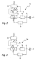
- a first embodiment of this control device 16 is shown in FIG figure 2 and a second embodiment in FIG. 3 shown.
- the position signal S of a position measuring device 20 is supplied to detect the respective position of the striking tool 12.
- This position measuring device is, for example, at an inductive displacement measuring system, which in FIG. 1 is arranged outside of the electromagnetic coil 11, but may also be integrated in the magnetic drive.
- this displacement measuring signal S is compared during the striking movement with a stored switching value S 0 , and upon reaching the same, a switchover takes place from an initially high current value I 1 to a smaller current value I 2 .
- the initially high current value I 1 is used for rapid acceleration of the impact tool 12 during an acceleration phase, wherein the smaller current value I 2 is selected so that the impact tool is guided to the workpiece after this acceleration phase with the greatest possible speed.
- the return to the lower current value I 2 can of course also take place in several stages.
- a current increase of the supply current for the electromagnetic coil 11 since at the end of the movement of the armature 9, no inductance change of the electromagnetic coil 11 takes place more.
- This increase in current is detected by a current sensor 21 and fed to an evaluation stage 22 for the current increase, which may for example contain a differentiating stage. If this current increase is detected, then takes place by a reset signal R, a shutdown of the current for the electromagnetic coil eleventh
- the operating parameters for the adjustment of the positions and currents are stored.
- Such operating parameters are, for example, currents, times, path parameters, workpiece properties, temperatures and the like; which are stored as tables. Based on these tables, the currents I 1 and I 2 and the positions S 0 and S 1 are then specified, for example calculated. These are parameters that influence the movement of the impact tool 12.
- the temperature of the marking head 10 or the electromagnetic coil 11 can be measured, for example, in a manner not shown.
- Other working parameters, such as the material properties of the workpiece 14 can be stored by means of an input device, not shown.
- An important parameter is still the working stroke, ie the length of the working movement until it hits the workpiece 14.
- the distance can be detected by means of the position measuring device 20. The measurement takes place until it hits the workpiece 14, which is signaled by the evaluation stage 22.
- the currently used control parameters for the relevant workpiece 14 are then individually changed so that the striking energy effective for marking corresponds again to the desired value.
- this distance measurement can be applied to the position of the workpiece surface to be marked relative to the mounting height of the marking head 10.
- the height of the marking head 10 is made adjustable with a third NC axis.
- the impact tool 12 is fully extended with sufficient to overcome the restoring force, set by the current control stage 17 current and then driven the marking head 10 from a known, higher position against the workpiece surface.
- the impact tool 12 Once the impact tool 12 occurs on the surface, it is retracted until the already existing distance sensor 20 in the marking head 10 emits a signal. Since the way from fully extended impact tool 12 is known to the switching point of the sensor, the position of the workpiece surface can be accurately determined from the entire track and used for precise adjustment of the desired distance of the impact tool 12 from the workpiece 14. Also by this method, negative-working workpiece tolerances are eliminated.
- the control device can therefore increase the acceleration current I 1 for the first lifting movement. This increase can also be set via stored tables.
- the current control stage 17 can only control the current values I 1 and I 2 or further current values, or it can be designed as a current regulation stage.
- a simple position sensor may be provided, which merely specifies a switching signal at a fixed position S 0 or S 1 .
- This may be, for example, an end position sensor which emits a signal when the rest position has been left by a certain distance S 0 or when the armature 9 has approached by a certain distance S 1 in return movement.
- control device 16 is realized for example as a microcomputer or microcontroller.
- the memory device 23 is then a non-volatile main memory of the microcontroller.
- FIG. 3 a modified controller 16a is shown. Same or equivalent components or elements are provided with the same reference numerals and not described again in detail.
- a time specification stage 24 occurs in the second exemplary embodiment. This is triggered by a signal of the main controller 15. After a time t 0 has elapsed, the switchover takes place from the higher current value I 1 for the acceleration phase to the lower current value I 2 for the movement phase. Accordingly, the braking current is switched on during the return movement of the striking tool 12 after a time t 1 .
- the memory device 23 contains the stored values t 0 and t 1 , which are predetermined in accordance with the first embodiment on the basis of the working parameter tables.
- Combinations of the two embodiments can also be implemented for current control and / or regulation, that is to say the adjustment or regulation of the currents takes place partly time-dependent and partly position-dependent.
Landscapes
- Engineering & Computer Science (AREA)
- Mechanical Engineering (AREA)
- Percussive Tools And Related Accessories (AREA)
- Detection And Prevention Of Errors In Transmission (AREA)
- Shaping Metal By Deep-Drawing, Or The Like (AREA)
Claims (14)
- Dispositif de marquage pour coder des pièces d'oeuvre métalliques avec des codes à matrice en deux dimensions, avec un outil de percussion (12), susceptible d'être entraîné au moyen d'un dispositif à électroaimant (11), pour former les cavités de code, le déplacement de travail s'effectuant à l'encontre de la force d'un dispositif de rappel (13), avec un dispositif de réglage, déplaçable dans les deux axes (x, y), perpendiculairement à la direction de percussion (z), pour assurer le positionnement de l'outil de percussion (12) aux positions de code souhaitées, caractérisé par un dispositif de commande (16, 16a) électronique pour le déplacement de l'outil de percussion (12), comprenant des moyens (17) pour l'affectation d'une intensité (I1) plus élevée pour le dispositif à électroaimant (11) pendant une première phase d'accélération de l'outil de percussion (12), et une intensité (I2) plus faible, pendant la phase de déplacement faisant suite, jusqu'à l'impact sur la pièce d'oeuvre (14).
- Dispositif de marquage selon la revendication 1, caractérisé en ce qu'une commande temporelle (24) est prévue pour l'affectation du temps d'accélération.
- Dispositif de marquage selon la revendication 1, caractérisé en ce qu'une commande de position (19) est prévue, pour la commutation de la phase d'accélération à la phase de déplacement faisant suite.
- Dispositif de marquage selon la revendication 3, caractérisé en ce qu'un dispositif de mesure de position (20), en particulier un capteur de position, est prévu pour la commande de la commutation en au moins une position (So) susceptible d'être affectée.
- Dispositif de marquage selon la revendication 4, caractérisé en ce que le dispositif de mesure de position (20) est également réalisé pour la détection de la longueur de l'ensemble de la course de déplacement de l'outil de percussion (12) et/ou de son espacement par rapport à la pièce d'oeuvre (14).
- Dispositif de marquage selon la revendication 5, caractérisé en ce que le dispositif de mesure de position (20) est placé en liaison fonctionnelle avec des moyens pour déterminer l'espacement, soumis à des tolérances, entre la tête de marquage (10) et la surface de pièce d'oeuvre, lors d'un avancement s'effectuant avant le marquage et pour la compensation des paramètres de commande, par le biais d'une correction correspondante.
- Dispositif de marquage selon la revendication 5, caractérisé en ce que le dispositif de mesure de position (20) est placé en liaison fonctionnelle avec des moyens pour déterminer l'espacement, soumis à des tolérances, entre la tête de marquage (10) et la surface de pièce d'oeuvre, lors d'un avancement s'effectuant avant le marquage et pour la compensation des paramètres de commande, par l'intermédiaire d'un dispositif de réglage de hauteur.
- Dispositif de marquage selon l'une des revendications précédentes, caractérisé en ce que l'intensité est commandée ou régulée en fonction de la position, ou en fonction du temps, pendant l'ensemble de la course de déplacement.
- Dispositif de marquage selon l'une des revendications précédentes, caractérisé en ce que des moyens (21, 33) sont prévus, pour la coupure du courant à l'atteinte de la position de percussion.
- Dispositif de marquage selon la revendication 9, caractérisé en ce que les moyens (21, 22) sont réalisés pour l'identification d'une augmentation d'intensité correspondante, à l'atteinte de la position de percussion.
- Dispositif de marquage selon l'une des revendications précédentes, caractérisé en ce que des moyens sont prévus, pour générer un courant de freinage avant atteinte de la position de repos, lors du déplacement de rappel de l'outil de percussion (12).
- Dispositif de marquage selon la revendication 11, caractérisé en ce que les moyens pour générer un courant de freinage sont commandés en fonction du temps et/ou de la position.
- Dispositif de marquage selon l'une des revendications précédentes, caractérisé en ce que le dispositif de commande (16, 16a) est branché entre un contrôleur principal (15) pour le dispositif de marquage et le dispositif à électroaimant (11), et est de préférence réalisé sous forme de module séparé.
- Dispositif de marquage selon l'une des revendications précédentes, caractérisé en ce que des moyens sont prévus, pour augmenter l'intensité maximale (I1) dans la phase d'accélération, lors de la première course de travail.
Applications Claiming Priority (3)
| Application Number | Priority Date | Filing Date | Title |
|---|---|---|---|
| DE10257532A DE10257532A1 (de) | 2002-12-10 | 2002-12-10 | Markiervorrichtung zum Codieren metallischer Werkstücke mit zweidimensionalen Matrix-Codes |
| DE10257532 | 2002-12-10 | ||
| PCT/EP2003/012409 WO2004052660A1 (fr) | 2002-12-10 | 2003-11-06 | Dispositif de marquage pour coder des pieces metalliques avec des codes a matrice en deux dimensions |
Publications (2)
| Publication Number | Publication Date |
|---|---|
| EP1569805A1 EP1569805A1 (fr) | 2005-09-07 |
| EP1569805B1 true EP1569805B1 (fr) | 2010-04-14 |
Family
ID=32336155
Family Applications (1)
| Application Number | Title | Priority Date | Filing Date |
|---|---|---|---|
| EP03769490A Expired - Lifetime EP1569805B1 (fr) | 2002-12-10 | 2003-11-06 | Dispositif de marquage pour coder des pieces metalliques avec des codes a matrice en deux dimensions |
Country Status (6)
| Country | Link |
|---|---|
| US (1) | US7357013B2 (fr) |
| EP (1) | EP1569805B1 (fr) |
| AT (1) | ATE464189T1 (fr) |
| AU (1) | AU2003278177A1 (fr) |
| DE (2) | DE10257532A1 (fr) |
| WO (1) | WO2004052660A1 (fr) |
Cited By (1)
| Publication number | Priority date | Publication date | Assignee | Title |
|---|---|---|---|---|
| CN111659755A (zh) * | 2020-06-15 | 2020-09-15 | 北海智异电子科技有限公司 | 一种冲压模具螺丝孔标点装置 |
Families Citing this family (13)
| Publication number | Priority date | Publication date | Assignee | Title |
|---|---|---|---|---|
| DE10354258B3 (de) * | 2003-11-20 | 2005-08-11 | Borries Markier-Systeme Gmbh | Markiersystem für Werkstücke |
| CN100418781C (zh) * | 2006-05-26 | 2008-09-17 | 杨光 | 探杆式打标机 |
| DE102006052421B4 (de) * | 2006-11-07 | 2009-06-18 | Borries Markier-Systeme Gmbh | Markierkopf für Ritzpräger zum Markieren und Kennzeichnen von Materialoberflächen |
| RU2347681C2 (ru) * | 2007-02-13 | 2009-02-27 | Магомед Хабибович Магомедов | Способ автоматического выставления, регулирования и непрерывного контроля положения инструмента при нанесении изображения на твердые поверхности |
| KR200447537Y1 (ko) * | 2009-09-25 | 2010-02-03 | 제일엠텍(주) | 자력을 이용한 금속용 마킹장치 |
| JP2012234920A (ja) * | 2011-04-28 | 2012-11-29 | Toshiba Corp | 半導体製造装置および半導体装置の製造方法 |
| DE102011054776B4 (de) | 2011-10-25 | 2014-12-31 | Borries Markier-Systeme Gmbh | Markierprägevorrichtung für die Beschriftung auf Holz und Verfahren zum Prägen |
| JP5851813B2 (ja) * | 2011-12-05 | 2016-02-03 | 三菱重工業株式会社 | 板状ワークの湾曲保持装置および湾曲保持方法ならびに湾曲成形方法 |
| DE102015004227A1 (de) | 2015-03-31 | 2016-10-06 | Sigmund Scriba | Verfahren zum Einbringen einer Codierung in ein Werkstück und Stempel zum Einbringen einer Codierung in ein Werkstück |
| CN107234146B (zh) * | 2016-03-28 | 2019-03-15 | 上海飞乐汽车控制系统有限公司 | 自动打点线序检测仪 |
| USD863389S1 (en) * | 2017-11-28 | 2019-10-15 | Red Technology Co., Ltd. | Portable dot peen marking machine |
| US10723005B2 (en) | 2018-03-28 | 2020-07-28 | Black & Decker Inc. | Electric fastener driving tool assembly including a driver home position sensor |
| CN109093054B (zh) * | 2018-06-29 | 2019-12-10 | 合肥巨一智能装备有限公司 | 铝合金车身流钻拧紧设备调试定位方法和激光调试系统 |
Family Cites Families (7)
| Publication number | Priority date | Publication date | Assignee | Title |
|---|---|---|---|---|
| CH172143A (de) | 1934-05-25 | 1934-09-30 | Lustenberger Alfred | Elektrisches Schlagwerkzeug. |
| US5015106A (en) | 1989-09-25 | 1991-05-14 | Telesis Controls Corporation | Marking apparatus with multiple line capability |
| US5316397A (en) * | 1992-07-31 | 1994-05-31 | Telesis Marking Systems, Inc. | Marking apparatus with multiple marking modes |
| US5368400A (en) * | 1993-10-15 | 1994-11-29 | Telesis Marking Systems, Inc. | Marking apparatus with cable drive |
| US5785436A (en) * | 1997-04-09 | 1998-07-28 | Harrison; Michael E. | Data platemarking system |
| WO2001070452A1 (fr) * | 2000-03-20 | 2001-09-27 | Dapra Corporation | Appareil de marquage solidaire d'une machine outil et procede |
| US6835011B2 (en) * | 2003-03-03 | 2004-12-28 | Toshiba Tec Kabushiki Kaisha | Impact dot printing head control apparatus |
-
2002
- 2002-12-10 DE DE10257532A patent/DE10257532A1/de not_active Withdrawn
-
2003
- 2003-11-06 WO PCT/EP2003/012409 patent/WO2004052660A1/fr not_active Ceased
- 2003-11-06 EP EP03769490A patent/EP1569805B1/fr not_active Expired - Lifetime
- 2003-11-06 AT AT03769490T patent/ATE464189T1/de not_active IP Right Cessation
- 2003-11-06 AU AU2003278177A patent/AU2003278177A1/en not_active Abandoned
- 2003-11-06 DE DE50312631T patent/DE50312631D1/de not_active Expired - Lifetime
- 2003-11-06 US US10/537,995 patent/US7357013B2/en not_active Expired - Lifetime
Cited By (1)
| Publication number | Priority date | Publication date | Assignee | Title |
|---|---|---|---|---|
| CN111659755A (zh) * | 2020-06-15 | 2020-09-15 | 北海智异电子科技有限公司 | 一种冲压模具螺丝孔标点装置 |
Also Published As
| Publication number | Publication date |
|---|---|
| EP1569805A1 (fr) | 2005-09-07 |
| WO2004052660A1 (fr) | 2004-06-24 |
| DE10257532A1 (de) | 2004-06-24 |
| US20060075800A1 (en) | 2006-04-13 |
| DE50312631D1 (de) | 2010-05-27 |
| US7357013B2 (en) | 2008-04-15 |
| ATE464189T1 (de) | 2010-04-15 |
| AU2003278177A1 (en) | 2004-06-30 |
Similar Documents
| Publication | Publication Date | Title |
|---|---|---|
| EP1569805B1 (fr) | Dispositif de marquage pour coder des pieces metalliques avec des codes a matrice en deux dimensions | |
| DE3708989C2 (de) | Steuervorrichtung für einen in einem doppeltwirkenden Zylinder verschiebbaren Kolben | |
| DE19518056B4 (de) | Einrichtung zur Steuerung der Ankerbewegung einer elektromagnetischen Schaltanordnung und Verfahren zur Ansteuerung | |
| DE3347491C2 (fr) | ||
| EP1001142B1 (fr) | Procédé de fonctionnement d'un actionneur de soupape à commande électromagnétique | |
| DE3312526C2 (fr) | ||
| EP3111454B1 (fr) | Dispositif comprenant un interrupteur électrique et un actionneur électromagnétique | |
| DE2162018C2 (de) | Einrichtung zur Steuerung der Seitenverstellung von Stopfwerkzeugaggregaten einer Gleisbaumaschine | |
| DE19920181A1 (de) | Verfahren zur Regelung der Ankerauftreffgeschwindigkeit an einem elektromagnetischen Aktuator durch eine kennfeldgestützte Regelung der Bestromung | |
| DE102015003435A1 (de) | Laserbearbeitungsvorrichtung, die dazu fähig ist, bei Erfassung eines Stromausfalls eine Bearbeitungsdüse zurückzuziehen | |
| DE102008011024B4 (de) | Schneidverfahren zum Vermindern eines Schnittschlags und Schneidmaschine mit einem Kurbelantrieb zur Durchführung dieses Verfahrens | |
| DE19849384A1 (de) | Lineare Vorschubantrieb-Einrichtung für Bearbeitungswerkzeuge mit integrierter taktiler Fühleinrichtung für Erst-Positionierungsvorgänge am Werkstück vor Beginn des Bearbeitungsprozesses und integrierter Gewichtsentlastung | |
| DE10207726A1 (de) | Kurzzeit-Lichtbogenschweißsystem und -verfahren | |
| DE3929669C2 (de) | Bolzenanschweißvorrichtung | |
| EP1259351B1 (fr) | Tete de soudage de goujons | |
| DE10138947A1 (de) | Kurzzeit-Lichtbogenschweisssystem und Verfahren zum Kurzzeit-Lichtbogenschweissen | |
| EP0732194A1 (fr) | Procédé et dispositif de mesure et de réglage de la position du coulisseau d'une presse à découper à grande vitesse | |
| EP0632202A1 (fr) | Procédé pour la mise en oeuvre d'un instrument de positionnement ou de préhension ou de serrage actionné par un medium de tension | |
| DE10144256A1 (de) | Kurzzeit-Lichtbogenschweißsystem und -verfahren | |
| EP0408963A2 (fr) | Procédé pour commander le mouvement de l'armature d'aimants de commutation | |
| EP1101015A1 (fr) | Procede de commande d'un actionneur electromagnetique destine a actionner une soupape d'echange des gaz d'un moteur a pistons | |
| DE894067C (de) | Fuehlergesteuerter Nachlaufregler, insbesondere fuer Kopier-werkzeugmaschinen | |
| DE2158813A1 (de) | Vorrichtung zum einstellen eines werkzeugschlittens einer werkzeugmaschine, insbesondere einer drehmaschine | |
| DE3438600C2 (fr) | ||
| EP1462660A1 (fr) | Actionneur hydraulique, méthode pour faire fonctionner un actionneur hydraulique et dispositif de commande associé. |
Legal Events
| Date | Code | Title | Description |
|---|---|---|---|
| PUAI | Public reference made under article 153(3) epc to a published international application that has entered the european phase |
Free format text: ORIGINAL CODE: 0009012 |
|
| 17P | Request for examination filed |
Effective date: 20050602 |
|
| AK | Designated contracting states |
Kind code of ref document: A1 Designated state(s): AT BE BG CH CY CZ DE DK EE ES FI FR GB GR HU IE IT LI LU MC NL PT RO SE SI SK TR |
|
| AX | Request for extension of the european patent |
Extension state: AL LT LV MK |
|
| DAX | Request for extension of the european patent (deleted) | ||
| GRAP | Despatch of communication of intention to grant a patent |
Free format text: ORIGINAL CODE: EPIDOSNIGR1 |
|
| GRAS | Grant fee paid |
Free format text: ORIGINAL CODE: EPIDOSNIGR3 |
|
| GRAA | (expected) grant |
Free format text: ORIGINAL CODE: 0009210 |
|
| AK | Designated contracting states |
Kind code of ref document: B1 Designated state(s): AT BE BG CH CY CZ DE DK EE ES FI FR GB GR HU IE IT LI LU MC NL PT RO SE SI SK TR |
|
| REG | Reference to a national code |
Ref country code: GB Ref legal event code: FG4D Free format text: NOT ENGLISH |
|
| REG | Reference to a national code |
Ref country code: CH Ref legal event code: EP |
|
| REG | Reference to a national code |
Ref country code: IE Ref legal event code: FG4D Free format text: LANGUAGE OF EP DOCUMENT: GERMAN |
|
| REF | Corresponds to: |
Ref document number: 50312631 Country of ref document: DE Date of ref document: 20100527 Kind code of ref document: P |
|
| REG | Reference to a national code |
Ref country code: NL Ref legal event code: VDEP Effective date: 20100414 |
|
| PG25 | Lapsed in a contracting state [announced via postgrant information from national office to epo] |
Ref country code: NL Free format text: LAPSE BECAUSE OF FAILURE TO SUBMIT A TRANSLATION OF THE DESCRIPTION OR TO PAY THE FEE WITHIN THE PRESCRIBED TIME-LIMIT Effective date: 20100414 Ref country code: SE Free format text: LAPSE BECAUSE OF FAILURE TO SUBMIT A TRANSLATION OF THE DESCRIPTION OR TO PAY THE FEE WITHIN THE PRESCRIBED TIME-LIMIT Effective date: 20100414 Ref country code: ES Free format text: LAPSE BECAUSE OF FAILURE TO SUBMIT A TRANSLATION OF THE DESCRIPTION OR TO PAY THE FEE WITHIN THE PRESCRIBED TIME-LIMIT Effective date: 20100725 |
|
| REG | Reference to a national code |
Ref country code: IE Ref legal event code: FD4D |
|
| PG25 | Lapsed in a contracting state [announced via postgrant information from national office to epo] |
Ref country code: SI Free format text: LAPSE BECAUSE OF FAILURE TO SUBMIT A TRANSLATION OF THE DESCRIPTION OR TO PAY THE FEE WITHIN THE PRESCRIBED TIME-LIMIT Effective date: 20100414 Ref country code: FI Free format text: LAPSE BECAUSE OF FAILURE TO SUBMIT A TRANSLATION OF THE DESCRIPTION OR TO PAY THE FEE WITHIN THE PRESCRIBED TIME-LIMIT Effective date: 20100414 |
|
| PG25 | Lapsed in a contracting state [announced via postgrant information from national office to epo] |
Ref country code: GR Free format text: LAPSE BECAUSE OF FAILURE TO SUBMIT A TRANSLATION OF THE DESCRIPTION OR TO PAY THE FEE WITHIN THE PRESCRIBED TIME-LIMIT Effective date: 20100715 Ref country code: CY Free format text: LAPSE BECAUSE OF FAILURE TO SUBMIT A TRANSLATION OF THE DESCRIPTION OR TO PAY THE FEE WITHIN THE PRESCRIBED TIME-LIMIT Effective date: 20100421 |
|
| PG25 | Lapsed in a contracting state [announced via postgrant information from national office to epo] |
Ref country code: IE Free format text: LAPSE BECAUSE OF FAILURE TO SUBMIT A TRANSLATION OF THE DESCRIPTION OR TO PAY THE FEE WITHIN THE PRESCRIBED TIME-LIMIT Effective date: 20100414 Ref country code: PT Free format text: LAPSE BECAUSE OF FAILURE TO SUBMIT A TRANSLATION OF THE DESCRIPTION OR TO PAY THE FEE WITHIN THE PRESCRIBED TIME-LIMIT Effective date: 20100816 Ref country code: DK Free format text: LAPSE BECAUSE OF FAILURE TO SUBMIT A TRANSLATION OF THE DESCRIPTION OR TO PAY THE FEE WITHIN THE PRESCRIBED TIME-LIMIT Effective date: 20100414 Ref country code: EE Free format text: LAPSE BECAUSE OF FAILURE TO SUBMIT A TRANSLATION OF THE DESCRIPTION OR TO PAY THE FEE WITHIN THE PRESCRIBED TIME-LIMIT Effective date: 20100414 |
|
| PLBE | No opposition filed within time limit |
Free format text: ORIGINAL CODE: 0009261 |
|
| STAA | Information on the status of an ep patent application or granted ep patent |
Free format text: STATUS: NO OPPOSITION FILED WITHIN TIME LIMIT |
|
| PG25 | Lapsed in a contracting state [announced via postgrant information from national office to epo] |
Ref country code: CZ Free format text: LAPSE BECAUSE OF FAILURE TO SUBMIT A TRANSLATION OF THE DESCRIPTION OR TO PAY THE FEE WITHIN THE PRESCRIBED TIME-LIMIT Effective date: 20100414 Ref country code: SK Free format text: LAPSE BECAUSE OF FAILURE TO SUBMIT A TRANSLATION OF THE DESCRIPTION OR TO PAY THE FEE WITHIN THE PRESCRIBED TIME-LIMIT Effective date: 20100414 Ref country code: RO Free format text: LAPSE BECAUSE OF FAILURE TO SUBMIT A TRANSLATION OF THE DESCRIPTION OR TO PAY THE FEE WITHIN THE PRESCRIBED TIME-LIMIT Effective date: 20100414 |
|
| 26N | No opposition filed |
Effective date: 20110117 |
|
| PG25 | Lapsed in a contracting state [announced via postgrant information from national office to epo] |
Ref country code: IT Free format text: LAPSE BECAUSE OF FAILURE TO SUBMIT A TRANSLATION OF THE DESCRIPTION OR TO PAY THE FEE WITHIN THE PRESCRIBED TIME-LIMIT Effective date: 20100414 |
|
| BERE | Be: lapsed |
Owner name: BORRIES MARKIER-SYSTEME G.M.B.H. Effective date: 20101130 |
|
| PG25 | Lapsed in a contracting state [announced via postgrant information from national office to epo] |
Ref country code: MC Free format text: LAPSE BECAUSE OF NON-PAYMENT OF DUE FEES Effective date: 20101130 |
|
| PG25 | Lapsed in a contracting state [announced via postgrant information from national office to epo] |
Ref country code: BE Free format text: LAPSE BECAUSE OF NON-PAYMENT OF DUE FEES Effective date: 20101130 |
|
| REG | Reference to a national code |
Ref country code: AT Ref legal event code: MM01 Ref document number: 464189 Country of ref document: AT Kind code of ref document: T Effective date: 20101106 |
|
| PG25 | Lapsed in a contracting state [announced via postgrant information from national office to epo] |
Ref country code: AT Free format text: LAPSE BECAUSE OF NON-PAYMENT OF DUE FEES Effective date: 20101106 |
|
| PG25 | Lapsed in a contracting state [announced via postgrant information from national office to epo] |
Ref country code: HU Free format text: LAPSE BECAUSE OF FAILURE TO SUBMIT A TRANSLATION OF THE DESCRIPTION OR TO PAY THE FEE WITHIN THE PRESCRIBED TIME-LIMIT Effective date: 20101015 Ref country code: LU Free format text: LAPSE BECAUSE OF NON-PAYMENT OF DUE FEES Effective date: 20101106 Ref country code: BG Free format text: LAPSE BECAUSE OF FAILURE TO SUBMIT A TRANSLATION OF THE DESCRIPTION OR TO PAY THE FEE WITHIN THE PRESCRIBED TIME-LIMIT Effective date: 20100414 |
|
| PG25 | Lapsed in a contracting state [announced via postgrant information from national office to epo] |
Ref country code: TR Free format text: LAPSE BECAUSE OF FAILURE TO SUBMIT A TRANSLATION OF THE DESCRIPTION OR TO PAY THE FEE WITHIN THE PRESCRIBED TIME-LIMIT Effective date: 20100414 |
|
| PG25 | Lapsed in a contracting state [announced via postgrant information from national office to epo] |
Ref country code: BG Free format text: LAPSE BECAUSE OF FAILURE TO SUBMIT A TRANSLATION OF THE DESCRIPTION OR TO PAY THE FEE WITHIN THE PRESCRIBED TIME-LIMIT Effective date: 20100714 |
|
| PGFP | Annual fee paid to national office [announced via postgrant information from national office to epo] |
Ref country code: CH Payment date: 20131128 Year of fee payment: 11 |
|
| REG | Reference to a national code |
Ref country code: CH Ref legal event code: PL |
|
| PG25 | Lapsed in a contracting state [announced via postgrant information from national office to epo] |
Ref country code: LI Free format text: LAPSE BECAUSE OF NON-PAYMENT OF DUE FEES Effective date: 20141130 Ref country code: CH Free format text: LAPSE BECAUSE OF NON-PAYMENT OF DUE FEES Effective date: 20141130 |
|
| REG | Reference to a national code |
Ref country code: FR Ref legal event code: PLFP Year of fee payment: 13 |
|
| REG | Reference to a national code |
Ref country code: FR Ref legal event code: PLFP Year of fee payment: 14 |
|
| PGFP | Annual fee paid to national office [announced via postgrant information from national office to epo] |
Ref country code: GB Payment date: 20161124 Year of fee payment: 14 Ref country code: DE Payment date: 20161128 Year of fee payment: 14 Ref country code: FR Payment date: 20161124 Year of fee payment: 14 |
|
| REG | Reference to a national code |
Ref country code: DE Ref legal event code: R119 Ref document number: 50312631 Country of ref document: DE |
|
| GBPC | Gb: european patent ceased through non-payment of renewal fee |
Effective date: 20171106 |
|
| REG | Reference to a national code |
Ref country code: FR Ref legal event code: ST Effective date: 20180731 |
|
| PG25 | Lapsed in a contracting state [announced via postgrant information from national office to epo] |
Ref country code: FR Free format text: LAPSE BECAUSE OF NON-PAYMENT OF DUE FEES Effective date: 20171130 Ref country code: DE Free format text: LAPSE BECAUSE OF NON-PAYMENT OF DUE FEES Effective date: 20180602 |
|
| PG25 | Lapsed in a contracting state [announced via postgrant information from national office to epo] |
Ref country code: GB Free format text: LAPSE BECAUSE OF NON-PAYMENT OF DUE FEES Effective date: 20171106 |