EP1569305B1 - Elektrischer Steckverbinder - Google Patents
Elektrischer Steckverbinder Download PDFInfo
- Publication number
- EP1569305B1 EP1569305B1 EP05002729A EP05002729A EP1569305B1 EP 1569305 B1 EP1569305 B1 EP 1569305B1 EP 05002729 A EP05002729 A EP 05002729A EP 05002729 A EP05002729 A EP 05002729A EP 1569305 B1 EP1569305 B1 EP 1569305B1
- Authority
- EP
- European Patent Office
- Prior art keywords
- housing
- electrical contacts
- plug
- plug element
- module
- Prior art date
- Legal status (The legal status is an assumption and is not a legal conclusion. Google has not performed a legal analysis and makes no representation as to the accuracy of the status listed.)
- Expired - Lifetime
Links
- 238000010276 construction Methods 0.000 claims description 7
- 230000000295 complement effect Effects 0.000 claims description 3
- 238000006073 displacement reaction Methods 0.000 claims description 2
- 238000000034 method Methods 0.000 description 6
- 230000001419 dependent effect Effects 0.000 description 1
- 230000000694 effects Effects 0.000 description 1
- 238000001746 injection moulding Methods 0.000 description 1
- 239000011810 insulating material Substances 0.000 description 1
- 239000002184 metal Substances 0.000 description 1
- 230000002093 peripheral effect Effects 0.000 description 1
- 238000007789 sealing Methods 0.000 description 1
- 229920002994 synthetic fiber Polymers 0.000 description 1
Images


Classifications
-
- H—ELECTRICITY
- H01—ELECTRIC ELEMENTS
- H01R—ELECTRICALLY-CONDUCTIVE CONNECTIONS; STRUCTURAL ASSOCIATIONS OF A PLURALITY OF MUTUALLY-INSULATED ELECTRICAL CONNECTING ELEMENTS; COUPLING DEVICES; CURRENT COLLECTORS
- H01R13/00—Details of coupling devices of the kinds covered by groups H01R12/70 or H01R24/00 - H01R33/00
- H01R13/46—Bases; Cases
- H01R13/502—Bases; Cases composed of different pieces
- H01R13/506—Bases; Cases composed of different pieces assembled by snap action of the parts
-
- H—ELECTRICITY
- H01—ELECTRIC ELEMENTS
- H01R—ELECTRICALLY-CONDUCTIVE CONNECTIONS; STRUCTURAL ASSOCIATIONS OF A PLURALITY OF MUTUALLY-INSULATED ELECTRICAL CONNECTING ELEMENTS; COUPLING DEVICES; CURRENT COLLECTORS
- H01R13/00—Details of coupling devices of the kinds covered by groups H01R12/70 or H01R24/00 - H01R33/00
- H01R13/02—Contact members
- H01R13/193—Means for increasing contact pressure at the end of engagement of coupling part, e.g. zero insertion force or no friction
Definitions
- the invention relates to an electrical plug connector in accordance with the precharacterizing clause of claim 1 and a second plug element in accordance with claim 12.
- Electrical plug connectors are used in the widest variety of technical fields, in particular in the automotive industry, to make electrical contact between electrical lines.
- An important area ot application of plug connectors is in the automotive industry, where it is important for the terminals not to become loose under jolting and vibrations and for electrical contact to remain guaranteed.
- Electrical plug connectors of this kind which usually have a large number of plug contacts and contact receptacles, are used for example to make electrical contact in door modules.
- a plurality of actuators and servo motors are used that require a corresponding number of electrical supply lines to connect the actuators and servo motors to the on-board power supply and control devices.
- a generic electrical plug connector is known from DE 10320460 A1.
- the first housing and the second housing are inserted into one another, with the pin contacts and the contact sockets being pushed into one another.
- a relatively high pushing force is required to bring the pin contacts into mechanical contact with the contact sockets.
- a relatively high pulling force is required.
- the first housing or the second housing has to be held in a wall of the motor vehicle in a correspondingly secure and stable way, and moreover additional pushing and/or pulling aids may be used to apply the forces when the pin housing is pushed into the receptacle housing or detached therefrom.
- EP 0 590 496 A1, EP 0 803 941 A2, US 5,775,953 and US 5,472,352 disclose an electrical plug connector according to the preamble of claim 1 and an electrical plug element according to the preamble of claim 12.
- the object of the invention is to provide an electrical plug connector in which the required pushing force and/or pulling-out force is reduced.
- the object of the invention is achieved by the electrical plug connector in accordance with the features of claim 1, and a second plug element in accordance with the features of claim 7.2.
- the plug connector has two complementary plug elements, with the first and the second plug elements having first and second electrical contacts.
- the second plug element is modular in construction and has at least one module which is mounted to be movable, with the second electrical contacts being arranged in the module and in the second plug element.
- the module is mounted and arranged in the second plug element such that when the two plug elements are pushed together first the second electrical contacts of the module may be pushed together with the associated first electrical contacts of the first plug element.
- the module is mounted in the second plug element in displaceable manner, with the result that the second electrical contacts of the second plug element may subsequently be pushed into the associated first electrical contacts of the first plug element.
- the first and second electrical contacts of the first and the second plug elements are pushed together and brought into electrically conductive contact with one another in two contact-making procedures which are staggered in time so that one happens after the other. This reduces the required pushing force.
- a latching hook and a latching hook receiving recess are provided as latching means for the module.
- the latching hook is constructed on the second contact holder.
- the latching hook receiving recess is provided in a wall of the second housing. This provides a simple and reliable latching means.
- the first and the second plug elements are constructed as housings.
- the second housing preferably has two contact holders for the second electrical contacts, with a first contact holder being fixedly connected to the housing and a second contact holder being guided inside the second housing as a module such that it is displaceable in the direction in which the second housing is pushed.
- a latching means which holds the second contact holder in a rest position.
- the first housing has a detaching means which is associated with the latching means of the second housing and detaches the latching means of the second housing when the second electrical contacts of the second contact holder of the second housing and the associated first electrical contacts of the first housing are at least partially pushed into one another and are in electrically conductive connection.
- the second electrical contacts of the first contact holder of the second housing are then pushed together with the associated first electrical contacts of the first housing in electrically conductive manner, with the second contact holder performing a relative movement with respect to the second housing.
- all the first electrical contacts of the first housing are arranged in one plane. This makes it possible for the first housing to be of relatively short construction.
- an abutment means is constructed on the second housing by means of which the capacity of the second contact holder for displacement in the direction of pushing is limited to a maximum depth.
- the abutment means there is provided as the abutment means a second latching hook receiving recess in the second housing, into which the latching hook of the second contact holder is deflected and hence the possibility of pushing the second contact holder deeper into the second housing is limited.
- the maximum depth of pushing in the second contact holder is fixed such that the second and the first contact holders are arranged at approximately the same level in the pushed-in condition. This makes it possible for the second housing to have a relatively small overall height.
- part of the wall of the second housing is constructed as a spring tab in which the first and/or the second latching hook receiving recesses are made.
- a simple construction of the latching hook is produced in that the latching hook is constructed as a part of a wall of the second contact holder constructed in the form of a spring tab.
- a second abutment means is provided and is used to fix a minimum depth of pushing the second contact holder into the second housing.
- the second abutment means carries along the second contact holder when the second housing is pulled out of the first housing in a fixed relative movement between the second housing and the second contact holder.
- the second electrical contacts of the first contact holder are pulled away from the associated first electrical contacts of the first housing.
- the second electrical contacts of the second contact holder are pulled away from the associated first electrical contacts of the first housing.
- the second abutment means is constructed in the form of a collar and an abutment member, with the collar constructed on the second contact holder and the abutment member constructed on the second housing and these being associated with one another.
- the detaching means of the second housing is constructed in the form of a release member which is constructed in one piece with the contact holder of the first housing.
- the release member is arranged partly underneath the latching hook and partly underneath the wall of the second housing. When the latching means is detached the release member bears both against the wall and against the latching hook and presses the latching hook out of the latching hook receiving recess. Because of this arrangement, the release member acts as a kind of wedge which is used to bend the latching hook out of the latching hook receiving recess in the wall. This means that lower forces are required to bend the latching hook.
- the second housing has a housing wall which is constructed to be stepped in the introduction region.
- the region of the housing wall in which the second contact holder is arranged is guided further out in the direction of pushing than the region of the housing wall in which the first contact holder is arranged.
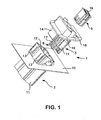
- Fig. 1 shows, in a diagrammatic exploded illustration, a plug connector 1 which is substantially formed by a first and a second plug element which are preferably constructed as a first and a second housing 2, 3.
- a module representing a second contact holder 5, is movably guided in the second housing 3.
- the first housing 2 is pushed through an opening in a support structure 10.
- the first housing 2 is secured to the support structure 10, which in the illustrated embodiment takes the form of a sheet-metal part of a motor vehicle body, such as a pillar of a motor vehicle, by attachment members 13.
- the first housing 2 has a first housing wall 11 that is constructed to be substantially rectangular in cross-section and that defines a second housing receiving opening 12.
- the second housing receiving opening 12 is dimensioned in cross-section such that the second housing 3 may be pushed into the second housing receiving opening 12, in which case the second housing 3 is guided by the first housing wall 11 in a direction of pushing.
- the attachment members 13 are a plurality of latching hooks by means of which the first housing 2 is secured to the support structure 10.
- the second housing 3 also has a substantially rectangular cross-section which is defined by a second housing wall 14.
- the cross-section of the second housing wall 14 is matched to the second housing receiving opening 12 in the first housing 2 such that the second housing 3 may be pushed at least partly into the first housing 2 in a predetermined direction of pushing.
- Opposing sides of the first housing 2 have holding member engaging recesses 15 on opposing faces of the short sides.
- the holding member engaging recesses 15 serve to hold the second housing 3 in a contact position in the first housing 1.
- the second housing 3 has holding members 16 corresponding to the holding member engaging recesses 15 on opposing sides thereof. The holding members 16 engage the holding member engaging recesses 15 in the first housing 2 when the second housing 3 is in the pushed-in condition.
- the second housing wall 14 has a step 26 in a direction of pushing on a side 27 thereof for pushing in.
- a first region 17 of the second housing wall 14 is constructed to be longer in the direction of pushing in.
- the second contact holder 5 is arranged in the first region 17 and is held movably in the second housing 3 in the direction of pushing.
- the first region 17 is for this purpose constructed in the form of a receiving member 8 in which the second contact holder 5 is guided in the direction of pushing.
- Constructed peripherally around the second housing wall 14 is a peripheral seal 18 which bears in sealing manner against the second housing 3.
- the second contact holder 5 is constructed to be substantially cubical and is pushed into the second housing 3 as an insert part.
- the second contact holder 5 has contact openings 19 which receive second electrical contacts 7. Only a few of the second electrical contacts 7 are illustrated for simplicity and are shown in Figs. 9 and 10.
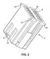
- Fig. 2 shows, in a detailed view, the second contact holder 5.
- the contact openings 19 are made and are constructed in the form of passageways that pass all the way through the second contact holder 5.
- the second electrical contacts 7 are pushed into the contact openings 19 and are held in the contact openings 19.
- the second contact holder 5 has on opposing side faces a respective latching hook 20 which is preferably constructed in one piece with a wall of the second contact holder 5.
- the latching hook 20 has, in an end region which is at a front of the second contact holder 5 in relation to the direction of pushing, a latching projection 21 which extends outwards.
- the second contact holder 5 has, on an opposite end to the latching hook 20, outwardly projecting collars 22 at least in a partial region.
- the collars 22 are constructed in each of four corner regions of the second contact holder 5, which is constructed to be rectangular in cross-section.
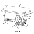
- Fig. 3 shows, in a further perspective illustration, the second housing 3, with the second contact holder 5 pushed into it.
- the second contact holder 5 is in a first position, in which a front side of the second contact holder 5 is arranged virtually flush with a lower edge of the first region 17 of the second housing wall 14.
- the first position is fixed by the latching hook 20 which is used to secure the second contact holder 5 detachably to the second housing 3.
- the latching hook 20 engages a first latching hook receiving recess 23 which is constructed on the second housing wall 14.
- the first latching hook receiving recess 23 is made in the second housing wall 14, open in the direction of pushing.
- a second latching hook receiving recess 24 is made in the second housing wall 14.
- the first and second latching hook receiving recesses 23, 24 are arranged in spring tabs 38, of flexibly resilient construction, on the second housing wall 14.
- the spring tabs 38 consist of two parallel webs which are separated from the second housing wall 14 by way of two parallel longitudinal slots 25.
- the opposite sides, not visible, of the second housing wall 14 and the second contact holder 5 are constructed in a symmetrical manner in relation to the visible sides of the second housing wall 14 and the second contact holder 5.
- the first region 17 of the second housing wall 14 is inwardly offset in a lateral direction and the step 26 provided on the face 27 of the second housing 3.
- a second region 28 set back in opposition to the direction of pushing, having a first contact holder 4 which is fixedly connected to the second housing 3.
- the first contact holder 4 also has contact openings 19 passing all the way through, into which first electrical contacts 6 are pushed and are held. Only a few of the first electrical contacts 6 are illustrated for simplicity and are shown in Figs. 9 and 10.
- the second region 28 is set back with respect to the first region 17 by a step.
- Fig. 4 shows a view into the second housing receiving opening 12 of the first housing 2.
- Two contact zones 30, 31 are constructed next to one another in a contact base 29 of the first housing 2.
- the contact zones 30, 31 are surrounded by the first housing wall 11.
- contact openings 37 of varying construction, in which the first electrical contacts (not illustrated in Fig. 4) are arranged and held.
- the first contact zone 30 is associated with the second contact holder 5.
- Two release members 32 are arranged next to one another on each of two opposing sides of the first contact zone 30 and are directed upwards.
- the four release members 32 are arranged to be symmetrical and each release member 32 has a beveled outer surface 33 which is beveled in the manner of a wedge.
- the second housing receiving opening 12 has inward and outward curves which are matched to the external contour of the second housing wall 14 such that the second housing 3 can only be pushed into the first housing 2 in a fixed orientation, so that the second contact holder 5 is associated with the first contact zone 30.
- the first contact zone 30 and the second contact zone 31 are arranged at the same level.
- Latching hook receiving openings 34 are made in opposing sides of the first contact zone 30. The latching hook receiving openings 34 receive the latching hooks 20 and the spring tabs 38 of the second housing 3.
- Fig. 5 shows a partial detailed cross-section through the plug connector 1, in which the second housing 3 has been pushed into the first housing 2 as far as the release members 32.
- the cross-section illustrated runs on one side through the latching hook 20 and on the opposite side, somewhat offset laterally, through the spring tabs 38 which adjoin the opposing latching hook 20. This clearly shows that the release members 32 bear against both the latching hooks 20 and the spring tabs 38.
- the second contact holder 5 is in the first position, in which the latching hooks 20 are latched into the first latching hook receiving recess 23. In this position, the first and second electrical contacts 6 and 7 of the first and second housings 2 and 3 respectively have already been pushed into one another to a fixed depth in a region of the second contact holder 5.
- the second electrical contacts 7 of the second contact holder 5 have already been pushed fully into the associated first electrical contacts 6 of the first housing 2.
- the pushing force required to push the second electrical contacts 7 of the second contact holder 5 in, in order to make electrical contact with the associated first electrical contacts 6 of the first housing 2 has already been applied.
- the second electrical contacts 7 of the first contact holder 4 of the second housing 3 are not yet in mechanical contact with the associated first electrical contacts 6 of the first housing 2.
- the beveled outer surface 33 of the release members 32 bear against a beveled edge 35 of the latching projections 21, which are arranged on an outer side. If the second housing 3 is now pushed further into the first housing 2, the release members 32 press the spring tabs 38 outward, with the result that the spring tabs 38 having the first latching hook receiving recesses 23 release the latching projections 21 and the second contact holder 5 bears against the contact base 9 of the first housing 2. In this situation, if the second housing 3 is pushed further in, the second housing 3 is pushed deeper into the first housing 2 in a relative movement with respect to the second contact holder 5 and the first housing 2, with the second contact holder 5 performing no further movement in relation to the first housing 2.
- Fig. 6 shows the same section as that in Fig. 5, but with the second housing 3 pushed deeper into the first housing 2.
- the second contact holder 5 bears against an abutment member of the second latching hook receiving recess 24 by means of the latching projections 21, and the second contact holder 5 is seated on the contact base 29.
- the second housing 3 is pushed into the end position in the first housing 2.
- the second electrical contacts 7 of the first contact holder 4 are also already in electrically conductive contact with the associated first electrical contacts 6 of the first housing 2.
- the second housing 3 is pushed deeper into the first housing 2, and now the second electrical contacts 7 of the first contact holder 4 are pushed together with the associated first electrical contacts 6 of the first housing 2.
- Providing the second position for the second contact holder 5 in the form of the second latching hook receiving recess 24 ensures that the second electrical contacts 7 of the second contact holder 5 are pushed reliably and fully into the associated first electrical contacts 6 of the first housing 2.
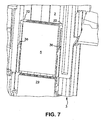
- Fig. 7 shows a further partial detailed cross-section through the plug connector 1, in which the first and the second housings 2, 3 are in the contact position and the second electrical contacts 7 of both the first and the second contact holders 4, 5 are pushed into the first electrical contacts 6 of the first housing 2.
- the second contact holder 5 is seated on the contact base 29.
- the second housing 3 has an abutment member 36 on an inside of the receiving member 8 in which the second contact holder 5 is mounted such that it is axially movable.
- the abutment member 36 is associated with the collar 22 in the direction of movement. In the position illustrated, the collar 22 is arranged at a predetermined spacing above the abutment member 36.
- the second housing 3 is moved out of the first housing 2 and out of the contact position as illustrated in Fig. 7, then the relative positions of the second electrical contacts 7 of the second contact holder 5 and the associated first electrical contacts 6 of the first housing 2 do not change, since because of the contact friction the second contact holder 5 does not change its position but, rather, performs a relative movement with respect to the second housing 3.
- the second electrical contacts 7 of the first contact holder 4 of the second housing 3 are immediately pulled away from the associated first electrical contacts 6 of the first housing 2. Once the second electrical contacts 7 of the first contact holder 4.have been pulled completely away from the associated first electrical contacts 6 of the first housing 2, the second contact holder 5 comes into abutment against the abutment member 36 by means of the collar 22, as illustrated in Fig. 8.
- the abutment member 36 has the effect of pulling the second contact holder 5 along with it, and hence the second contacts of the second contact holder 5 are pulled away from the associated first electrical contacts 6 of the first housing 2.
- the tensile force required for pulling away is also reduced by the fact that the second contact holder 5 is held displaceably in the second housing 3.
- the first and second housings 2, 3 and the first and second contact holders 4, 5 are each made from an insulating material, preferably a synthetic material, which is suitable for an injection molding process.
- Fig. 9 shows that situation of pushing in which occurs, during the procedure of pushing together the first and second housings 2, 3 of the plug connector 1, before Fig. 5, and in which the second electrical contacts 7 of the second contact holder 5 have just made contact with the associated first electrical contacts 6 of the first contact zone 30 of the first housing 2.
- first electrical contacts 6 has been illustrated in the first contact zone 30 and only one of the second electrical contacts 7, indicated by a dashed line, has been illustrated in the second contact holder 5, whereas a plurality of the first and second electrical contacts 6, 7 are arranged in the second contact holder 5 and in the first contact zone 30.
- the second electrical contacts 7 are for example constructed as contact clips or contact sockets.
- the first electrical contacts 6 are for example constructed as contact pins.
- the second electrical contacts 7 of the first contact holder 4 which are arranged in the second region 28 are further away from the associated first electrical contacts 6 of the second contact zone 31 of the first housing 2.
- only one of the first electrical contacts 6 is illustrated in the second contact zone 31 and one of the second electrical contacts 7 is illustrated in the first contact holder 4, although a plurality of the first and second electrical contacts 6, 7 are provided.
- the first electrical contacts 6 of the first contact zone 30 make contact before the first electrical contacts 6 of the second contact zone 31 with the second electrical contacts 7 of the second and first contact holders 5, 4, respectively.
- Fig. 10 shows the arrangement of Fig. 9 but with the second housing 3 pushed even deeper into the first housing 2 and at this point the first electrical contacts 6 of the second contact zone 31 having just been pushed into the second electrical contacts 7 of the first contact holder 4. In this position, the second electrical contacts 7 of the second contact holder 5 have already been pushed into the first electrical contacts 6 of the first contact zone 30, and the second contact holder 5 is seated on the contact base 29.
Landscapes
- Details Of Connecting Devices For Male And Female Coupling (AREA)
Claims (12)
- Elektrischer Steckverbinder, der über zwei komplementäre erste und zweite Steckelemente (2, 3) verfügt, wobei das erste uns das zweite Steckelement (2, 3) über jeweils erste und zweite elektrische Kontakte (6, 7) verfügen und das zweite Steckelement (3) modular aufgebaut ist und über mindestens ein Modul (5) verfügt, das beweglich befestigt ist, wobei sich die zweiten elektrischen Kontakte (7) in dem Modul (5) und in dem zweiten Steckelement (3) befinden, wobei das Modul (5) in dem zweiten Steckelement (3) befestigt ist und so ausgerichtet ist, dass beim Zusammenschieben der beiden Steckelemente (2, 3) zuerst die zweiten elektrischen Kontakte (7) des Moduls (5) mit den zugehörigen ersten elektrischen Kontakten (6) des ersten Steckelements (2) zusammengeschoben werden können, beim weiter Zusammenschieben der beiden Steckelemente (2, 3) wird das Modul (5) in dem zweiten Steckelement (3) verschiebbar befestigt, und die zweiten elektrischen Kontakte (7) des zweiten Steckelements (3) können anschließend in die zugehörigen ersten elektrischen Kontakte (6) des ersten Steckelements (2) geschoben werden, dadurch gekennzeichnet, dass ein Arretierhaken (20) und eine den Arretierhaken aufnehmende Aussparung (23) als Arretiermittel für das Modul (5) bereitgestellt werden, dass der Arretierhaken (20) auf dem Modul (5) ausgebildet ist, und dass die den Arretierhaken aufnehmende Aussparung (23) in einer Wand des zweiten Steckelements (3) hergestellt ist.
- Elektrischer Steckverbinder nach Anspruch 1, dadurch gekennzeichnet, dass die Steckelemente (2, 3) als ein erstes und ein zweites Gehäuse (2, 3) ausgebildet sind, dass ein Kontaktsockel (29) in dem ersten Gehäuse (2) bereitgestellt wird, in dem sich die ersten elektrischen Kontakte (6) befinden, dass das erste und zweite Gehäuse (2, 3) über Führungselemente verfügen, die es ermöglichen, die beiden Gehäuse (2, 3) zusammenzuschieben, im ineinandergeschobenen Zustand der beiden Gehäuse (2, 3) die ersten und die zweiten elektrischen Kontakte (6, 7) einen elektrisch leitenden Kontakt miteinander herstellen, dass das zweite Gehäuse (3) über einen ersten Kontakthalter (4) verfügt und das Modul als den zweiten Kontakthalter (5), in dem sich die zweiten elektrischen Kontakte (7) befinden, dass der erste Kontakthalter (4) mit dem zweiten Gehäuse (3) verbunden ist, dass der zweite Kontakthalter (5) mittels abnehmbarer Arretiermittel (20, 23) in einer Raststellung gehalten wird, dass sich in der Raststellung der zweite Kontakthalter (5) in Schieberichtung vor dem ersten Kontakthalter (4) befindet, dass das erste Gehäuse (2) über ein Ausklinkelement (32) verfügt, das bei einer festen Einschiebtiefe des zweiten Gehäuses (3) in das erste Gehäuse (2), bei der die zweiten elektrischen Kontakte des zweiten Kontakthalters (5) mit den zugehörigen ersten elektrischen Kontakten des ersten Gehäuses (1) elektrisch verbunden werden, die Arretiermittel (20, 23) löst, dass Führungselemente bereitgestellt werden, die den zweiten Kontakthalter (5) nach Lösen der Arretiermittel (20, 23) im Wesentlichen parallel zur Schieberichtung führen, dass nach Lösen der Arretiermittel (20, 23) das zweite Gehäuse (3) tiefer bis zu einer Endlage in das erste Gehäuse (2) hineingeschoben werden kann, wobei das zweite Gehäuse (3) eine relative Bewegung im Bezug auf den zweiten Kontakthalter (5) ausführt und wobei die zweiten elektrischen Kontakte (7) des ersten Kontakthalters (4) des zweiten Gehäuses (3) mit den zugehörigen ersten elektrischen Kontakten des ersten Gehäuses (2) in elektrischen Kontakt gebracht werden.
- Steckverbinder nach einem der Ansprüche 1 oder 2, dadurch gekennzeichnet, dass ein Auflageelement (24) auf dem zweiten Steckelement (3) angebracht ist, durch das die Kapazität des Moduls (5) für eine Verschiebung entgegengesetzt der Einschieberichtung auf eine maximale Tiefe beschränkt ist.
- Steckverbinder nach Anspruch 3, dadurch gekennzeichnet, dass das Auflageelement in Form einer zweiten den Arretierhaken aufnehmenden Aussparung (24) ausgebildet ist, dass sich die zweite den Arretierhaken aufnehmende Aussparung (24) entgegengesetzt zur Einschieberichtung über der ersten den Arretierhaken aufnehmenden Aussparung (23) befindet und für das Einhaken des Arretierhakens (20) bereitgestellt wird.
- Steckverbinder nach einem der Ansprüche 1 bis 4, dadurch gekennzeichnet, dass die erste den Arretierhaken aufnehmende Aussparung (23) in einer Federnase (38) hergestellt ist, die als Teil der Wand des zweiten Gehäuses (3) ausgebildet ist.
- Steckverbinder nach einem der Ansprüche 1 bis 5, dadurch gekennzeichnet, dass der Arretierhaken (20) als Teil der Wand des Moduls (5) ausgebildet ist.
- Steckverbinder nach einem der Ansprüche 1 bis 6, dadurch gekennzeichnet, dass ein zweites Auflagemittel (22, 36) bereitgestellt wird, und dass beim Lösen des zweiten Steckelements (3) von dem ersten Steckelement (2) die zweiten elektrischen Kontakte (7) des Moduls (5) von den zugehörigen ersten elektrischen Kontakten (6) des ersten Steckelements (2) in einer festen relativen Bewegung zwischen dem zweiten Steckelement (3) und dem Modul (5) weggezogen werden, bis die relative Bewegung durch das zweite Auflagemittel (22, 36) gestoppt wird und dann das Modul (5) zusammen mit dem zweiten Steckelement (3) verschoben wird.
- Steckverbinder nach Anspruch 7, dadurch gekennzeichnet, dass das zweite Auflageelement in Form eines Rings (22) und eines Auflageelements (36) ausgebildet ist, dass der Ring (22) auf dem Modul (5) ausgebildet ist und das Auflageelement (36) auf dem zweiten Steckelement (3) ausgebildet ist und diese miteinander in Verbindung stehen.
- Steckverbinder nach einem der Ansprüche 1 bis 8, dadurch gekennzeichnet, dass das Lösemittel in Form eines Ausklinkelements (32) ausgebildet ist, das mit dem Kontaktsockel (29) des ersten Steckelements (2) ein Teil bildet.
- Steckverbinder nach den Ansprüchen 1 und 9, dadurch gekennzeichnet, dass das Lösemittel als ein Ausklinkelement bereitgestellt wird, dass sich das Ausklinkelement (32) teilweise unter dem Arretierhaken (20) befindet und teilweise unter der Wand des zweiten Steckelements (3), das an den Arretierhaken (20) angrenzt, und dass es bei Lösen des Arretiermittels sowohl auf den Arretierhaken (20) als auch auf die Wand wirkt und die Wand im Verhältnis zum Arretierhaken verschiebt.
- Steckverbinder nach einem der Ansprüche 1 bis 10, dadurch gekennzeichnet, dass das zweite Steckelement (3) über eine Wand verfügt, die in einem Einführungsbereich in Schieberichtung des zweiten Steckelements (3) abgestuft ist und wodurch das zweite Steckelement (3) mit dem ersten Steckelement (2) zusammengeschoben werden kann, und dass die Wand weiter unten im Bereich des Moduls (5) herausgeführt wird.
- Zweites elektrisches Steckelement (3) für einen elektrischen Steckverbinder, der über zwei komplementäre Steckelemente (2, 3) verfügt, wobei das zweite Steckelement (3) über zweite elektrische Kontakte (7) verfügt, das zweite Steckelement (3) modular aufgebaut ist und über mindestens ein Modul (5) verfügt, das beweglich befestigt ist, wobei sich die zweiten elektrischen Kontakte (7) in dem Modul (5) und in dem zweiten Steckelement (3) befinden, wobei das Modul (5) in dem zweiten Steckelement (3) befestigt ist und so ausgerichtet ist, dass beim Zusammenschieben der beiden Steckelemente (2, 3) zuerst die zweiten elektrischen Kontakte (7) des Moduls (5) mit den zugehörigen ersten elektrischen Kontakten (6) des ersten Steckelements (2) zusammengeschoben werden können, beim weiter Zusammenschieben der beiden Steckelemente (2, 3) wird das Modul (5) in dem zweiten Steckelement (3) verschiebbar befestigt und die zweiten elektrischen Kontakte (7) des zweiten Steckelements (3) können anschließend in die zugehörigen ersten elektrischen Kontakte (6) des ersten Steckelements (2) geschoben werden, dadurch gekennzeichnet, dass ein Arretierhaken (20) und eine den Arretierhaken aufnehmende Aussparung (23) als Arretiermittel für das Modul (5) bereitgestellt werden, dass der Arretierhaken (20) auf dem Modul (5) ausgebildet ist und dass die den Arretierhaken aufnehmende Aussparung (23) in einer Wand des zweiten Steckelements (3) hergestellt ist.
Priority Applications (1)
| Application Number | Priority Date | Filing Date | Title |
|---|---|---|---|
| EP05002729A EP1569305B1 (de) | 2004-02-24 | 2005-02-09 | Elektrischer Steckverbinder |
Applications Claiming Priority (3)
| Application Number | Priority Date | Filing Date | Title |
|---|---|---|---|
| EP04004159 | 2004-02-24 | ||
| EP04004159 | 2004-02-24 | ||
| EP05002729A EP1569305B1 (de) | 2004-02-24 | 2005-02-09 | Elektrischer Steckverbinder |
Publications (2)
| Publication Number | Publication Date |
|---|---|
| EP1569305A1 EP1569305A1 (de) | 2005-08-31 |
| EP1569305B1 true EP1569305B1 (de) | 2007-04-11 |
Family
ID=34751686
Family Applications (1)
| Application Number | Title | Priority Date | Filing Date |
|---|---|---|---|
| EP05002729A Expired - Lifetime EP1569305B1 (de) | 2004-02-24 | 2005-02-09 | Elektrischer Steckverbinder |
Country Status (1)
| Country | Link |
|---|---|
| EP (1) | EP1569305B1 (de) |
Families Citing this family (1)
| Publication number | Priority date | Publication date | Assignee | Title |
|---|---|---|---|---|
| CN112838436B (zh) * | 2021-01-07 | 2022-05-31 | 苏州浪潮智能科技有限公司 | 一种风扇连接器免工具安装结构 |
Family Cites Families (4)
| Publication number | Priority date | Publication date | Assignee | Title |
|---|---|---|---|---|
| JP2671729B2 (ja) * | 1992-09-29 | 1997-10-29 | 住友電装株式会社 | コネクタ装置 |
| JP2688047B2 (ja) * | 1993-01-13 | 1997-12-08 | 矢崎総業株式会社 | 低挿入力コネクタ |
| JP3145271B2 (ja) * | 1995-05-16 | 2001-03-12 | 矢崎総業株式会社 | 低挿入力コネクタ |
| US5913703A (en) * | 1996-04-24 | 1999-06-22 | Sumitomo Wiring Systems, Ltd. | Connector assembly with sequentially engageable housings |
-
2005
- 2005-02-09 EP EP05002729A patent/EP1569305B1/de not_active Expired - Lifetime
Non-Patent Citations (1)
| Title |
|---|
| None * |
Also Published As
| Publication number | Publication date |
|---|---|
| EP1569305A1 (de) | 2005-08-31 |
Similar Documents
| Publication | Publication Date | Title |
|---|---|---|
| US4975082A (en) | Double engagement structure for terminal and connector | |
| KR101532300B1 (ko) | 커넥터 및 커넥터의 제조 방법 | |
| JP4963702B2 (ja) | 端子位置保証装置を有するコネクタ組立体 | |
| EP1986288B1 (de) | Kurzschlussklemme, Steckverbinder und Montageverfahren dafür | |
| JPS63168976A (ja) | 電気コネクタ | |
| US6926545B2 (en) | Electrical connection box with a lower cover for holding and mounting a connector | |
| US5803756A (en) | Electrical connector with short circuit terminal | |
| US7108566B2 (en) | Electrical plug connector | |
| WO2013178773A1 (en) | Electrical connector | |
| GB2260658A (en) | Electrical connector with module holder | |
| US5454740A (en) | Connector with terminal locking spacer | |
| US20100136853A1 (en) | Connector | |
| EP0390449B1 (de) | Elektrischer Verbinder | |
| JP2005302715A (ja) | 電気プラグ・ソケットコネクタ | |
| US5683257A (en) | Retainer for holding terminals in a unit structure and method of use thereof | |
| JP2900210B2 (ja) | 圧接ターミナル | |
| EP1569305B1 (de) | Elektrischer Steckverbinder | |
| EP3273544B1 (de) | Verbinder | |
| EP1220360B1 (de) | Leiterplattenrandverbinder | |
| WO2021079590A1 (ja) | コネクタ | |
| US20230198191A1 (en) | Connector | |
| JP6730975B2 (ja) | 電気コネクタ及び該電気コネクタ内の接続端子の係止方法 | |
| US20240356262A1 (en) | Joint connector | |
| EP1443606B1 (de) | Verbinder | |
| CN211320403U (zh) | 一种带弹片接触的连接器 |
Legal Events
| Date | Code | Title | Description |
|---|---|---|---|
| PUAI | Public reference made under article 153(3) epc to a published international application that has entered the european phase |
Free format text: ORIGINAL CODE: 0009012 |
|
| AK | Designated contracting states |
Kind code of ref document: A1 Designated state(s): AT BE BG CH CY CZ DE DK EE ES FI FR GB GR HU IE IS IT LI LT LU MC NL PL PT RO SE SI SK TR |
|
| AX | Request for extension of the european patent |
Extension state: AL BA HR LV MK YU |
|
| 17P | Request for examination filed |
Effective date: 20050901 |
|
| AKX | Designation fees paid |
Designated state(s): AT BE BG CH CY CZ DE DK EE ES FI FR GB GR HU IE IS IT LI LT LU MC NL PL PT RO SE SI SK TR |
|
| GRAP | Despatch of communication of intention to grant a patent |
Free format text: ORIGINAL CODE: EPIDOSNIGR1 |
|
| GRAS | Grant fee paid |
Free format text: ORIGINAL CODE: EPIDOSNIGR3 |
|
| GRAA | (expected) grant |
Free format text: ORIGINAL CODE: 0009210 |
|
| AK | Designated contracting states |
Kind code of ref document: B1 Designated state(s): AT BE BG CH CY CZ DE DK EE ES FI FR GB GR HU IE IS IT LI LT LU MC NL PL PT RO SE SI SK TR |
|
| PG25 | Lapsed in a contracting state [announced via postgrant information from national office to epo] |
Ref country code: FI Free format text: LAPSE BECAUSE OF FAILURE TO SUBMIT A TRANSLATION OF THE DESCRIPTION OR TO PAY THE FEE WITHIN THE PRESCRIBED TIME-LIMIT Effective date: 20070411 Ref country code: CH Free format text: LAPSE BECAUSE OF FAILURE TO SUBMIT A TRANSLATION OF THE DESCRIPTION OR TO PAY THE FEE WITHIN THE PRESCRIBED TIME-LIMIT Effective date: 20070411 Ref country code: LI Free format text: LAPSE BECAUSE OF FAILURE TO SUBMIT A TRANSLATION OF THE DESCRIPTION OR TO PAY THE FEE WITHIN THE PRESCRIBED TIME-LIMIT Effective date: 20070411 Ref country code: SI Free format text: LAPSE BECAUSE OF FAILURE TO SUBMIT A TRANSLATION OF THE DESCRIPTION OR TO PAY THE FEE WITHIN THE PRESCRIBED TIME-LIMIT Effective date: 20070411 |
|
| REG | Reference to a national code |
Ref country code: GB Ref legal event code: FG4D |
|
| REG | Reference to a national code |
Ref country code: CH Ref legal event code: EP |
|
| REG | Reference to a national code |
Ref country code: IE Ref legal event code: FG4D |
|
| REF | Corresponds to: |
Ref document number: 602005000836 Country of ref document: DE Date of ref document: 20070524 Kind code of ref document: P |
|
| REG | Reference to a national code |
Ref country code: SE Ref legal event code: TRGR |
|
| PG25 | Lapsed in a contracting state [announced via postgrant information from national office to epo] |
Ref country code: ES Free format text: LAPSE BECAUSE OF FAILURE TO SUBMIT A TRANSLATION OF THE DESCRIPTION OR TO PAY THE FEE WITHIN THE PRESCRIBED TIME-LIMIT Effective date: 20070722 |
|
| PG25 | Lapsed in a contracting state [announced via postgrant information from national office to epo] |
Ref country code: IS Free format text: LAPSE BECAUSE OF FAILURE TO SUBMIT A TRANSLATION OF THE DESCRIPTION OR TO PAY THE FEE WITHIN THE PRESCRIBED TIME-LIMIT Effective date: 20070811 |
|
| PG25 | Lapsed in a contracting state [announced via postgrant information from national office to epo] |
Ref country code: PT Free format text: LAPSE BECAUSE OF FAILURE TO SUBMIT A TRANSLATION OF THE DESCRIPTION OR TO PAY THE FEE WITHIN THE PRESCRIBED TIME-LIMIT Effective date: 20070911 |
|
| NLV1 | Nl: lapsed or annulled due to failure to fulfill the requirements of art. 29p and 29m of the patents act | ||
| ET | Fr: translation filed | ||
| REG | Reference to a national code |
Ref country code: CH Ref legal event code: PL |
|
| PG25 | Lapsed in a contracting state [announced via postgrant information from national office to epo] |
Ref country code: PL Free format text: LAPSE BECAUSE OF FAILURE TO SUBMIT A TRANSLATION OF THE DESCRIPTION OR TO PAY THE FEE WITHIN THE PRESCRIBED TIME-LIMIT Effective date: 20070411 Ref country code: AT Free format text: LAPSE BECAUSE OF FAILURE TO SUBMIT A TRANSLATION OF THE DESCRIPTION OR TO PAY THE FEE WITHIN THE PRESCRIBED TIME-LIMIT Effective date: 20070411 |
|
| PG25 | Lapsed in a contracting state [announced via postgrant information from national office to epo] |
Ref country code: BE Free format text: LAPSE BECAUSE OF FAILURE TO SUBMIT A TRANSLATION OF THE DESCRIPTION OR TO PAY THE FEE WITHIN THE PRESCRIBED TIME-LIMIT Effective date: 20070411 |
|
| PG25 | Lapsed in a contracting state [announced via postgrant information from national office to epo] |
Ref country code: DK Free format text: LAPSE BECAUSE OF FAILURE TO SUBMIT A TRANSLATION OF THE DESCRIPTION OR TO PAY THE FEE WITHIN THE PRESCRIBED TIME-LIMIT Effective date: 20070411 Ref country code: CZ Free format text: LAPSE BECAUSE OF FAILURE TO SUBMIT A TRANSLATION OF THE DESCRIPTION OR TO PAY THE FEE WITHIN THE PRESCRIBED TIME-LIMIT Effective date: 20070411 Ref country code: NL Free format text: LAPSE BECAUSE OF FAILURE TO SUBMIT A TRANSLATION OF THE DESCRIPTION OR TO PAY THE FEE WITHIN THE PRESCRIBED TIME-LIMIT Effective date: 20070411 Ref country code: BG Free format text: LAPSE BECAUSE OF FAILURE TO SUBMIT A TRANSLATION OF THE DESCRIPTION OR TO PAY THE FEE WITHIN THE PRESCRIBED TIME-LIMIT Effective date: 20070711 |
|
| PLBE | No opposition filed within time limit |
Free format text: ORIGINAL CODE: 0009261 |
|
| STAA | Information on the status of an ep patent application or granted ep patent |
Free format text: STATUS: NO OPPOSITION FILED WITHIN TIME LIMIT |
|
| PG25 | Lapsed in a contracting state [announced via postgrant information from national office to epo] |
Ref country code: SK Free format text: LAPSE BECAUSE OF FAILURE TO SUBMIT A TRANSLATION OF THE DESCRIPTION OR TO PAY THE FEE WITHIN THE PRESCRIBED TIME-LIMIT Effective date: 20070411 Ref country code: LT Free format text: LAPSE BECAUSE OF FAILURE TO SUBMIT A TRANSLATION OF THE DESCRIPTION OR TO PAY THE FEE WITHIN THE PRESCRIBED TIME-LIMIT Effective date: 20070411 |
|
| 26N | No opposition filed |
Effective date: 20080114 |
|
| PG25 | Lapsed in a contracting state [announced via postgrant information from national office to epo] |
Ref country code: IT Free format text: LAPSE BECAUSE OF FAILURE TO SUBMIT A TRANSLATION OF THE DESCRIPTION OR TO PAY THE FEE WITHIN THE PRESCRIBED TIME-LIMIT Effective date: 20070411 Ref country code: GR Free format text: LAPSE BECAUSE OF FAILURE TO SUBMIT A TRANSLATION OF THE DESCRIPTION OR TO PAY THE FEE WITHIN THE PRESCRIBED TIME-LIMIT Effective date: 20070712 |
|
| PG25 | Lapsed in a contracting state [announced via postgrant information from national office to epo] |
Ref country code: RO Free format text: LAPSE BECAUSE OF FAILURE TO SUBMIT A TRANSLATION OF THE DESCRIPTION OR TO PAY THE FEE WITHIN THE PRESCRIBED TIME-LIMIT Effective date: 20070411 |
|
| PGFP | Annual fee paid to national office [announced via postgrant information from national office to epo] |
Ref country code: SE Payment date: 20080227 Year of fee payment: 4 |
|
| PGFP | Annual fee paid to national office [announced via postgrant information from national office to epo] |
Ref country code: FR Payment date: 20080218 Year of fee payment: 4 |
|
| PG25 | Lapsed in a contracting state [announced via postgrant information from national office to epo] |
Ref country code: MC Free format text: LAPSE BECAUSE OF NON-PAYMENT OF DUE FEES Effective date: 20080228 |
|
| PG25 | Lapsed in a contracting state [announced via postgrant information from national office to epo] |
Ref country code: IE Free format text: LAPSE BECAUSE OF NON-PAYMENT OF DUE FEES Effective date: 20080211 Ref country code: EE Free format text: LAPSE BECAUSE OF FAILURE TO SUBMIT A TRANSLATION OF THE DESCRIPTION OR TO PAY THE FEE WITHIN THE PRESCRIBED TIME-LIMIT Effective date: 20070411 |
|
| PG25 | Lapsed in a contracting state [announced via postgrant information from national office to epo] |
Ref country code: CY Free format text: LAPSE BECAUSE OF FAILURE TO SUBMIT A TRANSLATION OF THE DESCRIPTION OR TO PAY THE FEE WITHIN THE PRESCRIBED TIME-LIMIT Effective date: 20070411 |
|
| EUG | Se: european patent has lapsed | ||
| GBPC | Gb: european patent ceased through non-payment of renewal fee |
Effective date: 20090209 |
|
| REG | Reference to a national code |
Ref country code: FR Ref legal event code: ST Effective date: 20091030 |
|
| PG25 | Lapsed in a contracting state [announced via postgrant information from national office to epo] |
Ref country code: GB Free format text: LAPSE BECAUSE OF NON-PAYMENT OF DUE FEES Effective date: 20090209 Ref country code: FR Free format text: LAPSE BECAUSE OF NON-PAYMENT OF DUE FEES Effective date: 20090302 |
|
| PG25 | Lapsed in a contracting state [announced via postgrant information from national office to epo] |
Ref country code: HU Free format text: LAPSE BECAUSE OF FAILURE TO SUBMIT A TRANSLATION OF THE DESCRIPTION OR TO PAY THE FEE WITHIN THE PRESCRIBED TIME-LIMIT Effective date: 20071012 Ref country code: LU Free format text: LAPSE BECAUSE OF NON-PAYMENT OF DUE FEES Effective date: 20080209 |
|
| PG25 | Lapsed in a contracting state [announced via postgrant information from national office to epo] |
Ref country code: TR Free format text: LAPSE BECAUSE OF FAILURE TO SUBMIT A TRANSLATION OF THE DESCRIPTION OR TO PAY THE FEE WITHIN THE PRESCRIBED TIME-LIMIT Effective date: 20070411 |
|
| PG25 | Lapsed in a contracting state [announced via postgrant information from national office to epo] |
Ref country code: SE Free format text: LAPSE BECAUSE OF NON-PAYMENT OF DUE FEES Effective date: 20090210 |
|
| PGFP | Annual fee paid to national office [announced via postgrant information from national office to epo] |
Ref country code: DE Payment date: 20130227 Year of fee payment: 9 |
|
| REG | Reference to a national code |
Ref country code: DE Ref legal event code: R119 Ref document number: 602005000836 Country of ref document: DE |
|
| REG | Reference to a national code |
Ref country code: DE Ref legal event code: R119 Ref document number: 602005000836 Country of ref document: DE Effective date: 20140902 |
|
| PG25 | Lapsed in a contracting state [announced via postgrant information from national office to epo] |
Ref country code: DE Free format text: LAPSE BECAUSE OF NON-PAYMENT OF DUE FEES Effective date: 20140902 |